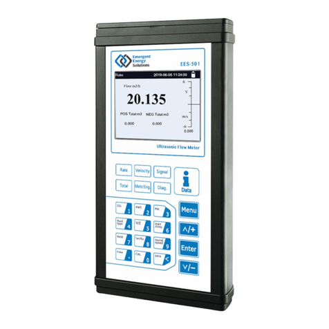
EMERGENT EES-101 User manual

EES-101 SeriesUltrasonicFlowmeter
Version:3.0.0
Ultrasonic Flowmeter Instruction Manual
Model: EES-101
Update
Record
Revision 3.0.1
Date 12 . 2021

EES-101 SeriesUltrasonicFlowmeter
Revision:3.0.1Page2of65
Notice:
Thisinstruction manualisappropriate forEES-101 seriesultrasonic flowmeter.
Thisultrasonic flowmeteradoptsARM.kernelchip and low-voltage wide-pulse sending technology.
Thisinstruction manualcontainsimportantinformation. Pleaseread carefullybeforethe operation ofthe
flowmeter,avoiding damaging flowmeterand improperuse.
Thisinstruction manualwill introduce howtousetheflowmeterstep-by-step, including productcomponent,
installation, wiring, quick setup etc. to make it easierto operate.
Understanding moreaboutthe menu settingscan fulfill yourhigherrequirementswiththe flowmeters powerful
function option and outputfunction.
Warning
Maycause injury.
Attention
Maydamage the flowmeter.
Someofthe instructionsmaybe differenttothe flowmeters you purchased, dependingonconfiguration
requirements,otherwise, thereisno indication aboutthe productdesign and upgrade requirementinthe
instructions, please referto the version number, aswell asthe appendix.

EES-101 SeriesUltrasonicFlowmeter
Revision:3.0.1Page3of65
Product Components
Inspection should be made before installing the Flowmeter. Check to see if the provided parts and components
are in accordance with the packing list. Make sure that there isno damage to the enclosure due to a loose screw
or loose wire, or other damage that mayhave occurred during transportation. Any questions, please contact
Emergent Energy Solutions.

EES-101 SeriesUltrasonicFlowmeter
Revision:3.0.1Page4of65
Content
1Transmitter Installationand Connection.................................................................................6
1.1 Inspectionprior toTransmitter Installation........................................................................................................6
1.2 WireConnecting ................................................................................................................................................7
1.2.1 Power supplyoption ..................................................................................................................................7
1.2.2 Transmitter Wiring ....................................................................................................................................7
1.2.3 LengthenedCable Method.........................................................................................................................7
1.3 Powering on.......................................................................................................................................................9
1.4 KeypadFunctions...............................................................................................................................................9
1.5 KeypadOperation..............................................................................................................................................9
1.6 Flowmeter WindowDescriptions.....................................................................................................................10
2PipeParameter EntryShortcuts.............................................................................................11
2.1 Dual functionkeysmenudescription...............................................................................................................11
2.2 Examples..........................................................................................................................................................12
3MeasurementSite Selection.....................................................................................................14
4Transducer Installation............................................................................................................15
4.1 Installingthetransducers..................................................................................................................................15
4.1.1 Transducer Spacing..................................................................................................................................15
4.1.2 Transducer Mounting Methods................................................................................................................15
4.1.3 VMethod.................................................................................................................................................15
4.1.4 ZMethod .................................................................................................................................................16
4.1.5 NMethod (notcommonlyused)..............................................................................................................16
4.2 Transducer Mounting Inspection......................................................................................................................16
4.2.1 Signal Strength.........................................................................................................................................16
4.2.2 Signal Quality(Qvalue)..........................................................................................................................17
4.2.3 Total TimeandDelta Time......................................................................................................................17
4.2.4 Transit TimeRatio...................................................................................................................................17
4.2.5 Warnings..................................................................................................................................................17
5Operating Instructions.............................................................................................................19
5.1 SystemNormal Identification..........................................................................................................................19
5.2 Zero Set Calibration.........................................................................................................................................19
5.3 Scale Factor......................................................................................................................................................19
5.4 SystemLock.....................................................................................................................................................19
5.5 FrequencyOutput.............................................................................................................................................20
5.6 4~20mACurrentLoop OutputVerification(Optional)...................................................................................20
5.7 Recover theFactoryDefault............................................................................................................................20
5.8 4~20mAAnalogOutputCalibration................................................................................................................21
5.9 ESN..................................................................................................................................................................21
6Windows Display Explanations...............................................................................................22

EES-101 SeriesUltrasonicFlowmeter
Revision:3.0.1Page5of65
6.1 WindowsDisplayCodes..................................................................................................................................22
6.2 DisplayExplanation.........................................................................................................................................23
7ErrorDiagnoses.........................................................................................................................38
7.1 Table1. Error codesandsolutions....................................................................................................................38
7.2 FrequentlyAskedQuestionsandAnswers.......................................................................................................39
8Product Overview.....................................................................................................................40
8.1 Introduction......................................................................................................................................................40
8.2 FeaturesofEES-101 ........................................................................................................................................40
8.3 Specifications...................................................................................................................................................41
9Appendix1-SerialInterface NetworkUseand Communications Protocol..........................42
9.1 Overview..........................................................................................................................................................42
9.2 Direct connectionvia RS-485 tothehostdevice.............................................................................................42
9.3 Communicationprotocolandtheuse...............................................................................................................42
9.3.1 FUJI Protocol...........................................................................................................................................43
9.3.2 MODBUS CommunicationProtocol.......................................................................................................48
10 Appendix1-W211 InsertionTransducer.................................................................................56
10.1 Overview..........................................................................................................................................................56
10.2 MeasurementPointSelection...........................................................................................................................56
10.3 Determining Transducer Spacing &Transducer Installation...........................................................................56
10.4 Transducer Mounting Methods........................................................................................................................58
10.4.1 ZMountingMethod.................................................................................................................................58
10.4.2 PipeParameter EntryShortcuts...............................................................................................................58
11 Appendix 2-WiFiOperationInstructions...............................................................................60
11.1 ABriefIntroductiononFunctions...................................................................................................................60
11.2 Flowmeter DistributionNetworkMode...........................................................................................................60
11.3 Flowmeter connectingnetwork........................................................................................................................61
12 Appendix 6-OperationInstructions ofSDCard....................................................................64
12.1 Technical Specifications..................................................................................................................................64
12.2 OnlineInsertandRemoval ofSD Card............................................................................................................65
12.3 OfflineData Reading:......................................................................................................................................65
Update Information:
__________________________________________________________________________________________
__________________________________________________________________________________________
__________________________________________________________________________________________

EES-101 SeriesUltrasonicFlowmeter
Revision:3.0.1Page6of65
1TransmitterInstallation and Connection
1.1 Inspection prior toTransmitterInstallation
You will find a "Position Drawing" in the
package. Please use it as a template to provide
guidance on product placement as you installthe
flowmeter. Then drill 4 installing holes at the screw
positionsshown on the drawing with the 5.0mm
(0.25") drill.
Attention
When installing please ensure the frontcoverissecure and will notfall open.
86 mm
135 mm
5.32lnch
3.39lnch
Positiondrawing
1.Placethistemplateon thewall anddrill 4
holesof 5mmdiameter&40mmdeep.
2.Insertaplasticbushing intoeachofthe4
holes.
3.Screw4pcsPA4×30mm selftapping
screwsthroughthetransmitter enclosure
baseandattachittothewall.
4.Tightenthescrewsto secureto the
enclosureonthewall.
MODELDCT1188
DigitalCorrelationTransit -TimeFlowmeter
135mm
5.32lnch
86mm
3.39lnch
Take out the enclosed mounting screws and
plastic anchors. Insert the plastic anchors into
the installation holes. Install the flow meter
accordingly.

EES-101 SeriesUltrasonicFlowmeter
Revision:3.0.1Page7of65
1.2 WireConnecting
1.2.1 Power supplyoption
Customersshould pay special attention to the specified power supplyoptions when wiring.
Factorystandard power supplyis10~36VDC/1A max.
To ensure the transmitter can work normally, please payattention to the followings when wiring:
Ensure that power connections are made in accordance with the specifications shown on the transmitter.
1.2.2 Transmitter Wiring
Once the electronics enclosure has been installed, the flowmeter wiring can be connected.
Once you open the case, you will find the transmitter interfaces labelsfrom leftto right as follows:
Power supply, Relayoutput, OCTOutput, Upstream transducer, Downstream transducer, 4-20mA, RS485
interface.
Refer to the below diagram for specific connection:
1.2.3 Lengthened CableMethod
Standard cable length of sensor is9 meters (~30 feet);itcan be lengthened to be 300 metersaccording to the
actual need for fluid measurement. Please contact Emergent Energy for specific applications where longer cables
will be needed.
Red Bushing
Flow
DC+ DC- GE
DC10 -36V EUP+UP- EDN+ DN-
TRANSDUCER I+I-
4-20mA
Blue Bushing
Being testedpipe
Black
Red
Shield
PipeStraps
UpstreamTransducer DownstreamTransducer
OCT+OCT-
OCT OUT
RL+RL-
RELAY
Shield
Red
Black
Up-Stream
Down-Stream
10~36VDC
AB
RS485

EES-101 SeriesUltrasonicFlowmeter
Revision:3.0.1Page8of65
1.2.3.1 SketchoflengthenedCable
1.2.3.2 JunctionBoxRequirements
The flowmeter usesa sealed waterproof junction box to splice together lengthened transducer cables,installing
62press-connections, the recommended minimum specifications of the junction box is115 90 55mm.
1.2.3.3 Cable Specifications
Name: Shielded Twisted Pair
Administer Standard: JB8734.5-1998
Diameter: Φ5 mm
TwistLine Space: 50 mm
Multi Core Line: 0.4 mm2/radix
Wire Guage: AWG20#
Core Line Color:Red and Black
Shield Floor:128 Intwine
Warning
Wire with poweroff. Theflowmetermustbe reliable grounding before installation.

EES-101 SeriesUltrasonicFlowmeter
Revision:3.0.1Page9of65
1.3 Poweringon
Assoon as the flowmeter isswitched ON (powered ON), the self-diagnosisprogram will startto run. Ifany
errorsare detected, an error code will displayon the screen (Refer to -Error Diagnoses if any error appear).
After that self-diagnosis, the systemwillrun automaticallyaccording to the latest stored input parameters.
Ifthe installation isaccomplished when system isswitched on, gain adjustment can be monitored in Window M01
(Access by pressing Menu, 0, 1). Generally, after arriving at this screen, the upper right corner of the
display showstwo steps of *Iand *G, the systemwillactivate the normal measurement condition automatically.
And the upper right corner will show "*R". Ifthe signal isnot ideal, the above processmaycycle several times.
Ifthe meter s being installed for the first time, the customer need to input the new installation parameters. The
systemwill defaultto the laststored settings and automaticallydisplaythemat next power on.
1.4 KeypadFunctions
~ And To inputnumbers.
Backspace ordelete characters to the left.
Selectamenu.Press thiskeyfirst,inputtwo
menu numbers and thenenterthe selected menu. For
example, toinputapipe outside diameter,press
keys,where"11"isthe windowIDto
displaythe parameterforpipe outside diameter.
The keypad shortcuttovisit a specific windowisto pressthe keyatanytime, then inputthe 2-digitwindow
IDcode. Forexample, toinputorcheck the pipe outside diameter,justpress the keysforwindow
IDcode 11.
Anothermethod tovisit aparticularwindowistopress and keystoscroll the screen. Forexample, if
the currentwindowIDcode isM02, press keytoenterWindowM01, press the button againtoenter
WindowM00;then,press the keytoback WindowM01, and pressthe keyagaintoenterWindow
M02.
Windowsareseparated intothree types:(1)DataType,such asM11, M12;(2)Option Type, such asM14;(3)
PureDisplayType, such asM01, M00.
Youcancheckthe correspondingparameters byvisiting theDataType Windows.Ifyou wanttomodifythe
parameters,afterpress ,and thedigits,and thenpress againtoconfirm.
Thiskeypad isdual function keypad:
1. When separatelypressed, isshortcut function,
referring to "2. Quicklyset menu instructions ";
2. Press Menuand Number key, isMenu key,
referring to"6.Menu WindowDescription".
Follow these guidelines when using the Flowmeter
keypad (Refer to Keypad Figure):
0 9 ●
<
^And Return to the lastmenu or to open
the next menu. Actsas "+"and "-"functions when
entering numbers.
1.5 KeypadOperation
The flow meter uses the window software designed access all of the parameters entered, the instrument setup and
measurement parameters are broken down into more than 100 independent operator windows. The operator can
input parameters, modify settings or display measurement results by "visiting" a specific window. These windows
are arranged by 2-digit serial numbers (including "+" sign) from 00~99, then to +0, +1, etc. Each window serial
number, or so-called window ID code, has a defined meaning. For example, Window M11 indicates the
parameter input for pipe outside diameter, while Window M25 indicates the mounting spacing between the
transducers, etc. (Refer – Windows Display Explanations).
^
Menu
Menu
1 1
Menu
Menu 1 1
^
^
^ ^
^^
Enter Enter

EES-101 SeriesUltrasonicFlowmeter
Revision:3.0.1Page10of65
Example1:Toenterapipe outside diameterof219.234, the
procedure isasfollows:
Press keystoenterWindowM11 (the
numericalvalue displayed currentlyisapreviousvalue).Now
press key.The symbol">"and the flashing cursorare
displayed atthe left end ofthe secondline on theScreen.Then
inputthe value parameters
.
You cancheckthe selected option byvisiting Option Type
Windows.Ifyou wanttomodifyit,you mustpress first,
the symbol">"and the flashing cursoraredisplayed atthe left
ofthe Screen. Operatorcanusethe and toscroll
the screen and getthe required value then press to
confirm.
Forexample, if the pipe materialis"StainlessSteel",Press
toenterWindowM14, press tomodify
the options.Selectthe "1. Stainless Steel"option bypressing
and , then press to confirm the selection.
Attention
Generally,press keyfirstifoperatorwantstoenter"modify"status.Ifthe "modify" isstill not
possibleeven afterpressingthe key,itmeansthatsystemislocked byapassword. To
"Unlock"it, select"Unlock"in WindowM47 and enterthe originalpassword.
1.6 FlowmeterWindowDescriptions
These windowsareassigned asfollows:
01~08 FlowTotalizerDisplay:todisplayflowrate, positivetotal,negativetotal,nettotal,velocity,date&
time, presentoperation andflowresultstoday, etc.
10~29InitialParameterSetup:toenterpipe outside diameter,pipe wall thickness,fluidtype, transducertype,
transducermounting method and spacing, etc.
30~38 FlowUnitsOptions:toselectthe flowunit such ascubicmeter,literorotherunits,can turntotalizers
on/off and resettotalizers, etc.
40~49 Setup options:Scaling factor, systemlock (WindowM47), etc.
55~89 Inputand outputsetup:dateand time, ESN,communication baud rate setting, etc.
90~98 Diagnoses:Signalstrengthand signalquality(WindowM90),TOM/TOS*100 (WindowM91),flow
sound velocity(WindowM92),totaltimeand deltatime(WindowM93),Reynoldsnumberand factor
(WindowM94),etc.
+0~+5Appendix:poweron/off time, totalworking hours, on/off timesand a single-accuracyfunction calculator.
Attention
The otherwindowsforhardware adjustmentare reservedbythe manufacturer.
Menu 1 1
Enter
219●234
5Enter
Pipe OuterDiameter
>_
Enter
^
^
Enter
Menu 14Enter
^
^
Enter
Pipe Material[14
>1.StainlessSteel
Enter
Enter

EES-101 SeriesUltrasonicFlowmeter
Revision:3.0.1Page11of65
2PipeParameterEntryShortcuts
2.1 Dualfunction keysmenu description
Press key
DisplayNetFlowToday/FlowMax /FlowMin/The
Average/CurrentRate in turn.
Press key
DisplayDayTotalizerFlow/MonthlyTotalizerFlow
/YearlyTotalizerFlowin turn.
Press key
DisplayTotalizerStart and Stop in turn.
Press key
Displayinstantaneouscoolcapacityand coolcapacity
totalizer.
Press key
Displayinstantaneousheatcapacityand heatcapacity
totalizer.
Press key
Displaythe temp in, outand temperature difference .
Press key
DisplayFlowRate and Velocity.
Press key
DisplayFlowSound Velocity.
Press key
DisplaySignalStrength and SignalQuality.
FlowMax. 6.56m3/h
DayTotalizer
700.00m3/h
Timing1525sec
ON5.858m3
EFR0.0000KW*R
ENT0x1KWh
EFR0.0000KW*R
EPT0x1KWh
In-Out-DeltaC[07
6.218.21-
2.00
Flow20.112m3/h*R
Vel 1.0415m/s
FluidSoundVelocity
0.00m/s
Strength+Quality[90
UP:00.0DN:00.0Q=00

EES-101 SeriesUltrasonicFlowmeter
Revision:3.0.1Page12of65
Press key
Press Enttostart ManualTotalizer,then press Entto
end ManualTotalizer,press EnttoinputStandard
TotalizertogetthefinalKfactor.Completethe
calibration with pressing Entto store.
Press key
Set"Zero Point"and the same asMenu 42.
Press key
DisplaySystemErrorCodes.
2.2 Examples
Forexample, measuring the diameterof219mmand pipe wall thickness of6mm, measuring mediumiswater,
PipeMaterialiscarbon steel,No Liner, can be operated asfollows:
Step1. Pipe outside diameter:
Press the keystoenterWindow
M11, and enterthe pipe outside diameter,and
then press the keyto confirm.
Step2. Pipe wall thickness
Press the keytoenterWindow
M12, and enterthe pipe wall thickness,and
press the keyto confirm.
Step3. Pipe Material
Press the keystoenterWindow
M14, press the key,pressthe or
keytoselectPipeMaterial,andpress the
keyto confirm.
Step4. Transducertype
(The transmitterisavailableforvarious
transducertypes.)
Press the keytoenterM23, and
then press ,nextpress or to
selectflowtransducertype1. CP037, finally
press to confirm.
ManualCalibrate
PressEntWhenReady
SetZero[42
PressENTWhenReady
*R-------------[08
SystemNormal
Menu 1 1
Enter
PipeOuterDiameter
219.00mm
Menu 12
Enter
Pipe WallThickness
6mm
Menu 14
Enter ^
^
Enter
Pipe Material[14
0. Carbon Steel
Menu 2 3
Enter ^
^
Enter
TransducerType [23
1.CP037

EES-101 SeriesUltrasonicFlowmeter
Revision:3.0.1Page13of65
Step5. Transducermounting methods
Press the keytoenterWindow
M24, press the key,pressthe or
keytoselecttransducer-mounting
method, and press the keyto confirm.
Step6. AdjustTransducerspacing
Press the keytoenterWindow
M25, accuratelyinstall the transduceraccording
tothe displayed transducermounting spacing
and the selected mountingmethod (Referto
Installing the Transducers inthischapter).
Step7. Displaymeasurementresult
Press the keystoenterWindow
M01 todisplaymeasurementresult.(Baseon
the actualmeasurement)
Menu 2 4
Enter ^
^
Enter
Transducer Mounting
0. V
Menu 2 5 TransducerSpacing
179.55mm
Menu 0 1Flow0.1129m3/h*R
Vel 1.0415m/s

EES-101 SeriesUltrasonicFlowmeter
Revision:3.0.1Page14of65
3Measurement Site Selection
When selecting a measurement site, itisimportant to select an area where the fluid flow profile isfullydeveloped
(achieved laminar flow) to guarantee a highlyaccurate measurement. Use the following guidelines to select a
proper installation site:
Choose a section of pipe that isalwaysfullof liquid, such as a vertical pipe with flow in the upward direction or a
fullhorizontal pipe.
Ensure enough straight pipe length at leastequal to the figure shown below for the upstream and downstream
transducersinstallation.
Ensure that the pipe surface temperature at the measuring point iswithin the transducer temperature limits.
Consider the inside condition of the pipe carefully. Ifpossible, select a section of pipe where the inside isfree of
excessive corrosion or scaling. This is especially applicable on galvanized rigid piping that might have
significant rust on the inside of the pipe.
10D min
L ≥10D
L ≥5D
10D min
10D min
L ≥50D
L ≥10D
L ≥30D
D
5D min
0.5D min
L≥5D
L≥10D L ≥5D
L≥50D
P
L≥30D L≥10D
StraightlengthofUpstream
piping
Name Straightlengthof Downstream
piping
Pump
Value
Diffuser
Tee
90obend
Reducer
Detector
FlowcontrolleddownstreamFlowcontrolledupstream
CheckValue
CheckValue

EES-101 SeriesUltrasonicFlowmeter
Revision:3.0.1Page15of65
4TransducerInstallation
4.1 Installingthetransducers
Before installing the transducers, clean the pipe surface where the transducers are to be mounted. Remove anyrust,
scale orloose paintand make a smooth surface. Choose asection ofsound conductingpipe forinstalling the
transducers.Applya wide band ofsonic coupling compound down thecenterofthe face ofeach transduceras
well ason the pipe surface, ensure there are no air bubblesbetween the transducers and the pipe wall, and then
attach the transducers to the pipe with the strapsprovided and tighten themsecurely.
Note:
The two transducers shouldbe mounted atthe pipe’scenterline on horizontalpipes.
Make sure thatthe transducermounting direction isparallelwith the flow.
During the installation, thereshould be no air bubblesorparticlesbetween the transducerand the pipe wall. On
horizontalpipes, the transducers should bemounted in the 3 o’clock and 9o’clock positionsofthe pipe section in
orderto avoid anyair bubblesinside the top portion ofthe pipe. (Referto TransducerMounting). Ifthe
transducers cannotbe mounted horizontallysymmetricallydue to limitation ofthe localinstallation conditions, it
maybe necessarytomountthe transducers ata location where there isa guaranteed full pipe condition (the pipe is
alwaysfull ofliquid).
4.1.1 TransducerSpacing
Afterentering the required parameters, the spacing between the ENDSofthe two transducers isconsideredasthe
standard transducerspacing (Referto Top Viewon transducermounting methods). Check the datadisplayed in
WindowM25and space the transducers accordingly.
4.1.2 TransducerMountingMethods
Three transducermounting methodsare available. Theyare respectively:Vmethod, Zmethod and Nmethod. The
Vmethod isprimarilyused on small diameterpipes(DN100~300mm, 4〞~12〞).TheZmethod isused in
applicationswhere the Vmethod cannotwork due topoorsignalorno signaldetected. In addition, the Zmethod
generallyworksbetteron largerdiameterpipes(overDN300mm, 12〞)orcastiron pipes.
The Nmethod isan uncommonlyused method. Itisused on smallerdiameterpipes(belowDN50mm, 2〞).
4.1.3 VMethod
The Vmethod isconsidered asthe standard method. Itusuallygivesa more accurate reading and isused on pipe
diameters ranging from25mmto 400mm(1"~16〞)approximately. Also, it isconvenientto use, butstill
requiresproperinstallation ofthe transducers, contacton the pipe atthe pipe’scenterline and equalspacing on
eitherside ofthe centerline.
DownstreamTransducer
UpstreamTransducer
Flow
TransducerSpace
Flow
SideView TopViewSection
PipeStrap
Transducer

EES-101 SeriesUltrasonicFlowmeter
Revision:3.0.1Page16of65
4.1.4 ZMethod
The signaltransmitted in a Zmethod installation hasless attenuation than a signaltransmitted with the Vmethod
when the pipesaretoo large,there are some suspended solid in the fluid, orthe scalingand linerare too thick .
Thisisbecausethe Zmethod utilizesa directlytransmitted (ratherthan reflected)signalwhich transversesthe
liquid onlyonce.
The Zmethod isable to measure on pipe diameters ranging from100mmto 800mm(4〞~32〞)approximately.
Therefore, we recommend the Zmethod forpipe diametersover300mm(12〞).
4.1.5 NMethod (notcommonlyused)
With the Nmethod, the sound wavestraverse the fluid three timesand bounce twice offthe pipe walls. Itis
suitable forsmallpipe diametermeasurement.
The measurementaccuracycan be improved byextending the transit distance with the Nmethod (uncommonly
used).
4.2 TransducerMounting Inspection
Checkto see if the transducerisinstalled properlyand if there isan accurate and strong enough ultrasonic signal
to ensure properoperation and high reliabilityofthe transducer. Itcan be confirmed by checking the detected
signalstrength, totaltransit time, delta time aswell astransit time ratio.
The "mounting"condition directlyinfluencesthe flowvalue accuracyand systemlong-time running reliability.In
mostinstances, onlyapplya wide band ofsonic coupling compound lengthwise on theface ofthe transducerand
stick it to the outside pipe wall to getgood measurementresults. However, the following inspectionsstill need to
be carried outin orderto ensure the high reliabilityofthemeasurementand long-termoperation ofthe instrument.
4.2.1 SignalStrength
Signalstrength (displayed inWindowM90)indicatesa detected strength ofthe signalboth fromupstreamand
downstreamdirections. The relevantsignalstrength isindicated bynumbers from00.0~99.9. 00.0 representsno
signaldetected while 99.9 representsmaximumsignalstrength.
Normally, the strongerthe signalstrength detected, the longerthe operation ofthe instrumentreliably, aswell as
the more stable the measurementvalue obtained.
Adjustthe transducerto the bestposition and check to ensure thatenough sonic coupling compound isapplied
adequatelyduring installation in orderto obtain themaximumsignalstrength.
DownstreamTransducer
UpstreamTransducer
Flow
TransducerSpacing
Flow
SideView Top ViewSection
PipeStrap
Transducer
DownstreamTransducer
UpstreamTransducer
Flow
TransducerSpacing
Flow
SideView TopViewSection
PipeStrap
Transducer

EES-101 SeriesUltrasonicFlowmeter
Revision:3.0.1Page17of65
Systemnormallyrequiressignalstrength over60.0, whichisdetected fromboth upstreamand downstream
directions. Ifthe signalstrength detected istoo low, the transducerinstallation position and the transducer
mounting spacing should bere-adjusted and the pipe should be re-inspected. Ifnecessary, change the mounting
method to be Zmethod.
4.2.2 SignalQuality(Q value)
Qvalue isshort forSignalQuality(displayed in WindowM90). Itindicatesthe levelofthe signaldetected. Q
value isindicated bynumbersfrom00~99. 00representsthe minimumsignaldetected while 99 representthe
maximum.
Normally, the transducerposition should be adjusted repeatedlyand coupling compound application should be
checkedfrequentlyuntil the signalqualitydetected isasstrong aspossible.
4.2.3 TotalTimeand DeltaTime
"TotalTime and Delta Time", which displaysin WindowM93, indicatesthe conditionofthe installation. The
measurementcalculationsin the Flowmeterare based upon these two parameters. Therefore, when "DeltaTime"
fluctuateswidely, the flowand velocitiesfluctuate accordingly, thismeansthatthe signalqualitydetected istoo
poor. Itmaybe the resulted ofpoorpipe-installation conditions, inadequate transducerinstallation orincorrect
parameterinput.
Generally, "Delta Time"fluctuation should be less than ±20%.Onlywhen the pipe diameteristoo smallor
velocityistoo lowcan the fluctuation be wider.
4.2.4 Transit TimeRatio
Transit Time Ratio indicatesif the transducermounting spacing isaccurate. Thenormaltransit time ratio should
be 100+/-3 if the installation isproper. Check it in WindowM91.
4.2.5 Warnings
(1) Pipeparameters entered mustbe accurate;otherwise the Flowmeterwill notwork properly.
(2) During the installation, applyenough coupling compoundsin orderto stick the transducers onto the
pipe wall. While checking the signalstrength and Qvalue, move the transducers slowlyaround the
mounting site until the strongestsignaland maximumQvalue can be obtained. Make sure thatthe
largerthe pipe diameter, the more the transducers shouldbe moved.
(3) Checkto be sure the mounting spacing isaccordance with the displayin WindowM25 and the
transducerismounted atthe pipe’scenterline on the same diameter.
(4) Payspecialattention to those pipesthatformed bysteelrolls(pipe with seams), since such pipe is
alwaysirregular.Ifthe signalstrength isalwaysdisplayed as0.00, thatmeansthere isno signal
detected. Thus, it isnecessaryto check thatthe parameters (including all the pipe parameters) have
been entered accurately.Check tobe surethe transducermounting method hasbeen selected properly,
the pipe isnotworn-out, andthe linerisnottoo thick. Make sure there isindeed fluid in the pipe or
the transducerisnottoo close to a valve orelbow, and there are nottoo manyair bubblesin the fluid,
etc. With the exception ofthese reasons, if there isstill no signaldetected, the measurementsite has
to be changed.
Attention
Ifthe transittime ratio isover100±3,it isnecessaryto check:
(1) Ifthe parameters (pipe outside diameter, wall thickness, pipe material, liner, etc.)have
been enteredcorrectly,
(2) Ifthe transducermounting spacing isaccordance with the displayin WindowM25,
(3) Ifthe transducerismounted atthe pipe’scenterline on the same diameter,
Ifthe scale istoo thick orthe pipe mounting isdistorted in shape, etc.

EES-101 SeriesUltrasonicFlowmeter
Revision:3.0.1Page18of65
(5) Make sure thatthe Flowmeterisable to run properlywithhigh reliability. The strongerthe signal
strength displayed, the higherthe Qvalue reached. The longerthe Flowmeterrunsaccurately, the
higherthe reliabilityofthe flowratesdisplayed. Ifthere isinterference fromambientelectromagnetic
wavesorthe signaldetected istoo poor, the flowvalue displayed isnotreliable;consequently,the
capabilityforreliable operation isreduced.
(6) Afterthe installation iscomplete, poweron the instrumentand check the result accordingly.

EES-101 SeriesUltrasonicFlowmeter
Revision:3.0.1Page19of65
5Operating Instructions
5.1 SystemNormalIdentification
Press the keys.Ifthe letter"*R"displayson the screen, it indicatessystemnormal.
Ifthe letter"G"isdisplayed,it indicatesthatsystemisadjusting the signalgain priorto the measurement. Also, it
meanssystemnormal. Onlywhen the adjustmenttakestoo long(>2min)withoutstopping can systembe
identified asabnormal.
Letter"I"indicatesno signalisbeing detected. Check thetransducerwiring connectionsare correct, the
transducers are installed firmly, etc.
5.2 Zero SetCalibration
Once zero flowoccurs, a zero pointmayindicate on eachmeasuring instrument, butthe displayed measuring
value isnotequalto "0", thisvalue indicates"Zero". To anymeasuring instrument, thesmallerthe "Zero"is, the
betterthe qualityis. Conversely, if the Zero istoo big, thatindicatesthe qualityofthe instrumentispoor.
Ifthe zero setpointisnotattrue zero flow, a measurementdifference mayoccur. Thesmallerthe physical
measurementcapacityis, thelargerthe measurementdifference fromthe zero pointwill exist. Onlywhen zero
pointreduced toa definite degree, ascompared with the physicalmeasurementcapacity, can the measuring
difference fromzero pointbe ignored.
Foran ultrasonicFlowmeter,the measurementdifference fromzero pointcannotbe ignored atlowflow. Itis
necessaryto performa staticzero setcalibration to improve lowflowmeasurementaccuracy.
Press WindowM42 to setthe Zero, press first, and then wait the readingsdisplayisfinished. Ifthisis
carried outwith flow, the flowwill be displayed as"0",M43 can help to restore settings.
5.3 ScaleFactor
Scale factorrefers to the ratio between "actualvalue"and "reading value".Forexample, when the measurement
and is2.00, and it isindicated as1.98on the instrument, the scale factorreadingis2/1.98. Thismeansthatthe
bestscale factorconstantis1.
However, it isdifficult to keep the scale factoras"1"on the instrumentespeciallyin batch productions.The
difference iscalled "consistency".
During operation, there still existspossible difference inpipe parameters, etc. The "scale factor"maybe necessary
when used on differentpipes. Thus, scale factorcalibration isspeciallydesigned forcalibrating the differences
thatresult fromapplication on differentpipes. The scale factorentered mustbe one thatresultsfromactual
calibration. The scale factorcan be inputin WindowM45.
5.4 SystemLock
Systemlock isreadable butnotmodifiable to preventoperation errordue to unauthorized tampering by
unauthorized personnel.
Press the keys,if displays"Unlock"on the screen, thenpress the key, enter6 numerically
long password, and then pressthe keyto confirm.
Unlockit byusing the selected password only. Press , if "lock"isdisplayed on the screen, then
press the keyand enterthe correctpassword, then press to confirm.
Keep the password in mind orrecorded in a safe place, otherwise the instrumentcannotbe used.
Menu 0 8
Enter
Menu 4 7 Enter
Enter
Menu 4 7
Enter Enter

EES-101 SeriesUltrasonicFlowmeter
Revision:3.0.1Page20of65
5.5 Frequency Output
The Flowmeterisprovided with a frequencyoutputtransmitterfunction. The high orlowfrequencyoutput
displayed indicatesthe high orlowflowrate reading. The usercan resetthe frequency outputaswell asflowrate
ashisrequirements.
Forexample:if a pipe flowrange is0~3000m3/h, the relative frequencyoutputrequired is0~5000Hz, and the
configuration isasfollows:
In WindowM68 (lowlimitfrequencyoutputflowvalue),input0;
In WindowM69 (high limit frequencyoutputflowvalue), input3000;
TypicalOCTOutputwiring diagramasbelow:
OCTOutputWiring Diagram
5.6 4~20mA CurrentLoop OutputVerification(Optional)
Processing a currentloop outputexceeding an accuracyof1%, the flowmeterisprogrammable and configurable
withmultiple outputmodessuch asflowrate orfluid velocity. Selectin WindowM55.Fordetails, please referto
"WindowsDisplayExplanations".
In WindowM56, entera 4mAflowrate orfluid velocityvalue. Enterthe 20mAflowrate orfluid velocityvalue
in WindowM57. Forexample, if the flowrange in a specific pipe is0~1000m3/h, enter0 in WindowM56 and
1000 inWindowM57.
Calibrating and testing the currentloop isperformed in WindowM58. Complete the stepsasfollows:
Press , move or to display"0mA","4mA","8mA", "12mA","16mA", "20mA"
readings, connectan ammeterto testthe currentloop outputand calculate the difference. Calibrate it if the
difference iswithin tolerance. Ifthe difference iswithouttolerance, referto the "Analog OutputCalibration"to
calibrate the currentloop.
Checkthe presentcurrentloop outputinWindowM59 asit changesalongwith change in flow.
5.7 RecovertheFactory Default
Press keysto Windowm37, press or keyto choose"Reset"keysto recoverthe
factorydefault.
OCT+OCT-
OCTOUT
COM
RL1RL2
RELAY EUP+ UP-
TRANS
5~10K1/4w Vcc
Sig
Menu 5 8 Enter ^
^
Menu 37Enter ^
^
Table of contents
Other EMERGENT Measuring Instrument manuals
Popular Measuring Instrument manuals by other brands
Zenner
Zenner MC Assembly instructions
Packet Power
Packet Power BGS72 Installation, operation and maintenance manual
EINHELL
EINHELL NKL 90/4 operating instructions
Boumatic
Boumatic StepMetrix Installation, Operation Maintenance & Service Instructions

NanoSense
NanoSense enocean EP5000E installation manual

Campbell
Campbell cs215 instruction manual
