EMERGENT EES-401 User manual

Revision:3.0.0 Page1of90
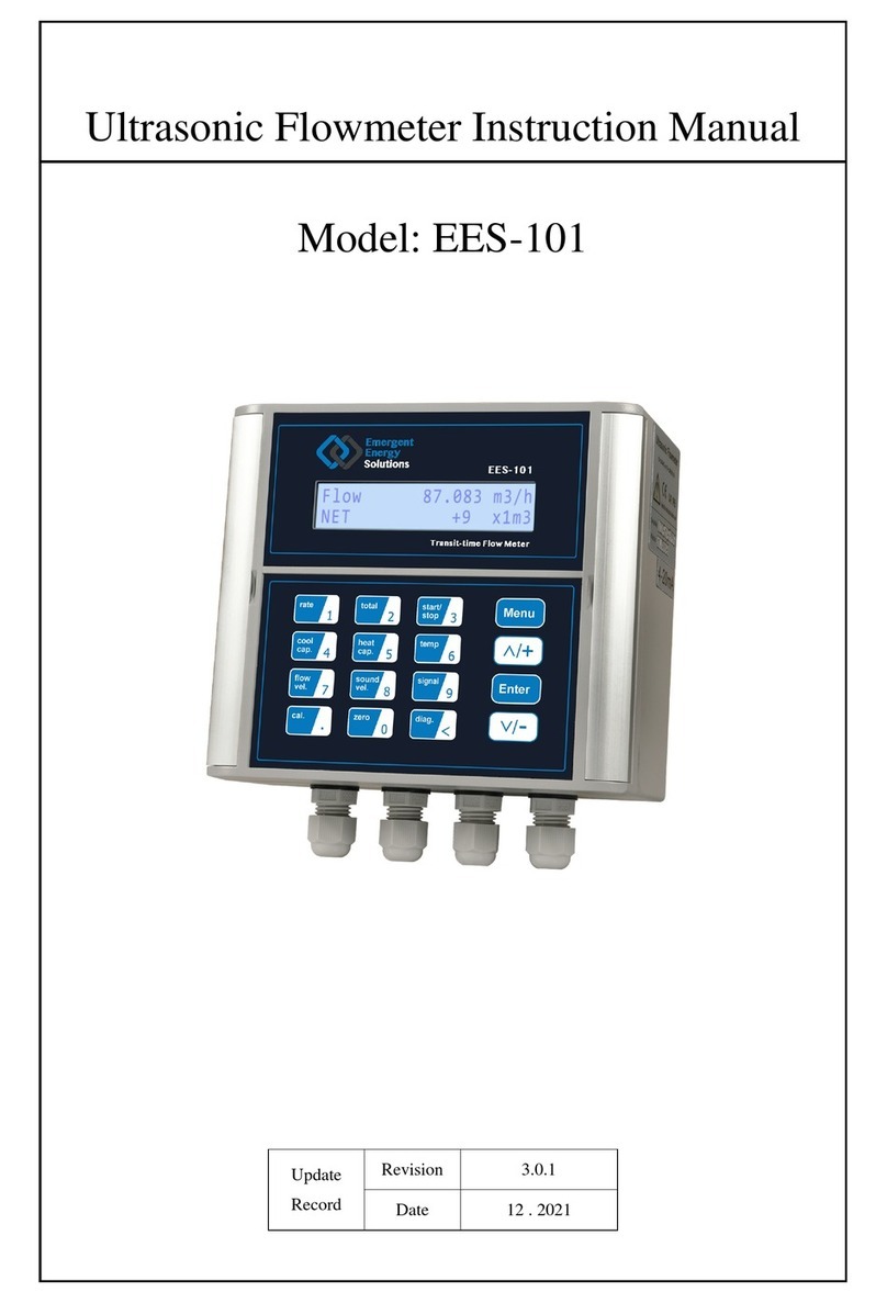
Ultrasonic Energy Meter Instruction Manual
Model: EES-401
Update
Record
Revision 3.0.1
Date 12 . 2021

EES-401 SeriesUltrasonicEnergyMeter
Revision:3.0.1 Page2of90
Notice
Thankyou forchoosing the EES-401 Ultrasonic EnergyMeterwith ARM.FPGAchip and low-voltage wide-pulse
sending technology.
Thisinstruction manualcontainsimportantinformation. Pleaseread carefullybefore the operation ofthe Energy
Meter, avoiding damaging EnergyMeterand improperuse.
Thisinstruction manualwill introduce howto usethe EnergyMeterstep-by-step, including productcomponent,
installation, wiring, quick setup etc. to make it easierto operate.
Understanding more aboutthe menu settingscan fulfill yourhigherrequirementswith the EnergyMeters
powerfulfunction option andoutputfunction.
Warning
Maycause injury.
Attention
Maydamage the EnergyMeters.
Some ofthe instructionsmaybe differentto the EnergyMeters you purchased,depending on configuration
requirements, otherwise, there isno indication aboutthe productdesign and upgrade requirementin the
instructions, subjectto the EnergyMeterdisplay, lease referto the version number, aswell asthe appendix.

EES-401 SeriesUltrasonicEnergyMeter
Revision:3.0.1 Page3of90
Product Components
Inspection should be made before installing the EnergyMeter. Check to see if the spare parts are in accordance
with the packing list. Make sure thatthere isno damage to the enclosuredue to aloose screworloose wire, or
otherdamage thatmayhave occurred during transportation. Anyquestions, please contactyourrepresentative as
soon aspossible.

EES-401 SeriesUltrasonicEnergyMeter
Revision:3.0.1 Page4of90
Content
1Transmitter Installationand Connection.................................................................................7
1.1 InspectionPrior toTransmitter Installation..........................................................................................................7
1.2 WireConnecting...................................................................................................................................................8
1.2.1 Power SupplyOption......................................................................................................................................8
1.2.2 Transmitter Wiring..........................................................................................................................................8
1.3 Powering On.........................................................................................................................................................9
1.4 KeypadFunctions.................................................................................................................................................9
1.5 KeypadOperation.................................................................................................................................................9
1.6 EnergyMeter WindowDescriptions..................................................................................................................10
2PipeParameter EntryShortcuts.............................................................................................11
2.1 Dual FunctionKeysMenuDescription ..............................................................................................................11
2.2 Examples............................................................................................................................................................13
3MeasurementSite Selection.....................................................................................................14
4Transducer Installation............................................................................................................16
4.1 Transducer Installation.......................................................................................................................................16
4.2 Transducer Spacing.............................................................................................................................................16
4.3 Transducer Mounting Methods...........................................................................................................................16
4.3.1 VMethod ......................................................................................................................................................16
4.3.2 ZMethod.......................................................................................................................................................16
4.3.3 NMethod (notcommonlyused)...................................................................................................................17
4.4 Transducer Mounting Inspection........................................................................................................................17
4.4.1 Signal Strength..............................................................................................................................................17
4.4.2 Signal Quality(Qvalue)...............................................................................................................................17
4.4.3 Total TimeandDelta Time...........................................................................................................................18
4.4.4 Transit TimeRatio........................................................................................................................................18
4.4.5 Warnings.......................................................................................................................................................18
5TemperatureSensorInstallation.............................................................................................19
5.1 Selectionofmeasuring point..............................................................................................................................19
5.2 Installationoftemperaturesensor.......................................................................................................................19
6Operating Instructions.............................................................................................................20
6.1 SystemNormal Identification.............................................................................................................................20
6.2 LowFlowCutoff Value......................................................................................................................................20
6.3 Zero Settings.......................................................................................................................................................20
6.4 Scale Factor ........................................................................................................................................................20
6.5 SystemLock.......................................................................................................................................................20
6.6 4~20mACurrentLoop Output..........................................................................................................................21
6.7 FrequencyOutput...............................................................................................................................................21

EES-401 SeriesUltrasonicEnergyMeter
Revision:3.0.1 Page5of90
6.8 TotalizerPulseOutput........................................................................................................................................22
6.9 AlarmProgramming...........................................................................................................................................22
6.10 BatchController..................................................................................................................................................23
6.11 4-20mAAnalogOutputCalibration...................................................................................................................23
6.12 SD Card Operation..............................................................................................................................................23
6.12.1 Specifications................................................................................................................................................23
6.12.2 Install or RemovetheSD Card while theMeter isPoweredOn...................................................................24
6.12.3 OfflineData Reading....................................................................................................................................25
6.13 ESN.....................................................................................................................................................................25
7Windows Display Explanations...............................................................................................26
7.1 WindowsDisplayCodes.....................................................................................................................................26
7.2 DisplayExplanations..........................................................................................................................................28
8ErrorDiagnoses.........................................................................................................................51
8.1 Table 1. Error CodesandSolutions(DuringOperation)....................................................................................51
8.2 FrequentlyAskedQuestionsandAnswers.........................................................................................................52
9Product Overview.....................................................................................................................53
9.1 Introduction.........................................................................................................................................................53
9.2 FeaturesofEES-401...........................................................................................................................................53
9.3 Operating principle.............................................................................................................................................53
9.4 Applications........................................................................................................................................................54
9.5 Specifications......................................................................................................................................................55
10 Appendix1 W211 InsertionTransducer ..............................................................................56
10.1 Overview............................................................................................................................................................56
10.2 MeasurementPointSelection .............................................................................................................................56
10.3 Determining Transducer Spacing &Transducer Installation..............................................................................56
10.4 Transducer Mounting Methods...........................................................................................................................58
10.4.1 ZMountingMethod......................................................................................................................................58
10.5 PipeParameter EntryShortcuts..........................................................................................................................58
11 Appendix2 W110 InsertionTransducer ...............................................................................60
11.1 Overview............................................................................................................................................................60
11.2 MeasurementPointSelection .............................................................................................................................60
11.3 Determining Transducer Spacing andInstallationMethod.................................................................................60
11.4 Menu SetupInstructions.....................................................................................................................................61
11.5 InstallationMethod.............................................................................................................................................63
11.5.1 ZMountingMethod......................................................................................................................................63
11.5.2 VMountingMethod......................................................................................................................................63
12 Appendix3 WH101 InsertionTransducer ...........................................................................64
12.1 Overview............................................................................................................................................................64
12.2 MeasurementPointSelection .............................................................................................................................64

EES-401 SeriesUltrasonicEnergyMeter
Revision:3.0.1 Page6of90
12.3 Determining Transducer Spacing &Transducer Installation..............................................................................64
12.4 WHTypeInsertionTransducer PipeParameter EntryShortcuts........................................................................65
12.5 WHTypeTransducer Mounting Methods..........................................................................................................67
12.5.1 ZMountingMethod......................................................................................................................................67
12.5.2 VMountingMethod......................................................................................................................................67
13 Appendix4 SerialInterface NetworkUseand Communications Protocol.......................68
13.1 Overview............................................................................................................................................................68
13.2 Direct connectionvia RS-485 tothehostdevice................................................................................................68
13.3 Communicationprotocolandtheuse.................................................................................................................68
13.3.1 FUJI Protocol................................................................................................................................................69
13.3.2 MODBUS CommunicationProtocol.............................................................................................................75
14 Appendix5 RTDModuleand PT1000 Wiring (ModuleOptional)......................................83
14.1 RTDEnergyMeter Function..............................................................................................................................83
14.2 Wiring (PT1000).................................................................................................................................................83
14.3 EnergyMeasurementMethods...........................................................................................................................84
14.4 TemperatureCalibrationMethods......................................................................................................................84
15 Appendix6-FlowApplicationData.........................................................................................85
15.1 SoundVelocityandViscosityfor FluidsCommonlyUsed................................................................................85
15.2 SoundVelocityfor VariousMaterialsCommonlyUsed....................................................................................85
15.3 SoundVelocityinWater (1 atm) at DifferentTemperatures..............................................................................86
16 Appendix 6-WiFiOperationInstructions...............................................................................87
16.1 ABriefIntroductiononFunctions......................................................................................................................87
16.2 EnergyMeter DistributionNetworkMode.........................................................................................................87
16.2.1 Automatic Access .........................................................................................................................................87
16.2.2 ManualAccess..............................................................................................................................................87
16.3 EnergyMeter connectingnetwork......................................................................................................................88
16.3.1 DownloadWeChat........................................................................................................................................88
16.3.2 SearchSMARTMETERSpublic cloudnumber...........................................................................................88
16.3.3 Clickonfollowingbutton .............................................................................................................................89
16.3.4 InstrumentDistributionNetwork..................................................................................................................89
16.3.5 Configurationofequipmentfor Internet access............................................................................................90
16.3.6 Visit SMARTMETERS...............................................................................................................................90
Update Information:
__________________________________________________________________________________________
__________________________________________________________________________________________
__________________________________________________________________________________________
__________________________________________________________________________________________

EES-401 SeriesUltrasonicEnergyMeter
Revision:3.0.1 Page7of90
1TransmitterInstallation and Connection
1.1 Inspection Prior toTransmitterInstallation
Youwill find a"Position Drawing"inthe
packing. Pleaseuseit asatemplateinthe
place thatyou aregoing toinstall the
EnergyMeter.Then drill 4installation
holesatthescrewposition shownonthe
drawing with the 5.5mm drill.
Take outthe enclosed screwsand plastic
bushings.Insert the plasticbushingsinto
the installing holes.Then open thetwo
aluminumpieceson the twosidesofthe
top cover.PuttheEnergyMeterintothe
position and screwit in.
Attention
When installing please ensure the frontcoverissecure and will notfall open.
120 mm
182 mm
7.17lnch
4.72lnch
Position drawing
Instrutions:
1.Place thistemplateon thewall anddrill4holesof 8mm
2. Insertaplasticbushingintoeachofthe4holes.
3. Screw4pcsST5.5X50mm self tapping screwsthrough the
4. Tightenthescrewstosecuretotheenclosureon thewall.
transmitter enclosurebaseand attachit tothewall.
diameter &50mmdeep.

EES-401 SeriesUltrasonicEnergyMeter
Revision:3.0.1 Page8of90
1.2 WireConnecting
1.2.1 Power SupplyOption
Customers should payspecialattention to specifythe desired powersupplywhen wiring.
Factorystandard powersupplyis90 ~245 VAC.
To ensure the transmittercanwork normally, please payattention to the followingswhen wiring:
Ensure thatpowerconnectionsare made in accordance with the specificationsshownon the transmitter.
Transmitters can be poweredbytwo differentpowersupplies:90 ~245VACor10-36VDC.
1.2.2 Transmitter Wiring
Once the electronicsenclosure hasbeeninstalled, the EnergyMeterwiring can be connected.
Openthe case, you will find the Powerboard wiring ports, fromup to down, fromleft to right, are asfollows;
Connectto the,AC power(90-245V),DC power(10-36V), RelayOutput, OCT Output, RTDTemperature Sensor
input, Transducerwiring, 4-20mAOutput, RS485 Output.
Fordouble-shielded transducercable:"-"on the black wire, "+"on the red wire and "shield"on the shield wire.
Referto the belowdiagramforspecific connection:
Warning
Wire when it ispower-off. Reliable grounding mustbe taken forthe instrumentbefore installation
and use .
Use eitherACorDC powersupply. Do notconnectthemboth atthe same time.
Blackwire
Shieldwire
Redwire
Shieldwire
Down-Stream
Redwire Blackwire
BlueBushing
RedBushing
Up-Stream
Flow
ACPower
LNE
AC 90~245V
DC+ DC- E
DC10~36V
I+ I-
4~20mA
DL1DL2
RELAY
OCT+OCT-
OCTOUT
A1 B1B1 A2B2B2
RTDINPUT
E UP+UP- E DN+DN-
TRANSDUCER
AB
RS485

EES-401 SeriesUltrasonicEnergyMeter
Revision:3.0.1 Page9of90
1.3 PoweringOn
AssoonastheEnergyMeterisswitched on, the systemwillrun automaticallyaccording tothe lastinput
parameters.Ifthe installation isaccomplished when systemisswitched on,gainadjustmentcan bemonitored in
WindowM01. Aftercode "*R"aredisplayed on the upperleft cornerofthe screen,the systemwill activatethe
normalmeasurementcondition automatically.Itisindicated bycode "*R"on the upperleft cornerofthe screen.
Ifitisthe firsttime to use orinstall on a newsite, the customerneed to inputthe newinstallation site parameters.
Anyparameters which are setbyuserwill be saved permanentlyuntil theyare changed bythe user.
When the usermodifiesthe parameters and removesthe transducers, the meterwill recalculate automatically, and
operate normallywith the parameters.
The EnergyMetercan alwayscompleteall tasksatthe sametime. The tasks(Including measurement,output,etc)
will be carried outasusual,no matterinwhich displaywindow.The systemwilldefault tothelastwindow
settingsand automaticallydisplaythemwhen the EnergyMeterispower-on.
1.4 KeypadFunctions
Followthese guidelineswhen using the dualfunction keypad (Referto Keypad Figure):
~ and InputNumbers or
Menu Code.
Backspace ordelete characters to the left.
and Returntothe lastmenu oropen the
nextmenu. Actsas"+"and "-"areused toenter
numbers.
Selectamenu. Press thiskeyfirst,then input
twomenu numbers todisplaythe selected menu. For
example, ToInputapipeoutside diameter,press
keys,where"11"isthe window
IDto displaythe parameterforpipe outside diameter.
、、、、、
areshortcutstothe windowsforFlowRate, Velocity,
SignalStrengthand SignalQuality,Totalizer,Velocity,
Transit Time Ratio, and SystemErrorCodes.
1.5 KeypadOperation
The flowmeteradoptsthe windowsoftwaredesign toconsolidateorsubdivide all ofthe parameters entered, the
instrumentsetup and measurementresult displaysintomorethan 100 independentwindows.The operatorcan
inputparameters,modifysettingsordisplaymeasurementresultsby"visiting"aspecificwindow.Thesewindows
arearranged by2-digit serialnumbers (including "+"sign)from00 ~99, then to+0, +1, etc. Each windowserial
number,orso-called windowIDcode,hasa definedmeaning. Forexample, WindowM11 indicatesthe parameter
inputforpipe outside diameter,whileWindowM25 indicatesthe mounting spacing between the transducers,etc.
(Refer –WindowsDisplay Explanations).
The keypad shortcuttovisitaspecificwindowistopress the keyatanytime, then inputthe 2-digit
windowIDcode. Forexample, toinputorcheckthe pipeoutside diameter,justpress the
keysforwindowIDcode 11.
Anothermethod tovisit aparticularwindowistopress and keystoscroll the screen.For
example, if the currentwindowIDcode isM02, press keytoenterWindowM01, press the

EES-401 SeriesUltrasonicEnergyMeter
Revision:3.0.1 Page10of90
button againtoenterWindowM00;then,pressthe keytoback WindowM01,andpress the key
again to enterWindowM02.
Windowsareseparated intothree types:(1)DataType,such asM11, M12;(2)Option Type, such asM14;(3)
PureDisplayType, such asM01, M00.
Youcancheckthe correspondingparameters byvisiting theDataType Windows.Ifyou wanttomodifythe
parameters, afterpress , andthe digits, and then press again to confirm.
Example1:Toenterapipe outside diameterof200, the
procedure isasfollows:
Press keystoenterWindowM11(the
numericalvalue displayed currentlyisapreviousvalue).Now
press key.The symbol">"and the flashing cursorare
displayed atthe left end ofthe second line onthe Screen. Then
inputthe value parameters .
Youcan checkthe selectedoption byvisiting Option Type
Windows.Ifyou wanttomodifyit,youmustpress
first,the symbol">"and theflashing cursoraredisplayedatthe
left ofthe Screen. Operatorcan usethe and to
scroll the screen and getthe required value then press to
confirm.
Forexample, if the pipe materialis"Stainless Steel",Press
toenterWindowM14, press to
modifythe options.Selectthe "1. Stainless Steel"option by
pressing and , then press toconfirmthe
selection.
Attention
Generally, press keyfirstif operatorwantsto enter"modify" status.Ifthe "modify" isstill
notpossible even afterpressing the key, itmeansthatsystemislocked bya password. To
"Unlock"it, select"Unlock"in WindowM47 and enterthe originalpassword.
1.6 EnergyMeterWindow Descriptions
These windowsareassigned asfollows:
00 ~09Displaymenus:todisplayflowrate, positivetotal,negativetotal,nettotal,velocity,date&time,
presentanalog output, presentoperation and flowresultstoday, etc.
10 ~29 InitialParameterSetup:toenterpipe outside diameter,pipe wall thickness,fluidtype, transducertype,
transducermounting method and spacing, etc.
30 ~38FlowUnitsOptions:toselectthe flowunit such ascubicmeter,literorotherunits,can turntotalizers
on/off and resettotalizers, etc.
40 ~51Setup options:Scale factor, systemlock (WindowM47),etc.
52 ~89Inputand outputsetup:CLmode select, CL4mA/20mAoutputvalue, serialport parameter,etc.
PipeOuter Diameter
>_
PipeMaterial[14
>1.Stainless Steel

EES-401 SeriesUltrasonicEnergyMeter
Revision:3.0.1 Page11of90
90 ~98Diagnoses:Signalstrengthand signalquality(WindowM90),TOM/TOS*100 (WindowM91),flow
sound velocity(WindowM92),totaltimeand deltatime(WindowM93),Reynoldsnumberand factor
(WindowM94),etc.
+0~-2Appendix:poweron/off time, totalworking hours, on/off timesand a single-accuracyfunction
calculator.
Attention
The otherwindowsforhardware adjustmentare reservedbythe manufacturer.
2PipeParameterEntryShortcuts
2.1 DualFunction KeysMenu Description
Press key.
DisplayFlowRate. The function isthe same with
WindowM02.
Press key.
DisplayVelocity. The function isthe same with
WindowM01.
Press key.
DisplaySignalStrength and SignalQuality. The
function isthe same with WindowM90.
Press key.
DisplayNetTotalizer. The function isthe same with
WindowM00.
Press key.
DisplayTransit Time Ratio. The function isthe same
with WindowM91.
Press key.
DisplaySystemErrorCode. The function isthe same
with WindowM08.
Press key.
EnterPipe OuterDiameterin WindowM11.
Press key.
EnterPipe Wall Thickness in WindowM12.
Flow0.1129m3/h*R
POS 0x1m3
Flow0.1129m3/h*R
Vel 1.0415m/s
Strength+Quality[90
UP:00.0DN:00.0Q=00
Flow0.1154m3/h*R
NET0x1m3
TOM/TOS*100[91
0.00%
*R-------------[08
SystemNormal
PipeOuterDiameter
60.00mm
PipeWallThickness
2.00mm

EES-401 SeriesUltrasonicEnergyMeter
Revision:3.0.1 Page12of90
Press key.
EnterPipe Materialin WindowM14.
Press key.
EnterFluid Type in WindowM20.
Press key.
EnterTransducerMounting in WindowM24.
Press key.
Enterto start and stop ManualTotalizerin turn.
Press key.
Displaythe Display/Hold Totalizerin turn.
Press key.
DisplayDynamic /NormalFlowRate and Velocityin
turn.
Press key.
EnterFluid Sound Velocityin WindowM92.
Press key
DisplayDate and Time in WindowM60.
Press key
Press to start ManualTotalizer, then press
to end ManualTotalizer, press to input
StandardTotalizerto getthe finalKfactor. Complete
the calibration with pressing to store.
Press key
Press , andenterZero Cut, the same asMenu 42
Pipe Material[14
0. CarbonSteel
FluidType[20
0. Water
TransducerMounting
0.V
Timing10SEC
ON10.123m3
Flow0.1129m3/h*R
POS1.1m3
Flow0.1129m3/hDyn
Vel 1.0415m/s
FluidSound Velocity
1443.4 m/s
YYYY-MM-DDHH:MM:SS
2021-01-0910:05:06
ManualCalibrate
PressEntWhenReady
SetZero[42
PressENTWhenReady

EES-401 SeriesUltrasonicEnergyMeter
Revision:3.0.1 Page13of90
2.2 Examples
Forexample, letusyou havea pipe of219mm outerdiameterand 6mm wallthickness, measuring mediumis
water, Pipe Materialiscarbon steelwith no Liner, These parameters should be operated asfollows:
Step1. Pipe outer diameter:
Press keysto enterWindow
M11, and enterthe pipe outside diameter, and then
press the keyto confirm.
Step2. Pipe wall thickness
Press the keyto enterWindow
M12, and enterthe pipe wall thickness, and press the
keyto confirm.
Step3. Pipe Material
Press the keysto enter
WindowM14, press the key, press the
or keyto selectPipe Material, and press the
keyto confirm.
Step 4. Liner MaterialParameters
(including thickness and sound velocity, if needed ):
Press the keyto enterMenu
16, press the key, use the or
keyto selectlinermaterialfromthe drop-down Menu,
and then press the key.
Step 5. FluidType
Press the keyto enterMenu
20, press the key, use the or
keyto selectfluid type fromthe drop-down Menu, then
press the key.
Step6. Transducer Type
(The transmitterisavailableforvarioustransducer
types.)
Press the keyto enterWindow
M23, press the key, move the or
keyto selecttransducertype, and press the
keyto confirm.
PipeOuterDiameter
219.00mm
PipeWall Thickness
6mm
PipeMaterial[14
0.CarbonSteel
LinerMaterial[16
0.None,NoLiner
FluidType [20
0. Water
Transducer Type [23
0.Standard

EES-401 SeriesUltrasonicEnergyMeter
Revision:3.0.1 Page14of90
Step 7. Transducer Mounting Methods
Press the keyto enterMenu
24, press the key, use the or key
to selecttransducer-mounting fromthe drop-down
Menu, thenpress the key.
Step 8. Adjust Transducer Spacing
Press the keyto enterMenu
25, accuratelyinstallthe transduceraccording to the
displayed transducermounting spacing and the selected
mounting method.
Step 9. Display MeasurementResults
Press to enterMenu 01 to
displayflowrate. (Subjectto the realmeasurement. )
3MeasurementSiteSelection
The installation ofthisultrasonic flowmeteristhe simplestone ofall kindsofEnergyMeters. Onlyone suitable
measuring site needed, plug the transducers on the pipe and then start the measurement.
When selecting ameasurementsite, it isimportantto selectan area where thefluid flowprofile isfullydeveloped
to guarantee a highlyaccurate measurement. Use the following guidelinesto selecta properinstallation site:
lChoosea section ofpipe thatisalwaysfullofliquid, such asa verticalpipe with flowin the upwarddirection
ora full horizontalpipe.
lEnsure enough straightpipe length atleastequalto the figure shown belowforthe upstreamand downstream
transducers installation. Tryto avoid Ensure enough straightpipe length atleastequalto the figure shown
belowforthe upstreamand downstreamtransducers installation.
lOn the horizontalpipe, thetransducershould be mounted on the 9 and 3 ofthe pipe, avoiding the position of
6 and 12, in caseofthe signalattenuation caused bypipe atthe bottomsedimentorbubble、cavitation on the
pipe.
lEnsure thatthe measuring site temperature isunderthe transducertemperature limits.
lConsiderthe inside condition ofthe pipe carefully.Ifpossible, selecta section ofpipewhere the inside is
free ofexcessive corrosion orscaling.
lChoosea section ofsound conducting pipe.
Transducer Mounting
0. V
TransducerSpacing
176.48mm
Flow0.1129m3/h*R
Vel 1.0415m/s

EES-401 SeriesUltrasonicEnergyMeter
Revision:3.0.1 Page15of90
Pump
Valve
Reduce
Diffuser
Tee
90
o
bend
Straightlengthof
downstream piping
Straightlengthofupstream
piping
Name
Detector
10Dmin
0.5D min
L≥5D
L ≥5D
L≥10D
Flowcontrolleddownstream
10D min
L ≥10D
L ≥5D
L ≥10D
10Dmin
L ≥50D
L ≥30D
D
5Dmin
L≥10D
L≥30D
Flowcontrolledupstream
L≥50D
P
Check valve
Stopvalve

EES-401 SeriesUltrasonicEnergyMeter
Revision:3.0.1 Page16of90
4TransducerInstallation
4.1 TransducerInstallation
Before installing the transducers, clean the pipe surface where the transducers are to be mounted. Remove anyrust,
scale orloose paintand make a smooth surface. Choose asection ofsound conductingpipe forinstalling the
transducers.Applya wide band ofsonic coupling compound down thecenterofthe face ofeach transduceras
well ason the pipe surface, ensure there are no air bubblesbetween the transducers and the pipe wall, and then
attach the transducers to the pipe with the strapsprovided and tighten themsecurely.
Note: The two transducers should be mounted atthe pipe scenterline on horizontalpipes.
Make sure thatthe transducermounting direction isparallelwith the flow.
During the installation, thereshould be no air bubblesorparticlesbetween the transducerand the pipe wall. On
horizontalpipes, the transducers should bemounted in the 3 o clock and 9o clock positionsofthe pipe section in
orderto avoid anyair bubblesinside the top portion ofthe pipe. (Referto TransducerMounting). Ifthe
transducers cannotbe mounted horizontallysymmetricallydue to limitation ofthe localinstallation conditions, it
maybe necessarytomountthe transducers ata location where there isa guaranteed full pipe condition (the pipe is
alwaysfull ofliquid).
4.2 TransducerSpacing
The spacing between the ENDSofthe two transducers isconsidered asthestandard transducerspacing (Referto
MENU25 ).Afterentering the required parameters, Check the data displayed in WindowM25 and adjustthe
transducers spacing according to the data displayed in WindowsM25.
4.3 TransducerMounting Methods
Three transducermounting methodsare available. Theyare respectively:Vmethod, Zmethod and Nmethod.
The Vmethod isprimarilyused on small diameterpipes(DN100 ~300mm, 4〞~12〞). The Zmethod isused
in applicationswhere the Vmethod cannotwork dueto poorsignalorno signaldetected. In addition, the Z
method generallyworksbetteron largerdiameterpipes(overDN300mm, 12〞)orcastiron pipes.
The Nmethod isan uncommonlyused method. Itisused on smallerdiameterpipes(belowDN50mm, 2〞).
4.3.1 VMethod
The Vmethod isconsidered asthe standard method. Itusuallygivesa more accurate reading and isused on pipe
diameters ranging from25mmto 400mm(1"~16〞)approximately. Also, it isconvenientto use, butstill
requiresproperinstallation ofthe transducers, contacton the pipe atthe pipe scenterline and equalspacing on
eitherside ofthe centerline.
4.3.2 ZMethod
The signaltransmitted in a Zmethod installation hasless attenuation than a signaltransmitted with the Vmethod
when the pipesaretoo large,there are some suspended solid in the fluid, orthe scalingand linerare too thick .
Thisisbecausethe Zmethod utilizesa directlytransmitted (ratherthan reflected)signalwhich transversesthe
liquid onlyonce. TheZmethod isable to measure on pipediameters ranging from100mmto 5000mm(4 inch to
200 inch )approximately. Therefore, we recommend the Zmethod forpipe diameters over300mm(12 inch).
DownstreamTransducer
UpstreamTransducer
Flow
TransducerSpace
Flow
SideView TopViewSection
PipeStrap
Transducer

EES-401 SeriesUltrasonicEnergyMeter
Revision:3.0.1 Page17of90
4.3.3 NMethod(not commonlyused)
With the Nmethod, the sound wavestraverse the fluid three timesand bounce twice offthe pipe walls. Itis
suitable forsmallpipe diametermeasurement. The measurementaccuracycan be improved byextending the
transit distance with the Nmethod (uncommonlyused ).
4.4 TransducerMounting Inspection
Checkto see if the transducerisinstalled properlyand if there isan accurate and strong enough ultrasonic signal
to ensure properoperation and high reliabilityofthe transducer. Itcan be confirmed by checking the detected
signalstrength, totaltransit time, delta time aswell astransit time ratio.
The "mounting"condition directlyinfluencesthe flowvalue accuracyand systemlong-time running reliability.In
mostinstances, onlyapplya wide band ofsonic coupling compound lengthwise on theface ofthe transducerand
stick it to the outside pipe wall to getgood measurementresults. However, the following inspectionsstill need to
be carried outin orderto ensure the high reliabilityofthemeasurementand long-termoperation ofthe instrument.
4.4.1 SignalStrength
Signalstrength (displayed inWindowM90)indicatesa detected strength ofthe signalboth fromupstreamand
downstreamdirections. The relevantsignalstrength isindicated bynumbers from00.0 ~99.9. 00.0 representsno
signaldetected while 99.9 representsmaximumsignalstrength. Normally,the strongerthe signalstrength
detected, the longerthe operation ofthe instrumentreliably, aswell asthe more stable the measurementvalue
obtained.
Adjustthe transducerto the bestposition and check to ensure thatenough sonic coupling compound isapplied
adequatelyduring installation in orderto obtain themaximumsignalstrength.
Systemnormallyrequiressignalstrength over60.0, whichisdetected fromboth upstreamand downstream
directions. Ifthe signalstrength detected istoo low, the transducerinstallation position and the transducer
mounting spacing should bere-adjusted and the pipe should be re-inspected. Ifnecessary, change the mounting
method to be Zmethod.
4.4.2 SignalQuality(Qvalue)
Qvalue isshort forSignalQuality(displayed in WindowM90). Itindicatesthe levelofthe signaldetected. Q
value isindicated bynumbersfrom00 ~99. 00 representsthe minimumsignaldetected while 99 representthe
maximum. Normally, the transducerposition should be adjusted repeatedlyand coupling compound application
should be checked frequentlyuntil the signalqualitydetected isasstrong aspossible.
DownstreamTransducer
UpstreamTransducer
Flow
TransducerSpacing
Flow
SideView Top ViewSection
PipeStrap
Transducer
DownstreamTransducer
UpstreamTransducer
Flow
TransducerSpacing
Flow
SideView TopViewSection
PipeStrap
Transducer

EES-401 SeriesUltrasonicEnergyMeter
Revision:3.0.1 Page18of90
4.4.3 TotalTimeand DeltaTime
"TotalTime and Delta Time", which displaysin WindowM93, indicatesthe conditionofthe installation. The
measurementcalculationsin the EnergyMeterare based upon these twoparameters. Therefore, when "Delta
Time"fluctuateswidely,the flowand velocitiesfluctuateaccordingly, thismeansthatthe signalqualitydetected
istoo poor. Itmaybe the resulted ofpoorpipe-installation conditions, inadequate transducerinstallation or
incorrectparameterinput.
Generally, "Delta Time"fluctuation should be less than ±20%.Onlywhen the pipe diameteristoo smallor
velocityistoo lowcan the fluctuation be wider.
4.4.4 TransitTimeRatio
Transit Time Ratio indicatesif the transducermounting spacing isaccurate. Thenormaltransit time ratio should
be 100+/-3 if the installation isproper. Check it in WindowM91.
Attention
Ifthe transittime ratio isover100±3,it isnecessaryto check:
(1) Ifthe parameters (pipe outside diameter, wall thickness, pipe material, liner, etc.)have
been enteredcorrectly,
(2) Ifthe transducermounting spacing isaccordance with the displayin WindowM25,
(3) Ifthe transducerismounted atthe pipe scenterline on the same diameter,
(4) Ifthe scale istoo thick orthe pipe mounting isdistorted in shape, etc.
4.4.5 Warnings
(1) Pipeparameters entered mustbe accurate;otherwise the EnergyMeterwillnotwork properly.
(2) During the installation, applyenough coupling compoundsin orderto stick the transducers onto the
pipe wall. While checking the signalstrength and Qvalue, move the transducers slowlyaround the
mounting site until the strongestsignaland maximumQvalue can be obtained. Make sure thatthe
largerthe pipe diameter, the more the transducers shouldbe moved.
(3) Checkto be sure the mounting spacing isaccordance with the displayin WindowM25 and the
transducerismounted atthe pipe scenterline on the same diameter.
(4) Payspecialattention to those pipesthatformed bysteelrolls(pipe with seams), since such pipe is
alwaysirregular.Ifthe signalstrength isalwaysdisplayed as0.00, thatmeansthere isno signal
detected. Thus, it isnecessaryto check thatthe parameters (including all the pipe parameters) have
been entered accurately.Check tobe surethe transducermounting method hasbeen selected properly,
the pipe isnotworn-out, andthe linerisnottoo thick. Make sure there isindeed fluid in the pipe or
the transducerisnottoo close to a valve orelbow, and there are nottoo manyair bubblesin the fluid,
etc. With the exception ofthese reasons, if there isstill no signaldetected, the measurementsite has
to be changed.
(5) Make sure thatthe EnergyMeterisable to run properlywith high reliability. The strongerthe signal
strength displayed, the higherthe Qvalue reached. The longerthe EnergyMeterrunsaccurately, the
higherthe reliabilityofthe flowratesdisplayed. Ifthere isinterference fromambientelectromagnetic
wavesorthe signaldetected istoo poor, the flowvalue displayed isnotreliable;consequently,the
capabilityforreliable operation isreduced.
(6) Afterthe installation iscomplete, poweron the instrumentand check the result accordingly.

EES-401 SeriesUltrasonicEnergyMeter
Revision:3.0.1 Page19of90
5TemperatureSensor Installation
Standard configuration PT1000 temperature sensor.
Before the temperature sensortransducerisinstalled, it isnecessaryto selectthe appropriate measuring point
to ensure the accuracyofmeasurement.
5.1 Selection of measuring point
The installation position ofthe temperature sensorshall be selected according to the following principles:
1. The installation position ofthe temperature sensorshall be selected atthe place with sensitive and
representativemediumtemperature change, notnearthe resistance parts such asvalves, weldsand the
dead angle ofmediumflowrate.
2. Installed in a place convenientforoperation andmaintenance.
3. The temperature ofthe measured fluid doesnotexceed the rated working temperature, and the
working temperature range ofthe temperature sensoris0-100 ℃.
4. The installation ofthe temperature sensorshall notaffectthe installation ofthe ultrasonic sensor
because it will become a resistance part forthe fluid in the pipeline afterthe temperature sensoris
installed , which will cause turbulence ofthefluid flow). Itshallbe installed downstreamofthe
ultrasonic sensor.
5.2 Installationof temperaturesensor
Before installing the clamp on temperature sensor, the area to be installed on the surface ofthe pipeline shall
be cleaned and the rustand paintshall be removed, and then the clamp on temperature sensorshall be tightly
bound on the pipe wall. Notethatthe waterinlettemperature sensorisinstalled on the waterinletpipe wall, and
the wateroutlettemperaturesensorisinstalled on the wateroutletpipe wall.
temperaturesensor

EES-401 SeriesUltrasonicEnergyMeter
Revision:3.0.1 Page20of90
6Operating Instructions
6.1 SystemNormalIdentification
Press the keys.Ifthe letter"*R"displayson the screen, it indicatessystemnormal.
Ifthe letter"G"isdisplayed,it indicatesthatsystemisadjusting the signalgain priorto the measurement. Also, it
meanssystemnormal. Onlywhen the adjustmenttakestoo long (>2min)withoutstopping, cansystembe
identified asabnormal.
Letter"I"indicatesno signalisbeing detected. Check thetransducerwiring connectionsare correct, the
transducers are installed firmly, etc.
Forfurtherinformation, please referto "ErrorDiagnosis".
6.2 Low Flow Cutoff Value
The data inM41 isLowFlowCutoff Value. Ifthe flowrate fallsbelowthe lowflowcutoff value, the flow
indication isdriven to zero. Thisfunction can preventthe flowmeterfromdisplayingflowas"0"aftera pump was
shutdown, butthere isstill liquid movementin the pipe, which will result in cumulative error. Generally, 0.01m/s
isrecommended to enterasthe lowflowcutoff point.
The lowflowcutoff value hasno relation to the measurementresultsonce the velocityincreasesoverthe lowflow
cutoff value.
6.3 Zero Settings
Once zero flowoccurs, a zero pointmayindicate on eachmeasuring instrument, butthe displayed measuring
value isnotequalto "0", thisvalue indicates"Zero". To anymeasuring instrument, thesmallerthe "Zero"is, the
betterthe qualityis. Conversely, if the Zero istoo big, thatindicatesthe qualityofthe instrumentispoor.
Ifthe zero setpointisnotattrue zero flow, a measurementdifference mayoccur. Thesmallerthe physical
measurementcapacityis, thelargerthe measurementdifference fromthe zero pointwill exist. Onlywhen zero
pointreduced toa definite degree, ascompared with the physicalmeasurementcapacity, can the measuring
difference fromzero pointbe ignored.
Foran ultrasonic EnergyMeter, the measurementerrorfromzero pointcannotbe ignored underlowflow
conditions. Itisnecessarytoperforma static zero setcalibration to improve lowflowmeasurementaccuracy.
Press WindowM42 to setthe Zero, press first, and then wait the readingsdisplayisfinished. Ifthisis
carried outwith flow, the flowwill be displayed as"0",M43 can help to restore settings.
6.4 ScaleFactor
Scale factorrefers to the ratio between "actualvalue"and "reading value".Forexample, when the measurementis
2.00, and it isindicated as1.98 on the instrument, the scale factorreading is2/1.98.Thismeansthatthe bestscale
factorconstantis1. However, it isdifficultto keep the scale factoras"1"on the instrumentespeciallyin batch
productions.The difference iscalled "consistency".
During operation, there still existspossible difference inpipe parameters, etc. The "scale factor"maybe necessary
when used on differentpipes. Thus, scale factorcalibration isspeciallydesigned forcalibrating the differences
thatresult fromapplication on differentpipes. The scale factorentered mustbe one thatresultsfromactualflow
calibration. The scale factorcan be inputin WindowM45.
6.5 SystemLock
Systemlock isintended to preventoperation errordue to tampering byunauthorized personnel.
Press the keys,move or keyto select"Lock", press the
key, entera 1 ~4 numericallylong password, and then press the keyto confirm.
Table of contents
Other EMERGENT Measuring Instrument manuals
Popular Measuring Instrument manuals by other brands
GTE
GTE CoboSafe-Scan operating manual
BJE
BJE 010807 Recommended Installation, Maintenance and Inspection Instructions
Lorentz
Lorentz PV Combiner 1000-125-4 Manual for installation and operation
Sony
Sony ICD-B200RS Service manual
WAGNER
WAGNER TITANUS SUPER-SENS Technical manual
Levenhuk
Levenhuk Wezzer Air MC20 user manual
