5
© 2015 Emerson Climate Technologies
AE8-1385 R1
UltraTech second stage compressor solenoid. This
solenoid is internal to the compressor, and has
a voltage range of 18 to 28VDC. Please refer to
bulletin AE-1311 for information on the Copeland
Scroll®UltraTech®compressor.
OPERATION
Compressor Protection
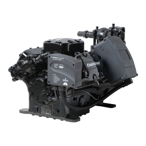
The CoreSense Diagnostics module utilizes proprietary
algorithms to protect the compressor and system from
repeated trips of system pressure controls and the
compressor internal overload. The protection terminal
of the module should be wired in series with the system
low pressure and high pressure cutouts, as well as
the compressor contactor. When the module detects
a series of trips as described below, it will activate a
lockout feature that opens the solid state switch in the
module, thereby cutting power to the contactor and de-
energizing the compressor.
Module LED Description
POWER LED (Green): indicates the module is
powered with 18 to 28 volts.
ALERT LED (Yellow): communicates an abnormal
systemconditionthroughauniqueashcode.The
ALERTLEDwillashanumberoftimesconsecutively,
pause and then repeat the process. The number of
consecutive ashes, dened as the Flash Code,
correlates to a particular abnormal condition. Detailed
descriptions of specic ALERT Flash Codes are
shown in Table 1.
TRIP/LOCK LED (Red): indicates either a TRIP or
LOCKcondition.
• TRIP: is indicated by a solid illumination of the
LED. This means the compressor is not running
and demand is present at the module.
• LOCK:isindicatedbyaashingLEDcorrelatingto
aLOCKconditioninwhichthemodulewillprevent
the compressor from starting.
Module Operation/Code Description
Code 1 – Long Run Time
The module will ash yellow one time when the
compressor operates for longer than 18 continuous
hours. This is an alert code only, and the module will
not lockout the compressor for this condition. This
code is inactive for heat-pumps.
Code 2 – Compressor (Pressure) Trips
The module will ash yellow two times when the
compressor operates from 12 seconds to 15 minutes
followed by a trip condition lasting longer than 7
minutes. When four consecutive or ten total Code
2 events are recorded, the module will lockout the
compressorandashredtwotimes.
Code 3 – Pressure Switch Cycling
The module will ash yellow three times when the
compressor operates from 12 seconds to 15 minutes
followed by a trip condition lasting between 35
seconds to 7 minutes. When four consecutive or ten
total Code 3 events are recorded, the module will
lockoutthecompressorandashredthreetimes.
Code 4 – Locked Rotor Trip
The module will ash yellow four times when the
compressor trips within 12 seconds of operation and
does not reset and start within 35 seconds. When ten
consecutive Code 4 events are recorded the module
willlockoutthecompressorandashredfourtimes.
Code 5 – Compressor (Moderate Run) Trip
The module will ash yellow ve times when the
compressor has operated between 15 minutes and
18 hours, followed by a compressor trip lasting longer
than 7 minutes. When four consecutive or ten total
Code 5 events are recorded, the module will lockout
thecompressorandashredvetimes.
Code 6 – Open Start Circuit
The module will lockout the compressor and ash
red six times if the module detects a demand signal
in the “Y” terminal and current in the “R” winding of
the compressor, but no current is detected in the “S”
winding of the compressor for 2 seconds.
Code 7 – Open Run Circuit
Themodulewilllockoutthecompressorandashred
seven times if the module detects a demand signal
in the “Y” terminal and current in the “S” winding of
the compressor, but no current is detected in the “R”
winding of the compressor for 2 seconds.
Code 8 – Welded Contactor
The module will ash yellow eight times if it has
detected line currents in the “S” and “R” windings and
demand is absent for 15 seconds.
