EKOM DK50 2V S User manual


DK50 PLUS, DK50 2V
05/2019 - 1 - NP-DK50 PLUS, 2V-7_05-2019-MD
CONTENTS
IMPORTANT INFORMATION................................................................................................................. 2
CONFORMITY WITH THE REQUIREMENTS OF EUROPEAN UNION DIRECTIVES............ 2
INTENDED USE......................................................................................................................... 2
CONTRAINDICATIONS AND SIDE-EFFECTS.......................................................................... 2
WARNINGS AND SYMBOLS..................................................................................................... 2
WARNINGS................................................................................................................................ 3
STORAGE AND TRANSPORT .................................................................................................. 5
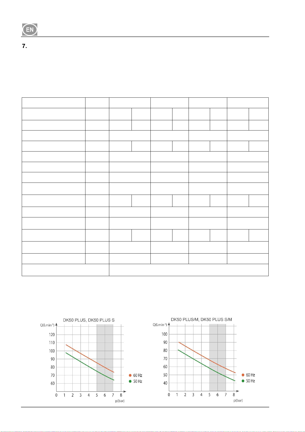
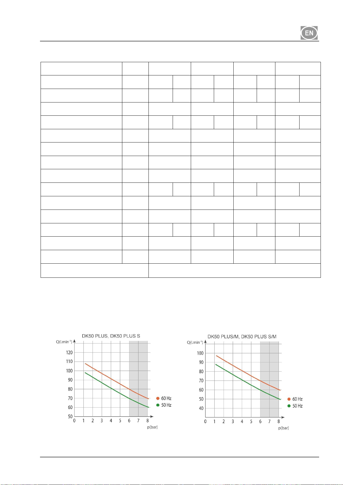
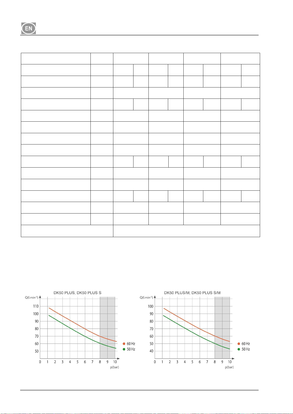
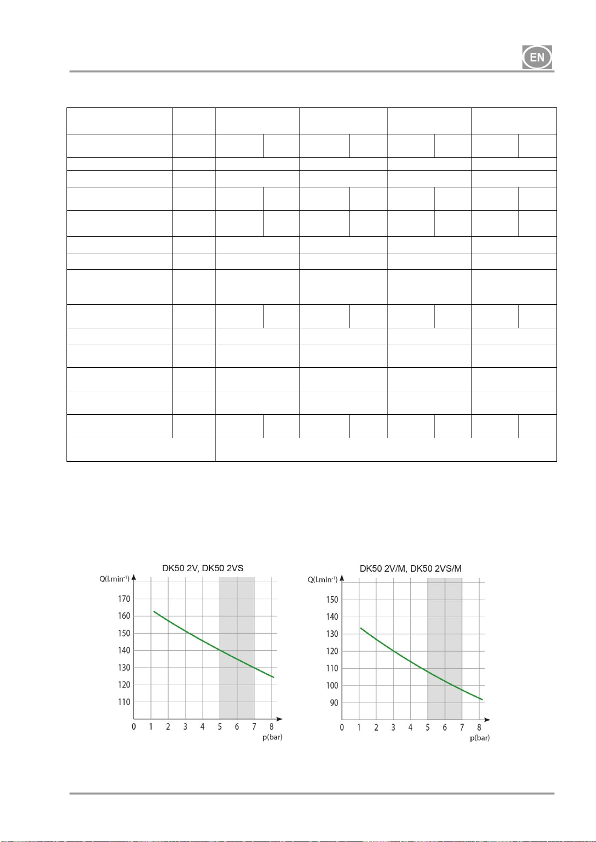
TECHNICAL DATA..................................................................................................................... 6
PRODUCT DESCRIPTION ......................................................................................................15
PRODUCT FUNCTIONALITY .................................................................................................. 16
PNEUMATIC DIAGRAM........................................................................................................... 20
INSTALLATION .................................................................................................................................... 21
CONDITIONS FOR USE .......................................................................................................... 21
PLACEMENT OF THE COMPRESSOR .................................................................................. 22
PNEUMATIC CONNECTIONS................................................................................................ 24
ELECTRICAL CONNECTIONS............................................................................................... 26
CONNECTION DIAGRAM........................................................................................................ 28
OPERATION ......................................................................................................................................... 31
COMMISSIONING....................................................................................................................31
SWITCHING THE COMPRESSOR ON ................................................................................... 32
COMPRESSOR SHUT-DOWN ................................................................................................32
MAINTENANCE.................................................................................................................................... 33
DEVICE MAINTENANCE......................................................................................................... 33
TROUBLESHOOTING.......................................................................................................................... 40
REPAIR SERVICE....................................................................................................................41
STORAGE ................................................................................................................................ 41
DISPOSAL OF THE DEVICE ................................................................................................... 41
ANNEX ................................................................................................................................................ 297
INSTALLATION RECORD...................................................................................................... 297

DK50 PLUS, DK50 2V
NP-DK50 PLUS, 2V-7_05-2019-MD - 2 - 05/2019
IMPORTANT INFORMATION
CONFORMITY WITH THE REQUIREMENTS OF EUROPEAN UNION DIRECTIVES
This product conforms to the requirements of the Medical Device Directive (93/42/EEC) and the
Machinery Directive (2006/42/EC), and is safe for the intended use if all safety instructions are
followed.
INTENDED USE
The compressor is used as a source of clean, oil-free compressed air to power dental unit,
instruments, and devices in laboratories where the parameters and properties of the compressed
air are suitable for the specific application.
Compressed air supplied by the compressor is unsuitable for use with artificial lung
ventilation devices without further filtration
Any other use of the product beyond its intended use is considered an incorrect use. The
manufacturer is not liable for any damages or injuries resulting from the incorrect use.
CONTRAINDICATIONS AND SIDE-EFFECTS
There are no contraindications or side-effects known.
WARNINGS AND SYMBOLS
The following symbols are used in the user manual, device and its packaging to denote important
details and information:
General warnings
Warning
Danger, electric shock hazard
Read the user manual!
CE-marking
Compressor is controlled automatically and may start without warning
Caution! Hot surface
Ground connection

DK50 PLUS, DK50 2V
05/2019 - 3 - NP-DK50 PLUS, 2V-7_05-2019-MD
Terminal for ground connection
Alternating current
Handling mark on package –FRAGILE
Handling mark on package –THIS SIDE UP
Handling mark on package –KEEP DRY
Handling mark on package –TEMPERATURE LIMITATIONS
Handling mark on package –LIMITED STACKING
Mark on package –RECYCLABLE MATERIAL
Manufacturer
WARNINGS
The product is designed and manufactured to be safe for the user and the surrounding environment
when used in the defined manner. Keep the following warnings in mind.
General warnings
READ THE USER MANUAL CAREFULLY BEFORE USING THE DEVICE AND KEEP IT FOR
FUTURE USE!
The user manual supports the correct installation, operation and maintenance of the product.
Careful review of this manual will provide the information necessary for the correct operation of
the product for its intended use.
Original packaging should be retained for the return of the device. Only the original packaging
ensures protection of the device during transport. If it is necessary to return the product during
the warranty period, the manufacturer is not liable for damages caused by improper packaging.
This warranty does not cover damages originating from the use of accessories other than those
specified or recommended by the manufacturer.
The manufacturer only guarantees the safety, reliability and function of the device if:
-installation, new settings, changes, expansion, and repairs are performed by the
manufacturer or an organisation authorised by the manufacturer.
-the product is used pursuant to the user manual.

DK50 PLUS, DK50 2V
NP-DK50 PLUS, 2V-7_05-2019-MD - 4 - 05/2019
The user manual corresponds to the configuration of the product and its compliance with the
applicable safety and technical standards at the time of printing. The manufacturer reserves all
rights for the protection of its configuration, methods and names.
Translation of the user manual is performed in accordance with the best available knowledge.
The Slovak version is to be used in the event of any uncertainties.
General safety warnings
The manufacturer designed and manufactured the product to minimise all risks when used correctly
for the intended use. The manufacturer considers it its obligation to lay down the following general
safety precautions.
Use and operation of the productmust comply with all laws and local regulations valid in the place
of use. The operator and user are responsible for following all the appropriate regulations in the
interests of performing work safely.
Only the use of original parts guarantees the safety of operating personnel and the flawless
operation of the product itself. Only the accessories and parts mentioned in the technical
documentation or expressly approved by the manufacturer should be used.
The operator must ensure that the device is functioning correctly and safely before every use.
The user must be familiar with the operation of the device.
Do not use the product in environments with a risk of explosion.
The user must inform the supplier immediately if any problem directly related to the operation of
the device occurs.
Safety warnings on protection from electric current
The device must only be connected to a properly installed, earthed socket.
Before the product is plugged in, ensure that the mains voltage and frequency stated on the
product are in compliance with the values of the mains.
Prior to putting the device into operation check for any damage to the connected pneumatic lines
and electrical wiring. Replace damaged pneumatic lines and electrical wirings immediately.
Immediately disconnect the product from the mains (remove power cord from the socket) in
hazardous situations or in the case of a technical malfunction.
During all repairs and maintenance, ensure that:
-the mains plug is removed from the power socket
-pressure is vented from the air tank and pipes
The product shall only be installed by a qualified technician.

DK50 PLUS, DK50 2V
05/2019 - 5 - NP-DK50 PLUS, 2V-7_05-2019-MD
STORAGE AND TRANSPORT
The compressor is shipped from the factory in a transport packaging. This protects the device from
damage during transport.
The original compressor packaging must be used for transport whenever possible.
Transport the compressor in an upright position, always secured with transport
fixation.
Protect the compressor from moisture, dirt and extreme temperatures during transport and
storage. Store the compressor in its original packaging in a warm, dry, and dust-free area.
Do not store near any chemical substances.
Keep the packaging material, if possible. If not, please dispose of the packaging material
in an environmentally-friendly way. Packaging cardboard can be recycled with old paper.
The compressor may only be transported when all air pressure has been vented.
Before moving or transporting the compressor, release all air pressure from the
tank and hoses and drain condensate from the air tank.
Storing or shipping the equipment in any conditions other than those specified
below is prohibited.
Ambient conditions for storage and transport
Products may only be stored and transported in vehicles that are free of any traces of volatile
chemicals under the following conditions:
Temperature: –25°C to +55°C, 24 h at up to +70°C
Relative humidity: 10% to 90% (non-condensing)

DK50 PLUS, DK50 2V
NP-DK50 PLUS, 2V-7_05-2019-MD - 6 - 05/2019
TECHNICAL DATA
Compressors are designed for dry and ventilated indoor environments with the following conditions:
Temperature : +5°C to +40°C,
Max. relative humidity.: 70%,
Max. absolute humidity. 15 g/m3
Tab.1
5 –7 bar
DK50 PLUS
DK50 PLUS S
DK50 PLUS/M
DK50 PLUS S/M
Nominal voltage /
frequency (*)
V / Hz
230 /
50/60
115 /
60
230 /
50/60
115 /
60
230 /
50/60
115 /
60
230 /
50/60
115 /
60
Performance at 5 bar
Lit.min-1
75/85
85
75/85
85
58/68
68
58/68
68
Working pressure (**)
bar
5.0 –7.0
5.0 –7.0
5.0 –7.0
5.0 –7.0
Max. current
A
3.8/4.8
8.9
3.9/4.9
9
3.9/4.9
9
4/5
9.1
Motor power
kW
0.55
0.55
0.55
0.55
Air tank volume
Lit.
25
25
25
25
Air quality –filtration
m
-
-
0.3
0.3
Maximum operating
pressure of safety valve
bar
8.0
8.0
8.0
8.0
Noise level at 5 bar
LpfA
[dB]
66/68
68
47/50
50
66/68
68
47/50
50
Duty cycle
100%
100%
100%
100%
PDP - drying performance
at 7 bar
-
-
+3°C
+3°C
Time to fill air tank from 0
to 6 bar
s
123/105
105
123/105
105
157/128
128
157/128
128
Dimensions (net)
w x d x h
mm
460x500x708
560x675x877
460x565x708
560x675x877
Net weight (***)
kg
48
87
53
92
Classification under
EN 60601-1
Class I.
Notes:
(*) When ordering, state the version of the compressor
(**) For other range of pressure:consult with the supplier
(***) Information about the weight is for informative purposes only and applies to the product without any
additional accessories.

DK50 PLUS, DK50 2V
05/2019 - 7 - NP-DK50 PLUS, 2V-7_05-2019-MD
Tab. 2
6 –8 bar
DK50 PLUS
DK50 PLUS S
DK50 PLUS/M
DK50 PLUS S/M
Nominal voltage / frequency
(*)
V / Hz
230 /
50/60
115 /
60
230 /
50/60
115 /
60
230 /
50/60
115 /
60
230 /
50/60
115 /
60
Performance
at 6 bar
Lit.min-1
70/80
80
70/80
80
60/70
70
60/70
70
Working pressure (**)
bar
6.0 –8.0
6.0 –8.0
6.0 –8.0
6.0 –8.0
Max. current
A
3.9/4.9
9
4/5
9.1
4/5
9.1
4.1/5.1
9.2
Motor power
kW
0.55
0.55
0.55
0.55
Air tank volume
Lit.
25
25
25
25
Air quality –filtration
m
-
-
0.3
0.3
Maximum operating pressure
of safety valve
bar
12.0
12.0
12.0
12.0
Noise level at 5 bar
LpfA
[dB]
66/68
68
47/50
50
66/68
68
47/50
50
Duty cycle
100%
100%
100%
100%
PDP drying performance at 7
bar
-
-
+3°C
+3°C
Time to fill air tank from 0 to 7
bar
s
149/126
126
149/126
126
198/159
159
198/159
159
Dimensions (net)
w x d x h
mm
460x500x708
560x675x877
460x565x708
560x675x877
Net weight (***)
kg
48
87
53
92
Classification under
EN 60601-1
Class I.
Notes:
(*) When ordering, state the version of the compressor
(**) For other range of pressure consult with the supplier
(***) Information about the weight is for informative purposes only and applies to the product without any
additional accessories.

DK50 PLUS, DK50 2V
NP-DK50 PLUS, 2V-7_05-2019-MD - 8 - 05/2019
Tab. 3
8 –10 bar
DK50 PLUS
DK50 PLUS S
DK50 PLUS/M
DK50 PLUS S/M
Nominal voltage / frequency
(*)
V / Hz
230 /
50/60
115 /
60
230 /
50/60
115 /
60
230 /
50/60
115 /
60
230 /
50/60
115 /
60
Performance
at 8 bar
Lit.min-1
60/70
70
60/70
70
50/60
60
50/60
60
Working pressure (**)
bar
8.0 –10.0
8.0 –10.0
8.0 –10.0
8.0 –10.0
Max. current
A
4.1/5.1
9.2
4.2/5.2
9.3
4.2/5.2
9.3
4.3/5.3
9.4
Motor power
kW
0.55
0.55
0.55
0.55
Air tank volume
Lit.
25
25
25
25
Air quality –filtration
m
-
-
0.3
0.3
Maximum operating pressure
of safety valve
bar
12.0
12.0
12.0
12.0
Noise level at 5 bar
LpfA
[dB]
66/68
68
47/50
50
66/68
68
47/50
50
Duty cycle
100%
100%
100%
100%
PDP drying performance at
7 bar
-
-
+3°C
+3°C
Time to fill air tank from 0 to
9 bar
s
208/176
176
208/176
176
304/239
239
304/239
239
Dimensions (net)
w x d x h
mm
460x500x708
560x675x877
460x565x708
560x675x877
Net weight (***)
kg
48
87
53
92
Classification under
EN 60601-1
Class I.
Notes:
(*) When ordering, state the version of the compressor
(**) For other range of pressure consult with the supplier
(***) Information about the weight is for informative purposes only and applies to the product without any
additional accessories.

DK50 PLUS, DK50 2V
05/2019 - 9 - NP-DK50 PLUS, 2V-7_05-2019-MD
Tab.4
5 –7 bar
DK50 2V
DK50 2VS
DK50 2V/M
DK50 2VS/M
Nominal voltage /
frequency (*)
V / Hz
230/50
3x400/50
230/60
115/60
230/50
3x400/50
230/60
115/60
230/50
3x400/50
230/60
115/60
230/50
3x400/50
230/60
115/60
Performance at 5 bar
Lit.min-1
140
140
108
108
Working pressure (**)
bar
5.0 –7.0
5.0 –7.0
5.0 –7.0
5.0 –7.0
Max. current
A
8.3
3.6
9.0
18.2
8.5
3.8
9.2
18.4
8.4
3.7
9.1
18.3
8.6
3.9
9.3
18.5
Motor power
kW
1.2
1.2
1.2
1.1
1.2
1.2
1.2
1.1
1.2
1.2
1.2
1.1
1.2
1.2
1.2
1.1
Air tank volume
Lit.
25
25
25
25
Air quality –filtration
m
-
-
0,3
0,3
Maximum operating
pressure of safety
valve
bar
8.0
8.0
8.0
8.0
Noise level at 5 bar
LpfA
[dB]
67
51.5
69.0
55.0
Duty cycle
100%
100%
100%
100%
PDP - drying
performance at 7 bar
-
-
+3°C
+3°C
Time to fill air tank
from 0 to 6 bar
s
52
52
65
65
Dimensions (net)
w x d x h
mm
460x500x709
560x675x877
460x565x709
560x675x877
Net weight (***)
kg
55
53
55
93
91
93
60
58
60
98
96
98
Classification under
EN 60601-1
Class I.
Notes:
(*) When ordering, state the version of the compressor
(**) For other range of pressure:consult with the supplier
(***) Information about the weight is for informative purposes only and applies to the product without any
additional accessories

DK50 PLUS, DK50 2V
NP-DK50 PLUS, 2V-7_05-2019-MD - 10 - 05/2019
Tab. 5
6 –8 bar
DK50 2V
DK50 2VS
DK50 2V/M
DK50 2VS/M
Nominal voltage /
frequency (*)
V / Hz
230/50
3x400/50
230/60
115/60
230/50
3x400/50
230/60
115/60
230/50
3x400/50
230/60
115/60
230/50
3x400/50
230/60
115/60
Performance
at 6 bar
Lit.min-1
135
135
104
104
Working pressure (**)
bar
6.0 –8.0
6.0 –8.0
6.0 –8.0
6.0 –8.0
Max. current
A
8.6
3.8
9.2
19.9
8.8
4.0
9.4
20.1
8.7
3.9
9.3
20.0
8.9
4.1
9.5
20.2
Motor power
kW
1.2
1.2
1.2
1.1
1.2
1.2
1.2
1.1
1.2
1.2
1.2
1.1
1.2
1.2
1.2
1.1
Air tank volume
Lit.
25
25
25
25
Air quality –filtration
m
-
-
0.3
0.3
Maximum operating
pressure of safety
valve
bar
12.0
12.0
12.0
12.0
Noise level at 5 bar
LpfA
[dB]
67
51.5
69.0
55.0
Duty cycle
100%
100%
100%
100%
PDP drying
performance at 7 bar
-
-
+3°C
+3°C
Time to fill air tank
from 0 to 7 bar
s
61
61
78
78
Dimensions (net)
w x d x h
mm
460x500x720
560x675x877
460x565x720
560x675x877
Net weight (****)
kg
55
53
55
93
91
93
60
58
60
98
96
98
Classification under
EN 60601-1
Class I.
Notes:
(*) When ordering, state the version of the compressor
(**) For other range of pressure consult with the supplier
(***) Weight of compressors with a KJF-1(KJF-2) unit _add 3(3.5) kg
(****) Information about the weight is for informative purposes only and applies to the product without any
additional accessories.

DK50 PLUS, DK50 2V
05/2019 - 11 - NP-DK50 PLUS, 2V-7_05-2019-MD
Tab. 6
8 –10 bar
DK50 2V
DK50 2VS
DK50 2V/M
DK50 2VS/M
Nominal voltage /
frequency (*)
V / Hz
230/50
3x400/50
230/60
115/60
230/50
3x400/50
230/60
115/60
230/50
3x400/50
230/60
115/60
230/50
3x400/50
230/60
115/60
Performance
at 8 bar
Lit.min-1
110
110
87
87
Working pressure (**)
bar
8.0 –10.0
8.0 –10.0
8.0 –10.0
8.0 –10.0
Max. current
A
8.4
4.6
9.3
18.6
8.6
4.8
9.5
18.8
8.5
4.7
9.4
18.7
8.7
4.9
9.6
18.9
Motor power
kW
1.2
1.2
1.2
1.1
1.2
1.2
1.2
1.1
1.2
1.2
1.2
1.1
1.2
1.2
1.2
1.1
Air tank volume
Lit.
25
25
25
25
Air quality –filtration
m
-
-
0.3
0.3
Maximum operating
pressure of safety
valve
bar
12,0
12,0
12,0
12,0
Noise level at 5 bar
LpfA
[dB]
67.0
51.5
69.0
55.0
Duty cycle
100%
100%
100%
100%
PDP drying
performance at 7 bar
-
-
+3°C
+3°C
Time to fill air tank
from 0 to 9 bar
s
96
96
123
123
Dimensions (net)
w x d x h
mm
460x500x720
560x675x877
460x565x720
560x675x877
Net weight (***)
kg
58
56
58
96
94
96
63
61
63
101
99
101
Classification under
EN 60601-1
Class I.
Notes:
(*) When ordering, state the version of the compressor
(**) For other range of pressure consult with supplier
(***) Information about the weight is for informative purposes only and applies to the product without any
additional accessories.

DK50 PLUS, DK50 2V
NP-DK50 PLUS, 2V-7_05-2019-MD - 12 - 05/2019
Free air delivery (FAD) correction due to elevation
FAD correction table
Elevation [mamsl]
0 - 1500
1501 - 2500
2501 - 3500
3501 - 4500
FAD [l/min]
FAD x 1
FAD x 0.8
FAD x 0.71
FAD x 0.60
FAD („Free Air Delivery“) output related to conditions:
Elevation: 0 MASL Temperature : 20°C
Atmospheric pressure : 101325 Pa Relative humidity : 0%
Electromagnetic compatibility declaration
Medical equipment needs special precautions regarding electromagnetic compatibility (EMC) and needs to
be installed and put into service according to the EMC information provided below.
Guidance and manufacturer's declaration - electromagnetic emissions
Pursuant to IEC 60601-1-2:2014 - Medical electrical equipment - Part 1-2: General requirements for
basic safety and essential performance - Collateral Standard: Electromagnetic disturbances
The equipment is intended for use in the electromagnetic environment specified below. The customer or the
user of the equipment should assure that it is used in such an environment.
Emissions test
Compliance
Electromagnetic environment - guidance
RF emissions CISPR 11
Group 1
The equipment uses RF energy only for its
internal functions. Therefore, the RF emissions
are very low and are not likely to cause any
interference in nearby electronic equipment.
RF emissions CISPR 11
Class B
The equipment is suitable for use in all
establishments, including domestic
establishments and those directly connected to
the public low voltage power supply
network that supplies buildings used for
domestic purposes.
Harmonic emissions IEC
61000-3-2
Class A
Voltage fluctuations/
flicker emissions IEC
61000-3-3
The equipment is not
likely to cause any flicker,
as the current flow is
approx. constant after the
start up.

DK50 PLUS, DK50 2V
05/2019 - 13 - NP-DK50 PLUS, 2V-7_05-2019-MD
Guidance and manufacturer's declaration - electromagnetic immunity
Pursuant to IEC 60601-1-2:2014 - Medical electrical equipment - Part 1-2: General requirements for
basic safety and essential performance - Collateral Standard: Electromagnetic disturbances
The equipment is intended for use in the electromagnetic environment specified below. The customer or the
user of the equipment should assure that it is used in such an environment.
Immunity test
IEC 60601-1-2
test level
Compliance level
Electromagnetic environment -
guidance
Electrostatic
discharge (ESD)
IEC 61000-4-2
±8 kV contact
±15 kV air
±8 kV contact
±15 kV air
Floors should be wood, concrete
or ceramic tile. If floors are covered
with synthetic material, the relative
humidity should be at least 30%.
Electrical fast
transient/burst
IEC 61000-4-4
±2 kV for power
supply
lines
±1 kV for
input/output lines
±2 kV
100 kHz repetition
frequency
Applied to mains
connection
Mains power quality should be
that of a typical commercial or hospital
environment.
Surge
IEC 61000-4-5
±1 kV differential
mode
±2 kV common
mode
±1 kV L-N
±2 kV L-PE; N-PE
Applied to mains
connection
Mains power quality should be that of
a typical commercial or hospital
environment.
Voltage dips,
short interruption,
and voltage
variations on
power
supply
input lines IEC
60601-4-11
UT=0%, 0,5 cycle
(at 0, 45, 90, 135,
180, 225, 270
and 315°)
UT=0%, 1 cycle
UT=70% 25/30
cycles (at 0°)
UT=0%, 250/300
cycles
UT=>95%, 0,5 cycle
(at 0, 45, 90, 135, 180,
225, 270 and 315°)
UT=>95%, 1 cycle
UT=70% (30% dipp
UT),
25(50Hz)/30(60Hz)
cycles (at 0°)
UT=>95%,
250(50Hz)/300(60Hz)
cycle
Mains power quality should be
that of a typical commercial or hospital
environment.
The device stops and restarts
automatically at each dip. In this case
does not occur unacceptable pressure
drop.
Power frequency
(50/60 Hz)
IEC 61000-4-8
N/A
N/A
The equipment does not contain
magnetically sensitive components or
circuits.
NOTE: UTis the A.C. mains voltage prior to application of the test level.

DK50 PLUS, DK50 2V
NP-DK50 PLUS, 2V-7_05-2019-MD - 14 - 05/2019
Guidance and manufacturer's declaration - electromagnetic immunity
Pursuant to IEC 60601-1-2:2014 - Medical electrical equipment - Part 1-2: General requirements for
basic safety and essential performance - Collateral Standard: Electromagnetic disturbances
The equipment is intended for use in the electromagnetic environment specified below. The customer or the
user of the equipment should assure that it is used in such an environment.
Immunity test
IEC 60601-1-2
test level
Compliance level
Electromagnetic environment - guidance
Conducted RF
IEC 61000-4-6
Radiated RF
IEC 61000-4-3
Proximity fields
from RF wireless
communications
equipment
IEC 61000-4-3
3 Vrms
150 kHz to 80MHz
3 V/m
80 MHz to 2,7
GHz
9 to 28 V/m
15 specific
frequencies
(380 to 5800 MHz)
3 Vrms
3 V/m
9 to 28 V/m
15 specific
frequencies
(380 to 5800
MHz)
Portable and mobile RF communications
equipment should be used no closer to any
part of the equipment, including cables,
than the recommended separation distance
calculated from the equation applicable to
the frequency of the transmitter.
Recommended separation distance
d=1,2√ P
d=1,2√ P, 80 MHz to 800 MHz
d=2,3√ P, 800 MHz to 2,7 GHz
where P is the maximum output power
rating of the transmitter in watts (W)
according to the transmitter manufacturer
and d is the recommended separation dis-
tance in metres (m).
Field strengths from fixed RF transmitters,
as determined by an electromagnetic site
survey a, should be less than the
compliance level in each frequency range b.
Interference may occur in the vicinity of
equipment marked with the following
symbol:
NOTE 1 At 80 MHz and 800 MHz, the higher frequency range applies.
NOTE 2 These guidelines may not apply in all situations. Electromagnetic propagation is affected by
absorption and reflection from structures, objects and people.
aField strengths from fixed transmitters, such as base stations for radio (cellular/cordless) telephones and
land mobile radios, amateur radio, AM and FM radio broadcast and TV broadcast cannot be predicted
theoretically with accuracy. To assess the electromagnetic environment due to fixed RF transmitters, an
electromagnetic site survey should be considered. If the measured field strength in the location in which
the equipment is used exceeds the applicable RF compliance level above, the equipment should be
observed to verify normal operation. If abnormal performance is observed, additional measures may be
necessary, such as re-orienting or relocating the equipment.
bOver the frequency range 150 kHz to 80 kHz, field strengths should be less than 3 V/m.

DK50 PLUS, DK50 2V
05/2019 - 15 - NP-DK50 PLUS, 2V-7_05-2019-MD
DK50 PLUS
DK50 PLUS S
DK50 2VS
DK50 2V
PRODUCT DESCRIPTION
Variants
Compressor models are designed in the following variants:
DK50 PLUS - a base-mounted compressor for stand-alone installation in a given room
DK50 PLUS/M - a base-mounted compressor with an air dryer.
DK50 PLUS S - a compressor in a cabinet with effective soundproofing for in-office installations
DK50 PLUS S/M- a compressor in a cabinet with an air dryer
DK50 2V - a base-mounted compressor for stand-alone installation in a given room
DK50 2V/M - a base-mounted compressor with an air dryer.
DK50 2VS - a compressor in a cabinet with effective soundproofing for in-office installations
DK50 2VS/M - a compressor in a cabinet with an air dryer
Accessories
Accessories not included in the standard order must be ordered separately!
8.2.1. Automatic condensate drain
The automatic condensate drain (AOK) automatically drains condensate from the compressor’s air
tank based on a pre-set time interval. The condensate drain (AOK) is a suitable accessory for
compressor models without dryers.
Type
Use
Kit article no.
AOK 11
DK50 PLUS, DK50 2V
447000001-047
8.2.2. Regulator set
Compressors may be equipped with a regulator set on the compressed air outlet if specified. The
regulator sets are suitable accessories for all the compressors specified above.
Type
Use
Kit article no.
REG11
DK50 PLUS, DK50 PLUS/M
DK50 2V, DK50 2V/M
447000001-077
8.2.3. Filters set
Compressors may be equipped with a filters set on the compressed air outlet if specified. The set of
filters may be equipped with a pressure regulator. The sets of filters are suitable accessories for the
compressors specified above.

DK50 PLUS, DK50 2V
NP-DK50 PLUS, 2V-7_05-2019-MD - 16 - 05/2019
NOTE : If a higher level of air filtration is required, this specification must be agreed on with the
supplier and made clear in the order.
Type
Use
Level of filtration / µm /
Pressure regulator
Kit article no.
FS 30FR
DK50 PLUS
DK50 2V
5
yes
447000001-079
FS 30M
5 + 0.3
no
447000001-080
FS 30MR
5 + 0.3
yes
447000001-081
FS 30S
5 + 0.3 + 0.01
no
447000001-082
FS 30SR
5 + 0.3 + 0.01
yes
447000001-083
FS 31S
DK50 PLUS/M
DK50 2V/M
0.3 + 0.01
no
447000001-086
FS 31SR
0.3 + 0.01
yes
447000001-087
FS 31SR2
0.01
yes
447000001-130
8.2.4. Condensation and filtration unit (KJF)
The compressor may be additionally fitted with a condensation and filtration unit (KJF-1, KJF-2 or
KJFR-1). The KJF-1, KJF-2 or KJFR-1 ensure that the compressed air from the air tank is cooled
in the cooler and the condensate is captured in the filter and automatically separated from the
pneumatic distribution system. The compressed air is filtered at the same time.
8.2.5. Equipotential bonding socket
The socket allows an equipotential bonding. (Fig. 12)
Type
Use
Name
Article no.
POAG-KBT6-EC
DK50 PLUS S,
DK50 PLUS S/M
DK50 2VS, DK50 2VS/M
Mains plug connector
033400075-000
FLEXI-S/POAG-HK6
Conductor (1 m)
034110083-000
PRODUCT FUNCTIONALITY
Compressor (Fig. 1)
The air pump (1) draws in atmospheric air through an inlet filter (8) and compresses it through a non-
return valve (3) into an air tank (2) from which the device draws compressed air. If the pressure in
the air tank drops to the switch-on pressure, the pressure switch (4) turns on the compressor and
the compressor supplies compressed air into the air tank until it reaches the switch-off pressure,
when the compressor switches off. The pressure hose is vented through the relief solenoid valve
(13) once the air pump is shut off. The safety valve (5) prevents the pressure in the air tank from
rising above the maximum allowed value. The drain valve (7) drains condensate from the air tank.
Compressed, oil-free filtered air is stored in the air tank ready for use.
Condensate must be drained from the air tank at regular intervals (see Chapter 19.1).
Compressor with membrane dryer (Fig. 2)
The air pump (1) draws in atmospheric air through an inlet filter (8) and compresses it, feeding it
through the coolers (14) and the filter (15) into the dryer (9) and the dry, clean air is then fed through
the non-return valve (3) into the air tank (2). A part of the air is released from the dryer with the
captured moisture, which is manifested as a light air stream along the body of the dryer (9).
Condensate from the filter is automatically drained at regular intervals into the collecting bottle via
the condensate drain solenoid valve (16). The dryer ensures continuous drying of the compressed
Type
Use
Level of filtration / µm /
Pressure regulator
Kit article no.
KJF-1
DK50 PLUS
DK50 2V
5
no
450001011-001
KJFR-1
yes
450001011-002
KJF-2
no
450001021-001

DK50 PLUS, DK50 2V
05/2019 - 17 - NP-DK50 PLUS, 2V-7_05-2019-MD
air. The drain valve (7) drains condensate from the air tank when drying performance is checked.
Compressed, oil-free filtered air is stored in the air tank ready for use.
The pressure vessel does not need to be drained.
Compressor cabinet (Fig. 3)
The soundproof cabinet provides compact covering of the compressor, allowing sufficient exchange
of cooling air. With its design It can be placed in a dentist’s office as a part of furniture. The fan under
the air pump of a compressor provides cooling of compressor and it is in operation at the same time
with an engine of the compressor. After prolonged use the temperature in the cabinet may rise
above 40°C, causing the cooling fan blower to automatically turn on. After cooling the cabinet area
down to 32°C the fan blower turns off automatically. Door of the casing with right opening may be
changed to left opening (see Chapter 12.2).
Make sure that nothing impedes the free flow of air under and around the
compressor. Never cover the hot air outlet on the top back side of the cabinet.
If placing the compressor on a soft floor such as carpet, create space for ventilation
between the base and floor or the cabinet and floor, e.g. underpin the footings with
hard pads.
The 8-10 bar compressor model is equipped with an hour counter.
Fig. 1 - DK50 PLUS - Compressor
Description for Figures 1-3
1. Air pump
2. Air tank
3. Non-return valve
4. Pressure switch
5. Safety valve
6. Pressure gauge
7. Drain valve
8. Inlet filter
9. Dryer
10. -
11. -
12. -
13. Solenoid valve
14. Dryer cooler
15. Filter
16. Condensate drain solenoid valve
17. Compressed air outlet
18. Circuit breaker switch
19. Bottle
20. Magnetic holder
21. Fan
22. Cabinet fan
23. Door pin
24. Rectifying screw
25. Lock
26. Supporting bracket
27. Wall stop
28. Switch
29. Pressure gauge
30. Door hinge
31. Handle
32. Casters
33. Pressure gauge hose
34. Socket
35. Cabinet connector with cord

DK50 PLUS, DK50 2V
NP-DK50 PLUS, 2V-7_05-2019-MD - 18 - 05/2019
Fig. 2 - DK50 2V/M - Compressor with dryer

DK50 PLUS, DK50 2V
05/2019 - 19 - NP-DK50 PLUS, 2V-7_05-2019-MD
Fig. 3 - Cabinet
Other manuals for DK50 2V S
4
This manual suits for next models
1
Table of contents
Languages:
Other EKOM Compressor manuals

EKOM
EKOM DK50 2V MOBILE MINI User manual

EKOM
EKOM DK50 2V S User manual

EKOM
EKOM DK50-3X4VR/M User manual

EKOM
EKOM DK50 D User manual

EKOM
EKOM DK50 4x2VT/M User manual

EKOM
EKOM DK50 DS User manual

EKOM
EKOM DK50 2V/50 User manual

EKOM
EKOM DK50 4x2VT/M User manual

EKOM
EKOM DK50 2V/50 User manual

EKOM
EKOM DK50 4x4VRT/M User manual
Popular Compressor manuals by other brands

Branick
Branick 7600 Installation, Operation & Repair Parts Information

SCANGRIP
SCANGRIP CANVIK CENTER operating instructions

mxr
mxr Dyna Comp Deluxe User manual/operation instructions

Sealey
Sealey RE2280 instructions

Panasonic
Panasonic Matsushita S51C90JAU6 Specification sheet

KAESER
KAESER BSD 40 Service manual