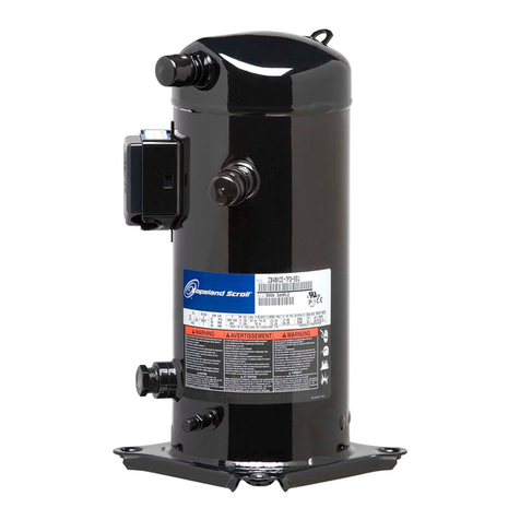
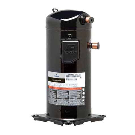
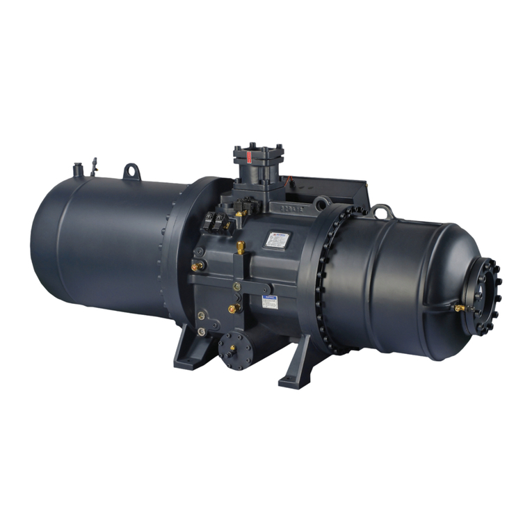
Emerson Copeland Scroll Digital ZRD36KRE Instruction Manual

Copeland Scroll Digital™Compressors
for comfort, precision and process cooling
ZRD36KRE to ZRD92KRE
Application Guidelines
Digital

C6.2.44/0219/E
About these guidelines ...............................................................................................1
1Safety instructions...........................................................................................1
1.1 Icon explanation............................................................................................................... 1
1.2 Safety statements ............................................................................................................ 1
1.3 General instructions......................................................................................................... 2
2Product description .........................................................................................3
2.1 Common information about Copeland Scroll Digital™ compressors............................... 3
2.2 Nomenclature................................................................................................................... 3
2.3 BOM Variation.................................................................................................................. 3
2.4 Dimensions ...................................................................................................................... 4
2.5 Application range ............................................................................................................. 6
2.5.1 Qualified refrigerants and oils .............................................................................. 6
2.5.2 Application limits and operating envelopes.......................................................... 6
3Installation........................................................................................................7
3.1 Compressor handling....................................................................................................... 7
3.1.1 Transport and storage.......................................................................................... 7
3.1.2 Positioning and securing...................................................................................... 7
3.1.3 Installation location............................................................................................... 7
3.1.4 Mounting parts...................................................................................................... 8
3.2 Solenoid valves for models ZRD*KRE compressors....................................................... 8
3.2.1 Solenoid valve installation –General recommendations..................................... 9
3.2.2 Solenoid valve installation –Tubing recommendations....................................... 9
3.3 Discharge check valve................................................................................................... 10
3.4 Brazing procedure.......................................................................................................... 10
3.5 Shut-off valves and adaptors......................................................................................... 11
3.6 Oil separator .................................................................................................................. 12
3.7 Accumulators ................................................................................................................. 12
3.8 Screens.......................................................................................................................... 12
3.9 Mufflers .......................................................................................................................... 12
3.10 Suction line noise and vibration..................................................................................... 13
4Electrical connection .....................................................................................14
4.1 General recommendations............................................................................................. 14
4.2 Electrical installation ...................................................................................................... 14
4.2.1 Terminal box....................................................................................................... 16
4.2.2 Motor winding..................................................................................................... 16
4.2.3 Motor protection ................................................................................................. 17
4.2.4 Protection devices.............................................................................................. 17
4.2.5 Crankcase heaters ............................................................................................. 17
4.3 Pressure safety controls ................................................................................................ 17
4.3.1 IPR valve (Internal Pressure Relief valve) ......................................................... 17
C6.2.44/0219/E
4.3.2 High-pressure control......................................................................................... 17
4.3.3 Low-pressure control.......................................................................................... 18
4.4 Discharge temperature protection ................................................................................. 18
4.5 High potential testing ..................................................................................................... 19
5Starting up & operation..................................................................................20
5.1 Strength pressure test.................................................................................................... 20
5.2 Tightness/pressure test.................................................................................................. 20
5.3 System evacuation......................................................................................................... 20
5.4 Preliminary checks –Pre-starting.................................................................................. 20
5.5 Charging procedure ....................................................................................................... 21
5.6 Initial start-up ................................................................................................................. 21
5.7 Rotation direction........................................................................................................... 21
5.8 Pressure fluctuations ..................................................................................................... 22
5.9 Starting sound................................................................................................................ 22
5.10 Deep vacuum operation................................................................................................. 22
5.11 Shell temperature........................................................................................................... 22
5.12 Pump-down cycle........................................................................................................... 22
5.13 Minimum run time .......................................................................................................... 22
5.14 Sound characteristics..................................................................................................... 23
5.15 Shut-off sound................................................................................................................ 23
5.16 Frequency...................................................................................................................... 23
5.17 Oil level .......................................................................................................................... 23
5.18 Digital system control..................................................................................................... 23
5.19 Power factor................................................................................................................... 23
6Maintenance & repair.....................................................................................24
6.1 Exchanging the refrigerant............................................................................................. 24
6.2 Rotalock valves.............................................................................................................. 24
6.3 Replacing a compressor................................................................................................ 24
6.3.1 Compressor replacement................................................................................... 24
6.3.2 Start-up of a new or replacement compressor................................................... 24
6.4 Lubrication and oil removal............................................................................................ 25
6.5 Oil additives ................................................................................................................... 25
6.6 Unbrazing system components ..................................................................................... 26
7Dismantling & disposal..................................................................................26
DISCLAIMER ..............................................................................................................26

C6.2.44/0219/E 1
About these guidelines
The purpose of these application guidelines is to provide guidance in the application of Copeland
Scroll™ compressors in users’ systems. They are intended to answer the questions raised while
designing, assembling and operating a system with these products.
Besides the support they provide, the instructions listed herein are also critical for the proper and
safe functioning of the compressors. Emerson will not guarantee the performance and reliability
of the product if it is misused in regard of these guidelines.
These application guidelines cover stationary applications only. For mobile applications, contact
Application Engineering as other considerations may apply.
1 Safety instructions
Copeland Scroll compressors are manufactured according to the latest European and US Safety
Standards. Particular emphasis has been placed on the user’s safety.
These compressors are intended for installation in systems in accordance with the Machinery
Directive MD 2006/42/EC and the Pressure Equipment Directive PED 2014/68/EU. They may be
put to service only if they have been installed in these systems according to instructions and
conform to the corresponding provisions of legislation. For relevant standards please refer to the
Manufacturer’s Declaration, available at www.climate.emerson.com/en-gb.
These instructions should be retained throughout the lifetime of the compressor.
You are strongly advised to follow these safety instructions.
1.1 Icon explanation
WARNING
This icon indicates instructions to
avoid personal injury and material
damage.
CAUTION
This icon indicates instructions to
avoid property damage and possible
personal injury.
High voltage
This icon indicates operations with a
danger of electric shock.
IMPORTANT
This icon indicates instructions to
avoid malfunction of the compressor.
Danger of burning or frostbite
This icon indicates operations with a
danger of burning or frostbite.
NOTE
This word indicates a
recommendation for easier operation.
Explosion hazard
This icon indicates operations with a
danger of explosion.
1.2 Safety statements
▪Refrigerant compressors must be employed only for their intended use.
▪Only qualified and authorized HVAC or refrigeration personnel are permitted to install,
commission and maintain this equipment.
▪Electrical connections must be made by qualified electrical personnel.
▪All valid standards for connecting electrical and refrigeration equipment must be
observed.
▪The national legislation and regulations regarding personnel protection must be
observed.
Use personal safety equipment. Safety goggles, gloves,
protective clothing, safety boots and hard hats should be worn
where necessary.

2 C6.2.44/0219/E
1.3 General instructions
WARNING
System breakdown! Personal injuries! Never install a system in the field
and leave it unattended when it has no charge, a holding charge, or with the
service valves closed without electrically locking out the system.
System breakdown! Personal injuries! Only approved refrigerants and
refrigeration oils must be used.
WARNING
High shell temperature! Burning! Do not touch the compressor until it has
cooled down. Ensure that other materials in the area of the compressor do not
get in touch with it. Lock and mark accessible sections.
CAUTION
Overheating! Bearing damage! Do not operate compressors without
refrigerant charge or without being connected to the system.
CAUTION
Contact with POE! Material damage! POE lubricant must be handled
carefully and the proper protective equipment (gloves, eye protection, etc.)
must be used at all times. POE must not come into contact with any surface
or material that it might damage, including without limitation, certain polymers,
eg, PVC/CPVC and polycarbonate.
IMPORTANT
Transit damage! Compressor malfunction! Use original packaging. Avoid
collisions and tilting.

C6.2.44/0219/E 3
2 Product description
2.1 Common information about Copeland Scroll Digital™ compressors
The Scroll compressor has been under development at Emerson since 1979. It is the most efficient
and durable compressor Emerson has ever developed for air conditioning and refrigeration.
These application guidelines deal with Copeland Scroll™Digital compressors for air
conditioning ZRD36KRE to ZRD92KRE. These compressors include a wide range of
capacities, electrical options and features.
Compressor
Cooling capacity [kW]
Motor
R450A
R513A
ZRD36KRE
2.55
3.00
PFJ/TFD
ZRD48KRE
3.47
4.09
TFD
ZRD61KRE
4.28
5.05
TFD
ZRD72KRE
5.14
6.03
TFD
ZRD92KRE
6.26
7.51
TFD
Table 1: Cooling capacity for ZRD*KRE compressors @ -10°C/45°C/10K/0K
Copeland Scroll Digital compressors have one scroll compression set driven by a single or three-
phase induction motor. The Scroll set is mounted at the upper end of the rotor shaft of the motor.
The rotor shaft axis is in the vertical plane.
2.2 Nomenclature
The model designation contains the following technical information about the compressor:
2.3 BOM Variation
The BOM (bill of material) number at the end of the compressor designation indicates the
compressor layout and details.
In general, there is one BOM version for the whole range of ZRD*KRE compressors:
BOM 455 braze connections, oil sight glass, oil service connection, IP21 t-box, no mounting
parts
Please refer to the Emerson price list for more details.

4 C6.2.44/0219/E
2.4 Dimensions
Compressor
model
A
[mm]
B
[mm]
C
[mm]
D
[mm]
E
[mm]
F
[mm]
G
[mm]
ØH
[mm]
ZRD36KRE
435.3
417.2
366.4
264.6
222.8
75.3
49.8
19
ZRD48KRE
466
448
397.1
294.1
252.5
75.3
49.8
22.2
ZRD61/72KRE
-
25.6
412.1
296.7
230.2-236.2
79.6
47.6
12.7
ZRD92KRE
-
129.7
412.1
296.7
230.2-236.2
79.6
47.6
19
Table 2: Dimensions Digital scroll ZRD*KRE
Figure 1: Dimensions of models ZRD36KRE & ZRD48KRE

C6.2.44/0219/E 5
Figure 2: Dimensions of models ZRD61KRE to ZRD92KRE

6 C6.2.44/0219/E
2.5 Application range
2.5.1 Qualified refrigerants and oils
IMPORTANT
It is essential that the glide of refrigerant blends (primarily R450A) be carefully
considered when adjusting pressure and superheat controls.
Oil recharge values can be taken from Copeland Scroll compressors brochures or Copeland™
brand products Select software at www.climate.emerson.com/en-gb.
Compressor
ZRD*KRE
Qualified refrigerants
R450A, R513A
Copeland™ brand products
standard oil
Emkarate RL 32 3MAF
Servicing oils
Emkarate RL 32 3MAF, Mobil EAL Arctic 22 CC
Table 3: Qualified refrigerants and oils
2.5.2 Application limits and operating envelopes
CAUTION
Inadequate lubrication! Compressor breakdown! The superheat at the
compressor suction inlet must always be sufficient to ensure that no refrigerant
droplets enter the compressor. For a typical evaporator-expansion valve
configuration a minimum stable superheat of at least 5K is required.
Application envelopes for the various refrigerants can be found in Select software, available at
www.climate.emerson.com/en-gb.

C6.2.44/0219/E 7
3 Installation
WARNING
High pressure! Injury to skin and eyes possible! Be careful when opening
connections on a pressurized item.
3.1 Compressor handling
3.1.1 Transport and storage
WARNING
Risk of collapse! Personal injuries! Move compressors only with
appropriate mechanical or handling equipment according to weight. Keep in
the upright position. Respect stacking loads according to Figure 3. Check the
tilting stability and if needed take action to ensure the stability of the stacked
loads. Keep the packaging dry at all times.
Respect the maximum number of identical packages which may be stacked on one
another, where "n" is the limiting number:
▪Transport: n = 1
▪Storage: n = 2
Figure 3: Maximum stacking loads for transport and storage
The compressor tilt angle should not be more than 30° during transport and handling. This will
prevent oil from exiting through the suction stub. A tilt angle of maximum 45° is allowed for a very
short time. Tilting the compressor more than 45° might affect its lubrication at start-up.
3.1.2 Positioning and securing
IMPORTANT
Handling damage! Compressor malfunction! Only use the lifting eyes
whenever the compressor requires positioning. If the compressor has two
lifting tabs, both must be used for lifting. Using discharge or suction
connections for lifting may cause damage or leaks.
If possible, the compressor should be kept vertical during handling.
The discharge connection plug should be removed first before pulling the suction connection plug
to allow the dry air pressure inside the compressor to escape. Pulling the plugs in this sequence
prevents oil mist from coating the suction tube making brazing difficult. The copper-coated steel
suction tube should be cleaned before brazing.
The compressor plugs must be removed as late as possible before brazing so that the air humidity
does not affect the oil characteristics.
As oil might spill out of the suction connection located low on the shell, the suction connection plug
must be left in place until the compressor is set into the unit.
No object, eg, a swaging tool should be inserted deeper than 51 mm into the suction tube as it
might damage the suction screen and motor.
3.1.3 Installation location
Scroll compressors are capable of operating correctly with compressor ambient humidity
between 30% and 95%. For correct operation the compressor ambient air temperatures have to
be between -40°C and 60°C and the compressor PS and TS have to be respected at all times
during operation and at a standstill.
Ensure that the compressors are installed on a solid level base. For single compressor application,
the compressor tilt angle during operation should not be more than 15° to allow adequate
lubrication. For multiple compressor parallel configurations, the compressors must be positioned
completely vertically on a totally horizontal surface or rail.

8 C6.2.44/0219/E
3.1.4 Mounting parts
Four vibration absorber grommets are supplied with each compressor. They dampen the start-up
surge of the compressor and minimise sound and vibration transmission to the compressor base
during operation. The metal sleeve inside is a guide designed to hold the grommet in place. It is
not designed as a load-bearing member, and application of excessive torque to the bolts can crush
the sleeve. Its inner diameter is approximately 8.5 mm to fit, eg, an M8 screw. The mounting torque
should be 13 ± 1 Nm. It is critically important for the grommet not to be compressed.
If the compressors are mounted in tandem or used in parallel, then the hard mountings (bolt M8
5/16") are recommended. The mounting torque should be 27 ± 1 Nm.
Mounting parts ZRD*KRE
Soft mountings
Figure 4: Mounting parts
3.2 Solenoid valves for models ZRD*KRE compressors
IMPORTANT
The external solenoid valve is a critical component for proper operation of
these compressors. Only the Emerson brand solenoid valve supplied as a
requested accessory must be used.
Due to the high life-cycle requirements in a hot gas environment, a special valve has been
developed. A screen is provided in the digital solenoid valve to prevent debris from disrupting valve
operation.
For reliability requirements, only Emerson-approved solenoid valves may be used for this
application. All compressor warranties are null and void if theEmerson-approved valve is not used.
For digital solenoid valve and complete tubing kits reference, see Emerson spare parts software
available at www.climate.emerson.com/en-gb.
Care must be taken during the brazing process that no solid parts can enter the control piston
compartment or the solenoid valve tubing. To prevent solid parts from entering the control valve
seat, the solenoid valve kit contains a filter screen.
The solenoid valve has to be fitted in such a way that the sleeve with the stem inside –which
supports the solenoid coil –is fixed and aligned in the upright position.
In case of compressor exchange, Emerson recommends replacing the high cycle digital solenoid
valve and coil at the same time.
For any defect around the digital solenoid valve, it is always good practise to exchange both the
solenoid valve and the coil.
Figure 5: Position of external solenoid valve without and with sound shell

C6.2.44/0219/E 9
3.2.1 Solenoid valve installation –General recommendations
▪The solenoid must be mounted vertically, within ± 15° of vertical. Horizontal mounting is not
permitted.
▪If a suction Rotalock fitting is used, the threaded shipping plug in the Rotalock fitting must be
removed prior to brazing in the vertical solenoid line.
▪The valve operation is directional. See Figure 6 below for inlet and outlet locations.
▪Do not restrict the line size coming from or leaving the solenoid. Use 3/8" soft drawn copper.
▪Mount the solenoid valve to the suction line. The tube from the solenoid to the suction should
be as short as possible, less than 3" (76 mm).
▪From the top cap to the solenoid a series of bends and/or shock loops are required to dampen
vibrations and resonance frequencies the assemblies might see during operation and start-
up. Solenoid tubing mounting kits including solenoid valves are available from Emerson.
▪The valve body contains a small filter mesh, to avoid large particles entering the inside (see
Figure 7), which could lead to a defect and blockage. The filter is part of the valve delivery
and already crimped inside; it cannot be changed. This is different from previous valve body
versions, where the filter was delivered loose to the valve body and could be exchanged.
▪The recommended tightening torque for the screw to fix the coil on the solenoid valve is
2 Nm.
Figure 6: Control valve without coil Figure 7: Control valve with coil
3.2.2 Solenoid valve installation –Tubing recommendations
IMPORTANT
This tube has been tested and qualified at 50 and 60 Hz operation for running
stresses and resonance in a single compressor lab environment. However, in
some compressor applications such as racks and transport applications, the
OEM is strongly advised to re-confirm the acceptability of the tube when the
compressor is subject to additional vibration inputs.
The tube from the solenoid to the suction, marked "A",
should be as short as possible (less than 7.5 cm).
Dimensions for a typical tube going from the top of the
compressor are shown in Figures 8 & 9.
Figure 8: Recommended piping

10 C6.2.44/0219/E
Figure 9: Control valve pipe connection
Emerson has developed digital solenoid tubing kits for compressors with brazing stub tubes or
with Rotalock connections and 24V or 230V coil –see Figures 10 & 11. The kits are optimized to
fit with or without sound shell and are valid for all compressor sizes using an external visible
solenoid valve.
For digital solenoid valve and complete tubing kits references, see Emerson spare parts software
available at www.climate.emerson.com/en-gb.
Figure 10: Piping kit for Rotalock connections Figure 11: Piping kit for stub tubes
3.3 Discharge check valve
There is no discharge check valve at the discharge port of ZRD*KRE digital compressors since
the high-side pressure is needed to support the operation of the unloader mechanism.
To avoid by-passing during the unloading process back to suction, a dynamic discharge valve is
fitted internally on the discharge port of the fixed scroll. This discharge valve cannot be used with
recycling pump-down because it is not leak-proof during the off period.
3.4 Brazing procedure
IMPORTANT
Blockage! Compressor breakdown! Maintain a flow of oxygen-free nitrogen
through the system at very low pressure during brazing. Nitrogen displaces
the air and prevents the formation of copper oxides in the system. If allowed
to form, the copper oxide material can later be swept through the system and
block screens such as those protecting capillary tubes, thermal expansion
valves, and accumulator oil return holes.
Contamination or moisture! Bearing failure! Do not remove the plugs until
the compressor is set into the unit. This minimises any entry of contaminants
and moisture.

C6.2.44/0219/E 11
The Copeland Scroll compressor versions with stub
tubes have copper-plated steel suction and
discharge tubes. These tubes are far more robust
and less prone to leaks than copper tubes. Due to
the different thermal properties of steel and copper,
brazing procedures may have to be changed from
those commonly used.
Refer to Figure 12 and the procedure below for the
brazing of the suction and discharge lines to a scroll
compressor.
▪The copper-coated steel tubes on scroll compressors can be brazed in approximately the
same manner as any copper tube.
▪Recommended brazing materials: any Silfos material is recommended, preferably with a
minimum of 5% silver. However, 0% silver is acceptable.
▪Be sure tube fitting inner diameter and tube outer diameter are clean prior to assembly.
▪Using a double-tipped torch, apply heat in area 1.
▪As the tube approaches brazing temperature, move the torch flame to area 2.
▪Heat area 2 until braze temperature is attained, moving the torch up and down and rotating
around the tube as necessary to heat the tube evenly. Add braze material to the joint while
moving the torch around the joint to flow braze material around the circumference.
▪After the braze material flows around the joint, move the torch to heat area 3. This will draw
the braze material down into the joint. The time spent heating area 3 should be minimal.
▪As with any brazed joint, overheating may be detrimental to the final result.
To disconnect:
▪Heat joint areas 2 and 3 slowly and uniformly until the braze material softens and the tube can
be pulled out of the fitting.
To reconnect:
▪Recommended brazing materials: Silfos with minimum 5% silver or silver braze used on other
compressors. Due to the different thermal properties of steel and copper, brazing procedures
may have to be changed from those commonly used.
3.5 Shut-off valves and adaptors
CAUTION
Leaking system! System breakdown! It is strongly recommended to
periodically re-torque all pipe and fixing connections to the original setting after
the system has been put into operation.
Figure 12
Figure 12: Suction tube brazing areas

12 C6.2.44/0219/E
Braze connections can be converted to Rotalock by means of adaptors. Rotalock shut-off valves
are available for the suction as well as the discharge side. Using either straight or angled adaptors
provides a way to convert a Rotalock into a brazing connection.
Refer to Table 4 for proper tightening torques:
Torque [Nm]
Rotalock 3/4" –16UNF
40-50
Rotalock 1" –14UNS
70-80
Rotalock 1 ¼" –12UNF
110-135
Rotalock 1 ¾" –12 UNF
135-160
Table 4
NOTE: More information about adaptors and shut-off valves can be found in the Emerson
spare parts software at www.climate.emerson.com/en-gb.
3.6 Oil separator
During any operating cycle of Copeland Scroll Digital compressors, there is a loaded state during
which the compressor operates at full capacity. The velocity of gas during this loaded state is
sufficient to return oil back to the compressor. Laboratory tests have established that there is no
problem in oil return, even when the length of the interconnecting pipe used is 100 metres and the
vertical elevation is 30 metres. Based on such performance, we do not strictly recommend the use
of an oil separator.
3.7 Accumulators
CAUTION
Inadequate lubrication! Bearing destruction! Minimise liquid refrigerant
returning to the compressor. Too much refrigerant dilutes the oil. Liquid
refrigerant can wash the oil off the bearings leading to overheating and bearing
failure.
Irrespective of system charge, oil dilution may occur if large amounts of liquid refrigerant
repeatedly flood back to the compressor during:
▪normal off cycles;
▪defrost;
▪varying loads.
In such a case an accumulator must be used to reduce flood-back to a safe level that the
compressor can handle. The use of accumulators is dependent on the application. If an
accumulator has to be used, the oil-return orifice should be from 1 to 1.4 mm in diameter for all
models covered in these guidelines, depending on compressor size and compressor flood-back
results.
The size of the accumulator depends upon the operating range of the system and the amount of
subcooling and subsequent head pressure allowed by the refrigerant control.
3.8 Screens
CAUTION
Screen blocking! Compressor breakdown! Use screens with at least
0.6 mm openings.
The use of screens finer than 30 x 30 mesh (0.6 mm openings) anywhere in the system should be
avoided with these compressors. Field experience has shown that finer mesh screens used to
protect thermal expansion valves, capillary tubes, or accumulators can become temporarily or
permanently plugged with normal system debris and block the flow of either oil or refrigerant to
the compressor. Such blockage can result in compressor failure.
3.9 Mufflers
External mufflers, normally applied to piston compressors in the past, may not be required for
Copeland Scroll compressors.

C6.2.44/0219/E 13
Individual system tests should be performed to verify acceptability of sound performance. If
adequate attenuation is not achieved, use a muffler with a larger cross-sectional area to inlet area
ratio. A ratio of 20:1 to 30:1 is recommended. A hollow shell muffler will work quite well. Locate
the muffler at minimum 15 cm to maximum 45 cm from the compressor for the most effective
operation. The farther the muffler is placed from the compressor within these ranges, the more
effective. Choose a muffler with a length of 10 to 15 cm.
3.10 Suction line noise and vibration
Copeland Scroll compressors inherently have low sound
and vibration characteristics. However in some respects
the sound and vibration characteristics differ from
reciprocating compressors and in rare instances could
result in unexpected sound generation. One difference is
that the vibration characteristic of the scroll compressor,
although low, includes two very close frequencies, one of
which is normally isolated from the shell by the suspension
of an internally-suspended compressor. These
frequencies, which are present in all compressors, may
result in a low-level "beat" frequency that can be detected
as noise coming along the suction line into the building
under some conditions. Elimination of the beat can be
achieved by attenuating either of the contributing
frequencies. This is easily done by using one of the
common combinations of recommended design
configurations. The scroll compressor makes both a rocking and twisting motion and enough
flexibility must be provided in the line to prevent vibration transmission into any lines attached to
the unit. In a split system, the most important goal is to ensure minimal vibration in all directions
at the service valve to avoid transmitting vibrations to the structure to which the lines are fastened.
A second difference of the Copeland Scroll compressor is that under some conditions the normal
rotational starting motion of the compressor can transmit an "impact" noise along the suction line.
This may be particularly pronounced in three-phase models due to their inherently higher starting
torque. This phenomenon, like the one described previously, also results from the lack of internal
suspension and can be easily avoided by using standard suction line isolation techniques as
described below. The sound phenomena described above are not usually associated with
reversible air conditioning / heat pump systems because of the isolation and attenuation provided
by the reversing valve and tubing bends.
Recommended configuration
▪Tubing configuration:........small shock loop
▪Service valve: ..................."angled valve" fastened to unit / wall
▪Suction muffler:.................not required
Alternative configuration
▪Tubing configuration:........small shock loop
▪Service valve: ..................."straight through" valve fastened to unit / wall
▪Suction muffler:.................may be required (acts as dampening mass)
Figure 13 Suction tube design

14 C6.2.44/0219/E
4 Electrical connection
4.1 General recommendations
The compressor terminal box has a wiring diagram on the inside of its cover. Before connecting
the compressor, ensure the supply voltage, the phases and the frequency match the nameplate
data.
4.2 Electrical installation
Single-phase (PF*) compressors:
Power circuit Control circuit
Motor terminal connections
Single-phase compressors are connected to the
Common (C), Start (S) and Run (R) connections
Legend
B1 ....... Room thermostat K1........Contactor
B3 ....... Discharge gas thermostat R2........Crankcase heater
C2....... Run capacitor S1........Auxiliary switch
F1 ....... Fuse
F3 ....... HP switch
F4 ....... LP switch
Figure 14

C6.2.44/0219/E 15
Three-phase compressors (TF*) with internal motor protection:
Power circuit Control circuit
Motor terminal connections
Three-phase compressors are connected to the T1,
T2 and T3 connections
Legend
B1 ....... Room thermostat K1........Contactor
B3 ....... Discharge gas thermostat R2........Crankcase heater
F1 ....... Fuse S1........Auxiliary switch
F3 ....... HP switch
F4 ....... LP switch
Figure 15

16 C6.2.44/0219/E
4.2.1 Terminal box
The standard terminal box is IP21 for all models with internal motor protection (TF*/PF*), enclosure
class according to IEC 60034-5.
Cable glands have an influence on the protection class of the terminal box. It is strongly
recommended to use appropriate cable glands in order to reach the rated protection class. We
advise installers/service providers to pay attention to this aspect every time they install or replace
a Copeland Scroll compressor and to use cable glands according to EN 50262 or any other
relevant standard of application in their country/region. Examples of correct electrical installations
are shown in Figures 16 & 17 below.
Figure 16: Correct electrical installation with cable glands for IP21 T-box (compressors ZRD36KRE & ZRD48KRE)
Figure 17: Correct electrical installation with cable glands for IP21 T-box (compressors ZRD61KRE to ZRD92KRE)
4.2.2 Motor winding
Compressor model ZRD36KRE is available in single-phase (PF*). The other ZRD*KRE models
are offered with three-phase (TF*) induction motors. Single-phase motors need a run capacitor
while all three-phase motors are connected in star.
The motor insulation material is class "B" for compressor models covered in these guidelines. This
is according to VDE 0530, IEC 34-18-1 or DIN 57530.

C6.2.44/0219/E 17
4.2.3 Motor protection
Conventional inherent internal line break motor protection is provided for all ZRD*KRE compressor
models.
4.2.4 Protection devices
Independently from the internal motor protection, fuses must be installed before the compressor.
The selection of fuses has to be carried out according to VDE 0635, DIN 57635, IEC 269-1 or
EN 60-269-1.
4.2.5 Crankcase heaters
IMPORTANT
Oil dilution! Bearing malfunction! Turn the crankcase heater on 12 hours
before starting the compressor.
A crankcase heater is used to prevent refrigerant migrating into the shell during standstill periods.
Due to the Copeland scroll’s inherent ability to handle liquid refrigerant in flooded conditions a
crankcase heater is not required when the system charge does not exceed the charge limits shown
in Table 5.
Compressor
Refrigerant
charge limit
ZRD36KRE & ZRD48KRE
3.6 kg
ZRD61KRE to ZRD92KRE
4.5 kg
Table 5
If a crankcase heater is fitted it is recommended
that the heater be turned on for a minimum of
12 hours prior to starting the compressor. This will
prevent oil dilution and bearing stress on initial
start-up. The crankcase heater must remain
energised during compressor off cycles.
The crankcase heater must be mounted below the
oil Schraeder valve located on the bottom shell
(see Figure 18).
The crankcase heater should be wired in such a way that it is turned on whenever the compressor
is switched off.
4.3 Pressure safety controls
4.3.1 IPR valve (Internal Pressure Relief valve)
The internal pressure relief valves for all ZRD*KRE compressors are located between the high
and low sides of the compressor. They are designed to open when the discharge-to-suction
differential pressure exceeds 26-31 bar. When the valve opens, hot discharge gas is routed back
into the area of the motor protector to cause a trip. During developmental blocked fan testing, it is
sometimes noted that the valve opens, but the compressor does not shut off while the discharge
pressure continues to climb. This condition is normally caused by floodback and may be corrected
by using a more restrictive expansion device or reducing the refrigerant charge.
4.3.2 High-pressure control
The cut-out setting for the high-pressure control shall be determined according to regional
standards, usually EN 378, part 2 in Europe.
The maximum pressure value for the individual compressor type, PS high side, is printed on the
nameplate of the compressor.
The high-pressure cut-out should have a manual reset feature for the highest level of system
protection.
Figure 18: Crankcase heater location
This manual suits for next models
4
Table of contents
Other Emerson Compressor manuals

Emerson
Emerson Copeland Scroll UltraTech CoreSense User guide

Emerson
Emerson XM670K 50 User manual

Emerson
Emerson Copeland Scroll QF115L User manual

Emerson
Emerson Copeland Stream 4MF-13X User manual

Emerson
Emerson Copeland Scroll Digital HLR Series Instruction Manual

Emerson
Emerson ZB Copeland Scroll User manual

Emerson
Emerson Copeland Scroll Series Instruction Manual

Emerson
Emerson Copeland Scroll ZR24KRE Instruction Manual