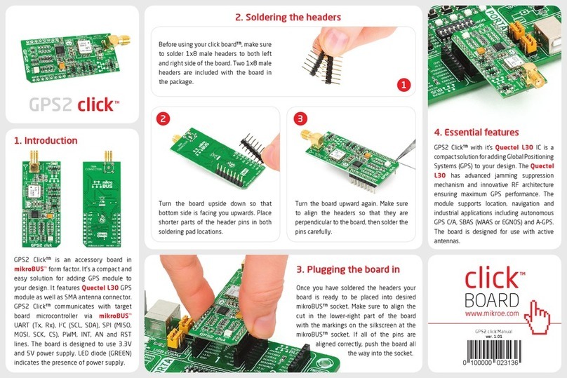
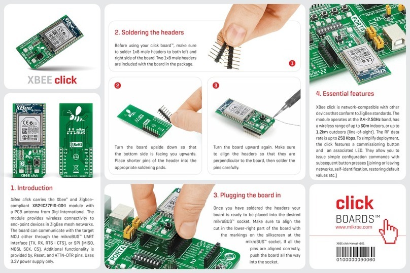
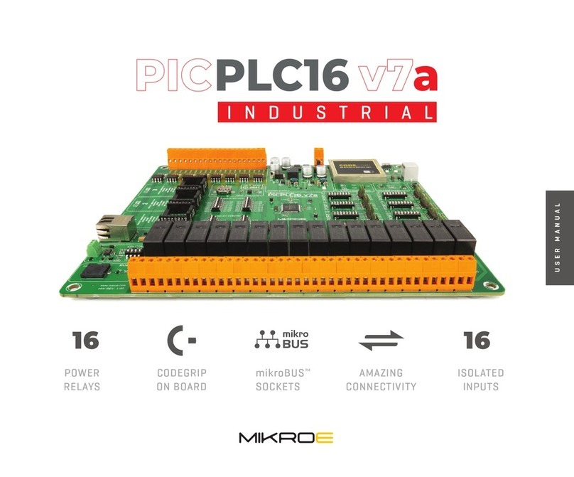
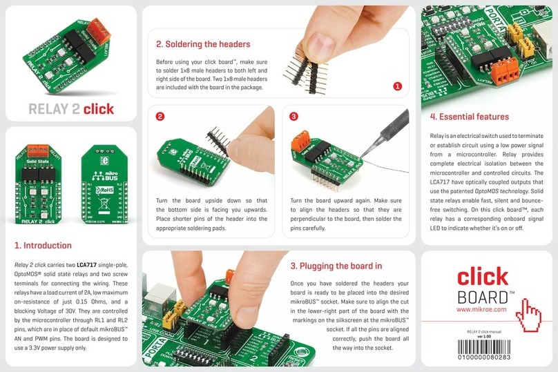
Mikroe SEMITECH N-PLC Click Installation and operating instructions

AN - MIKROE N-PLC Click Board User Guide v1.0 1
SM2400
MIKROE N-PLC Click Board User Guide
Application Note
September 22, 2023
This publication contains proprietary information which is subject to change without notice and is supplied ‘as is’, without any
warranty of any kind.

AN - MIKROE N-PLC Click Board User Guide v1.0 2
Table of Contents
1 Introduction............................................................................................................................................................3
2 Order Information ..................................................................................................................................................3
3 MIKROE Click Boards..............................................................................................................................................3
3.1 N-PLC Click bundle..........................................................................................................................................3
3.2 click USB adapter............................................................................................................................................4
4 Evaluation and Setup..............................................................................................................................................5
4.1 Connection .....................................................................................................................................................5
4.2 Evaluate G3-FCC ASCII Passthrough...............................................................................................................6
4.3 Evaluate G3-FCC GUI Passthrough.................................................................................................................8
4.4 Evaluate XXR ASCII Passthrough ................................................................................................................. 10
4.5 Evaluate XXR GUI Passthrough.................................................................................................................... 12
4.6 Evaluate G3-FCC MAC ................................................................................................................................. 14
Contact Information.................................................................................................................................................... 16

AN - MIKROE N-PLC Click Board User Guide v1.0 3
1INTRODUCTION
The N-PLC Click board is a Power-Line Communications (PLC) board designed by MIKROE based on the SM2400
universal Narrowband Power Line Communication (N-PLC) modem.
The N-PLC Click board can be ordered as a N-PLC Click bundle, which combines the N-PLC Click board with the N-
PLC Wall Adapter (110/220VAC), enabling performance testing of PLC communication over an AC mains network.
This adapter is also compatible with a wide range of AC plugs, which makes this bundle suitable for use in different
parts of the world.
Also, a click USB adapter is needed to be ordered separately to provide the power and the USB-to-UART interface
for the N-PLC Click board.
This document explains how to use MIKROE N-PLC Click bundle and click USB adapter as a SM2400 EVK to evaluate
various SM2400-based N-PLC solutions, including G3-PLC for FCC band and proprietary XXR modes, by loading
different firmware versions using the SM2400Control GUI.
2ORDER INFORMATION
•N-PLC Click bundle (PID: MIKROE-5677)
•click USB adapter (PID: MIKROE-1433)
•USB 2.0 type A to Mini-B cable (PID: MIKROE-2306)
3MIKROE CLICK BOARDS
3.1 N-PLC CLICK BUNDLE
This bundle provides a Narrowband Power Line Communication (N-PLC) solution that uses existing electrical
power lines to transmit data signals. It allows users to easily combine the N-PLC Click board based on the
programmable N-PLC transceiver from Semitech, the SM2400, with N-PLC Wall Adapter (power line
communication AC coupling circuit) to deliver a flexible and elegant solution for home automation and industrial
control applications.
Combining this board with the N-PLC Wall Adapter (110/220VAC) enables testing of PLC performance over an AC
mains network. This adapter comes with AC plug –EU. A wide range of AC plugs can be ordered separately from
MikroE website, which makes this bundle suitable for use in different parts of the world.
The N-PLC Click board can be powered in two ways –internally and externally. By default, the board power is
provided internally over the LM5158 boost converter in the value of 15V, which is obtained from the 5V
mikroBUS™power rail. When applying an external power supply of 15VDC on the VEXT terminal, the N-PLC Click
board will automatically be powered from the external source thanks to the protection of the converter, which
automatically recognizes the presence of the external power supply and gives it a priority.
The N-PLC Click board is designed for communication in the FCC band (approximately 154kHz –490kHz).
The bundle consists of:
•N-PLC Click
•N-PLC Wall Adapter

AN - MIKROE N-PLC Click Board User Guide v1.0 4
For more information about the N-PLC Click board, please visit MikroE website.
Figure 1 - N-PLC Click bundle
3.2 CLICK USB ADAPTER
The click USB adapter is a compact Shield board developed by MikroE that provides the necessary interface for
connecting Click boards™such as N-PLC Click board to a PC through the USB connection.
The click USB adapter is based on the FT2232H, a dual high-speed USB to a multipurpose UART/FIFO IC from FTDI
Chip. The FT2232H provides the necessary communication lines defined by the mikroBUS™standard. The
mikroBUS™host connector consists of two 1x8 female headers with SPI (MOSI, MISO, SCK, CS), I2C (SDA, SCL),
UART (Tx, Rx), RST, PWM, Analog and Interrupt lines as well as 3.3V, 5V, and GND power lines. The J1 jumper
selects whether UART or I2C interface will be used. For visual presentation, this board features a TX/RX LED that
will indicate the data transfer.
The click USB adapter board can be powered through a USB cable only. Onboard power circuitry generates 3.3V
and 5V. The latter can be used to power up the N-PLC Click board.
Note that some USB hubs are not able to supply sufficient current for the Click board to generate the 15V supply.
It is recommended connecting directly to the PC USB.
SM2400
PWD LED
PLC Signal Jack
Connector
MD1
PLC Signal Jack
3V3
External Power Supply
mikroBUSTM header
TX
RX

AN - MIKROE N-PLC Click Board User Guide v1.0 5
Figure 2 - click USB adapter
4EVALUATION AND SETUP
4.1 CONNECTION
•Plug one N-PLC Click board on the mikroBUSTM socket of a click USB adapter according to the pinout on
both boards.
•Plug the PLC Signal Jack of a N-PLC Wall Adapter to the N-PLC Click board.
•Connect the N-PLC Click board to a PC via a Mini USB cable.
•Repeat the above steps to the second set of N-PLC Click bundle and click USB adapter.
•For the initial test, plug both N-PLC Wall Adapters to the same power-strip which is not powered (cold
wire test) as shown in Figure 3.
•Register to the Semitech website, https://semitechsemi.com/register/, once it is approved and activated,
SM2400Control-ME GUI application can be downloaded from the Semitech website:
http://www.semitechsemi.com/solutions/sm9420.php.
mikroBUSTM socket
RX/TX LED Indicator
PWD LED Indicator
Mini USB Connector
FT2232H
I2C/UART Selection

AN - MIKROE N-PLC Click Board User Guide v1.0 6
Figure 3 - Connection
4.2 EVALUATE G3-FCC ASCII PASSTHROUGH
The N-PLC Click board comes pre-programmed with G3-FCC ASCII passthrough firmware. This means that the user
can send ascii messages from one board and receive them on another board by using any serial terminal (e.g., Tera
Term) with CR+LF and 115200 baud rate.
•Connect two N-PLC Click boards as shown in Figure 3.
•Check the COM port numbers from Device Manager and launch two Tera Term windows connected to the
COM port of each board.
•Set up the Serial Port for 115200 baud and set up the Terminal as shown in Figure 4.
USB
Windows PC
USB
Windows PC

AN - MIKROE N-PLC Click Board User Guide v1.0 7
Figure 4 - Tera Term Setups
•Type text from one Tera Term window and check the result from the other.
Figure 5 - Tx and Rx on Tera Term
•By default, the N-PLC Click boards are in ASCII passthrough data mode. The user can send ‘+++’ to change
it to the command mode and send ATO to switch back to data mode. The supported list of AT commands
can be obtained by typing AT&H command in command mode, as shown in Figure 6.

AN - MIKROE N-PLC Click Board User Guide v1.0 8
Figure 6 - Tx/Rx text via Tera Term
4.3 EVALUATE G3-FCC PASSTHROUGH
SM2400Control-ME GUI application is a convenient tool to test and experiment with PLC performance. It can be
downloaded from the Semitech website: http://www.semitechsemi.com/solutions/sm9420.php and used by
performing the following steps:
•Connect two N-PLC Click boards as shown in Figure 3.
•Launch SM2400Control-ME.exe to open two GUI windows.
•Open the Terminal from Tool > Terminal; select ASCII, Add CR+LF and then send ‘+++’ to enter command
mode and send ‘ATX’ command to exit ASCII mode (enter GUI mode) as shown in Figure 7.
Figure 7 - Commands to exit ASCII mode

AN - MIKROE N-PLC Click Board User Guide v1.0 9
•From the main GUI, Configuration tab, click ‘Get Proto’. The GUI will recognize the G3 FCC FW as shown in
Figure 8.
•Repeat the same process to 2nd N-PLC Click bundle.
•Send 100 packets from Tx Test of one GUI and check the received packets from Rx Test of another GUI as
shown in Figure 8. RSSI and SNR can also be found in the Rx GUI.
Figure 8 - G3 FCC GUI Tx/Rx
Note: SM2400Control-ME GUI should be able to automatically connect to the click USB adapter, as shown in
Figure 8. If not, from Configuration tab, click Disconnect, browse to find the right COM port (e.g., COM5) and then
click Connect as shown in Figure 9.

AN - MIKROE N-PLC Click Board User Guide v1.0 10
Figure 9 - Connection to the GUI via COM port
4.4 EVALUATE XXR ASCII PASSTHROUGH
The users can evaluate XXR ASCII passthrough by the following steps:
•Connect two N-PLC Click boards as shown in Figure 3.
•Launch SM2400Control-ME.exe to open two GUI windows.
•From Tools > Terminal, send ‘+++’ to enter command mode and then send ‘ATX’ command to exit ASCII
mode.
•From the main GUI, FWupgrade tab, browse to find img-passthru-xxr-evk2-2023.08.28-7651-master-
a574e039.image, and then click Wr Image to upgrade the firmware to XXR ASCII Passthrough as shown in
Figure 10.
Figure 10 - FW Upgrade
•Once FW upgrade complete is displayed, click Get Proto from Configuration tab. The GUI will be changed
to XXR ASCII passthrough appearance as shown in Figure 11.

AN - MIKROE N-PLC Click Board User Guide v1.0 11
Figure 11 - GUI in XXR ASCII Mode
•Repeat the same process to 2nd N-PLC Click bundle.
•Open Tools > Terminals for both N-PLC Click bundles, select ASCII, Add CR+LF and then send ascii text and
check the result on the 2nd Terminal as shown in Figure 12.
Figure 12 - XXR ASCII passthrough Tx/Rx text via Terminal

AN - MIKROE N-PLC Click Board User Guide v1.0 12
The user can also use other serial terminals, e.g., Tera Term for this test.
4.5 EVALUATE XXR GUI PASSTHROUGH
•When both N-PLC click bundles are in the XXR ASCII passthrough mode, from Tools > Terminal, send ‘+++’
to enter command mode and then send ‘ATX’ command to exit ASCII mode.
•From main GUI, Configuration tab, click Get Proto. The GUI will recognize the XXR FW as shown in Figure
13.
Figure 13 - XXR GUI Mode
•Send 100 packets from Tx Test of one GUI and check the received packets from Rx Test of another GUI.

AN - MIKROE N-PLC Click Board User Guide v1.0 13
Figure 14 - XXR GUI Tx/Rx
Note:
•The user can change the XXR settings as described in Section 6.3.2 of AN - Semitech SM2400 EVK User
Guide-4_0.pdf.
•Please note that the N-PLC bundles will go back to the default ASCII passthrough mode after power
cycle/reconnect the USB cable.

AN - MIKROE N-PLC Click Board User Guide v1.0 14
4.6 EVALUATE G3-FCC MAC
•Power cycle (reconnect Mini USB cable).
•From Tools > Terminal, send ‘+++’ to enter command mode and then send ‘ATX’ to exit ASCII mode.
•From FWupgrade tab, browse to find img-g3-fcc-mac-evk2-2023.08.28-7651-master-a574e039.image and
then click Wr Image to upgrade the firmware to G3-FCC MAC.
•From Configuration tab, click Get Proto. The GUI will recognize the G3 MAC mode as shown in Figure 15.
Figure 15 - G3-PLC MAC GUI
•Repeat the same process to 2nd N-PLC Click bundle.
•From GUI #1, set Short Address as 0001 and click Set; and then set PAN ID as 0000, click Set.
•From GUI #2, set Short Address as 0002 and click Set; and then set PAN ID as 0000, click Set.
•Send message from GUI #1 to Destination Address 0002 and check the received message on GUI #2 as
shown in Figure 16.

AN - MIKROE N-PLC Click Board User Guide v1.0 15
Figure 16 - G3-PLC MAC Tx/Rx
The user can refer to Section 6.43 of AN - Semitech SM2400 EVK User Guide-4_0.pdf for details about G3-PLC MAC
evaluations.

AN - MIKROE N-PLC Click Board User Guide v1.0 16
CONTACT INFORMATION
For additional information regarding the MikroE N-PLC click board or SM2400 modules including technical data
sheets, application notes, sample enquiries, demonstration modules, pricing and ordering, please contact:
Semitech Semiconductor Pty. Ltd.
http://www.semitechsemi.com

AN - MIKROE N-PLC Click Board User Guide v1.0 17
Revision History
Revision
Number
Date
Description
0.1
21/08/2023
Initial draft
1.0
22/09/2023
Initial release

AN - MIKROE N-PLC Click Board User Guide v1.0 18
CORPORATE OFFICE
Semitech Semiconductor Pty Ltd
Kensington, VIC 3031
Australia
Phone: +61 3 9372 6655
Email: [email protected]
www.semitechsemi.com
© 2023 Semitech Semiconductor. All rights reserved. / Rev. AN - MIKROE N-PLC Click Board User Guide - Sep-23
Disclaimer: Semitech Semiconductor makes no warranty for the use of its products, other than those expressly contained in the Company's standard warranty which is detailed in Semitech Terms and Conditions
located on the Company's web site. The Company assumes no responsibility for any errors which may appear in this document, reserves the right to change devices or specifications detailed herein at any time
without notice, and does not make any commitment to update the information contained herein. No licenses to patents or other intellectual property of Semitech are granted by the Company in connection
with the sale of Semitech products, expressly or by implication. Semitech products are not authorized for use as critical components in life support devices or systems.
This manual suits for next models
1
Table of contents
Other Mikroe Microcontroller manuals