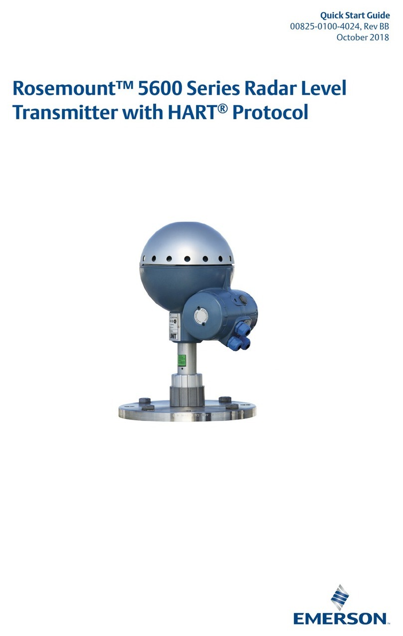
Emerson 3308A Rosemount 3308 Series User manual

Reference Manual
00809-0100-4308, Rev BA
December 2014
Rosemount 3308 Series
Wireless Guided Wave Radar, 3308A
Reference Manual


Reference Manual
00809-0100-4308, Rev BA
Title Page
December 2014
iii
Rosemount 3308 Series Wireless
Guided Wave Radar Level Transmitter
NOTICE
Read this manual before working with the product. For personal and system safety, and for
optimum product performance, make sure you thoroughly understand the contents before
installing, using, or maintaining this product.
The United States has two toll-free assistance numbers and one international number.
Customer Central
1-800-999-9307 (7:00 a.m. to 7:00 p.m. CST)
North American Response Center
1-800-654-7768 (24 hours a day)
Equipment service needs
International
1-952-906-8888
Explosions could result in death or serious injury.
Verify that the operating environment of the gauge is consistent with the appropriate
hazardous locations certifications.
Installation of device in an explosive environment must be in accordance with appropriate
local, national and international standards, codes, and practices.
Ensure device is installed in accordance with intrinsically safe or non-incendive field
practices.

iv
Reference Manual
00809-0100-4308, Rev BA
Title Page
December 2014
Electrical shock can result in death or serious injury.
Ground device on non-metallic tanks (e.g. fiberglass tanks) to prevent electrostatic charge
build-up.
Single lead probes are sensitive for strong electromagnetic fields and therefore not suitable
for non-metallic tanks.
Care must be taken during transportation of power module to prevent electrostatic charge
build-up.
Device must be installed to ensure a minimum antenna separation distance of 8 in. (20 cm)
from all persons.
Probes covered with plastic and/or with plastic discs may generate an ignition-capable level
of electrostatic charge under certain extreme conditions. Therefore, when the probe is
used in a potentially explosive atmosphere, appropriate measures must be taken to prevent
electrostatic discharge.
Process leaks could result in death or serious injury.
Only qualified personnel should install the equipment.
Install transmitter prior to process start-up.
Install and tighten process connectors before applying pressure.
Handle the transmitter carefully.
Do not remove the transmitter while in operation.
If the process seal is damaged, gas could escape from the tank when removing the
transmitter head from the probe.
Any substitution of non-recognized parts may jeopardize safety. Repair, e.g. substitution of
components etc., may also jeopardize safety and is under no circumstances allowed.

v
Reference Manual
00809-0100-4308, Rev BA
Title Page
December 2014
This device complies with Part 15 of the FCC Rules. Operation is subject to the following
conditions: This device may not cause harmful interference. This device must accept any
interference received, including interference that may cause undesired operation. This
device must be installed to ensure a minimum antenna separation distance of 20 cm (8 in.)
from all persons.
The products described in this document are NOT designed for nuclear-qualified
applications.
Using non-nuclear qualified products in applications that require nuclear-qualified
hardware or products may cause inaccurate readings.
For information on Rosemount nuclear-qualified products, contact your local Emerson
Process Management Sales Representative.
NOTICE
Power Module Considerations
Each Power Module contains two "C" size primary lithium/thionyl chloride batteries. Each
battery contains approximately 2.5 grams of lithium, for a total of 5 grams in each pack.
Under normal conditions, the battery materials are self-contained and are not reactive as
long as the batteries and the pack integrity are maintained. Care should be taken to prevent
thermal, electrical or mechanical damage. Contacts should be protected to prevent
premature discharge.
Battery hazards remain when cells are discharged.
Power modules should be stored in a clean and dry area. For maximum battery life, storage
temperature should not exceed 30° C.
The Power Module may be replaced in a hazardous area. The Power Module has surface
resistivity greater than one gigaohm and must be properly installed in the wireless device
enclosure. Care must be taken during transportation to and from the point of installation to
prevent electrostatic charge build-up.

vi
Reference Manual
00809-0100-4308, Rev BA
Title Page
December 2014

i
Reference Manual
00809-0100-4308, Rev BA
Table of Contents
December 2014
Table of Contents
1Section 1: Introduction
1.1 Service support. . . . . . . . . . . . . . . . . . . . . . . . . . . . . . . . . . . . . . . . . . . . . . . . . . . . . . . . .1
1.2 Product recycling/disposal . . . . . . . . . . . . . . . . . . . . . . . . . . . . . . . . . . . . . . . . . . . . . . .1
2Section 2: Transmitter Overview
2.1 Theory of operation. . . . . . . . . . . . . . . . . . . . . . . . . . . . . . . . . . . . . . . . . . . . . . . . . . . . .3
2.2 Emerson's Smart Wireless. . . . . . . . . . . . . . . . . . . . . . . . . . . . . . . . . . . . . . . . . . . . . . . .6
2.3 Application characteristics . . . . . . . . . . . . . . . . . . . . . . . . . . . . . . . . . . . . . . . . . . . . . . .6
2.3.1 Tank shape. . . . . . . . . . . . . . . . . . . . . . . . . . . . . . . . . . . . . . . . . . . . . . . . . . . . . . .6
2.3.2 In-tank obstructions. . . . . . . . . . . . . . . . . . . . . . . . . . . . . . . . . . . . . . . . . . . . . . .7
2.3.3 Interface level measurement . . . . . . . . . . . . . . . . . . . . . . . . . . . . . . . . . . . . . . .7
2.4 Application examples . . . . . . . . . . . . . . . . . . . . . . . . . . . . . . . . . . . . . . . . . . . . . . . . . . .8
2.5 Components of the transmitter . . . . . . . . . . . . . . . . . . . . . . . . . . . . . . . . . . . . . . . . . .9
2.6 Probe selection guide for the Rosemount 3308 Series Transmitter . . . . . . . . . . .10
3Section 3: Installation
3.1 Safety messages. . . . . . . . . . . . . . . . . . . . . . . . . . . . . . . . . . . . . . . . . . . . . . . . . . . . . . .13
3.2 Installation procedure . . . . . . . . . . . . . . . . . . . . . . . . . . . . . . . . . . . . . . . . . . . . . . . . . .16
3.3 Review mounting considerations . . . . . . . . . . . . . . . . . . . . . . . . . . . . . . . . . . . . . . . .17
3.3.1 Recommended mounting position . . . . . . . . . . . . . . . . . . . . . . . . . . . . . . . . .17
3.3.2 Flange connection on nozzles . . . . . . . . . . . . . . . . . . . . . . . . . . . . . . . . . . . . .19
3.3.3 Non-metallic tanks . . . . . . . . . . . . . . . . . . . . . . . . . . . . . . . . . . . . . . . . . . . . . . .19
3.4 Review mounting preparations . . . . . . . . . . . . . . . . . . . . . . . . . . . . . . . . . . . . . . . . . .20
3.4.1 Measure tank height . . . . . . . . . . . . . . . . . . . . . . . . . . . . . . . . . . . . . . . . . . . . .20
3.4.2 Shorten the probe. . . . . . . . . . . . . . . . . . . . . . . . . . . . . . . . . . . . . . . . . . . . . . . .21
3.4.3 Mount a centering disc for pipe installations. . . . . . . . . . . . . . . . . . . . . . . . .26
3.5 Anchor the probe . . . . . . . . . . . . . . . . . . . . . . . . . . . . . . . . . . . . . . . . . . . . . . . . . . . . . .30
3.5.1 Flexible single/twin lead probe. . . . . . . . . . . . . . . . . . . . . . . . . . . . . . . . . . . . .30
3.5.2 Rigid single lead probe. . . . . . . . . . . . . . . . . . . . . . . . . . . . . . . . . . . . . . . . . . . .31
3.5.3 Coaxial probe. . . . . . . . . . . . . . . . . . . . . . . . . . . . . . . . . . . . . . . . . . . . . . . . . . . .31
3.6 Mount device on tank . . . . . . . . . . . . . . . . . . . . . . . . . . . . . . . . . . . . . . . . . . . . . . . . . .33
3.6.1 Threaded tank connection . . . . . . . . . . . . . . . . . . . . . . . . . . . . . . . . . . . . . . . .33
3.6.2 Tank connection with flange . . . . . . . . . . . . . . . . . . . . . . . . . . . . . . . . . . . . . .34
3.6.3 Tank connection with loose flange (“plate design”) . . . . . . . . . . . . . . . . . .35
3.6.4 Tank connection with Tri-Clamp . . . . . . . . . . . . . . . . . . . . . . . . . . . . . . . . . . .36
3.7 Ground the device . . . . . . . . . . . . . . . . . . . . . . . . . . . . . . . . . . . . . . . . . . . . . . . . . . . . .37
Contents

ii
Reference Manual
00809-0100-4308, Rev BA
Table of Contents
December 2014
Table of Contents
3.8 Install the power module . . . . . . . . . . . . . . . . . . . . . . . . . . . . . . . . . . . . . . . . . . . . . . .38
3.9 Position the antenna . . . . . . . . . . . . . . . . . . . . . . . . . . . . . . . . . . . . . . . . . . . . . . . . . . .38
3.10Utilize the device display . . . . . . . . . . . . . . . . . . . . . . . . . . . . . . . . . . . . . . . . . . . . . . .39
3.10.1Rotate the device display . . . . . . . . . . . . . . . . . . . . . . . . . . . . . . . . . . . . . . . . .39
3.10.2Retrofitting . . . . . . . . . . . . . . . . . . . . . . . . . . . . . . . . . . . . . . . . . . . . . . . . . . . . .39
4Section 4: Configuration
4.1 Overview . . . . . . . . . . . . . . . . . . . . . . . . . . . . . . . . . . . . . . . . . . . . . . . . . . . . . . . . . . . . .41
4.2 Safety messages. . . . . . . . . . . . . . . . . . . . . . . . . . . . . . . . . . . . . . . . . . . . . . . . . . . . . . .42
4.3 Configuration procedure . . . . . . . . . . . . . . . . . . . . . . . . . . . . . . . . . . . . . . . . . . . . . . .44
4.4 Get started with your preferred configuration tool . . . . . . . . . . . . . . . . . . . . . . . . .45
4.4.1 AMS Wireless Configurator (version 12.0 or later is required) . . . . . . . . . .45
4.4.2 Field Communicator. . . . . . . . . . . . . . . . . . . . . . . . . . . . . . . . . . . . . . . . . . . . . .47
4.5 Join device to wireless network . . . . . . . . . . . . . . . . . . . . . . . . . . . . . . . . . . . . . . . . . .48
4.5.1 Power up the wireless device . . . . . . . . . . . . . . . . . . . . . . . . . . . . . . . . . . . . . .48
4.5.2 Connect to device. . . . . . . . . . . . . . . . . . . . . . . . . . . . . . . . . . . . . . . . . . . . . . . .50
4.5.3 Configure Update Rate . . . . . . . . . . . . . . . . . . . . . . . . . . . . . . . . . . . . . . . . . . .51
4.5.4 Obtain Network ID and Join Key. . . . . . . . . . . . . . . . . . . . . . . . . . . . . . . . . . . .52
4.5.5 Enter Network ID and Join Key . . . . . . . . . . . . . . . . . . . . . . . . . . . . . . . . . . . . .52
4.5.6 Verify device joins network. . . . . . . . . . . . . . . . . . . . . . . . . . . . . . . . . . . . . . . .53
4.6 Configure device using Guided Setup . . . . . . . . . . . . . . . . . . . . . . . . . . . . . . . . . . . .57
4.6.1 Connect to device. . . . . . . . . . . . . . . . . . . . . . . . . . . . . . . . . . . . . . . . . . . . . . . .57
4.6.2 Basic Setup. . . . . . . . . . . . . . . . . . . . . . . . . . . . . . . . . . . . . . . . . . . . . . . . . . . . . .58
4.6.3 Optional Setup . . . . . . . . . . . . . . . . . . . . . . . . . . . . . . . . . . . . . . . . . . . . . . . . . .58
4.7 Verify Level . . . . . . . . . . . . . . . . . . . . . . . . . . . . . . . . . . . . . . . . . . . . . . . . . . . . . . . . . . .59
5Section 5: Operation
5.1 Safety messages. . . . . . . . . . . . . . . . . . . . . . . . . . . . . . . . . . . . . . . . . . . . . . . . . . . . . . .61
5.2 Device display screen messages . . . . . . . . . . . . . . . . . . . . . . . . . . . . . . . . . . . . . . . . .63
5.2.1 Variable screens . . . . . . . . . . . . . . . . . . . . . . . . . . . . . . . . . . . . . . . . . . . . . . . . .63
5.2.2 Diagnostic button screen sequence . . . . . . . . . . . . . . . . . . . . . . . . . . . . . . . .64
5.3 View measurement values . . . . . . . . . . . . . . . . . . . . . . . . . . . . . . . . . . . . . . . . . . . . . .66
5.3.1 View current measurement values . . . . . . . . . . . . . . . . . . . . . . . . . . . . . . . . .66
5.3.2 View trends . . . . . . . . . . . . . . . . . . . . . . . . . . . . . . . . . . . . . . . . . . . . . . . . . . . . .66
5.3.3 Interpret measurement status bars. . . . . . . . . . . . . . . . . . . . . . . . . . . . . . . . .66
5.4 Check Device Status . . . . . . . . . . . . . . . . . . . . . . . . . . . . . . . . . . . . . . . . . . . . . . . . . . .67

iii
Reference Manual
00809-0100-4308, Rev BA
Table of Contents
December 2014
Table of Contents
6Section 6: Service and Troubleshooting
6.1 Safety messages. . . . . . . . . . . . . . . . . . . . . . . . . . . . . . . . . . . . . . . . . . . . . . . . . . . . . . .69
6.2 Alert messages . . . . . . . . . . . . . . . . . . . . . . . . . . . . . . . . . . . . . . . . . . . . . . . . . . . . . . . .72
6.2.1 Device display alerts. . . . . . . . . . . . . . . . . . . . . . . . . . . . . . . . . . . . . . . . . . . . . .72
6.2.2 Alert messages in AMS Wireless Configurator and Field Communicator .74
6.3 Troubleshooting guide . . . . . . . . . . . . . . . . . . . . . . . . . . . . . . . . . . . . . . . . . . . . . . . . .78
6.3.1 Incorrect level readings . . . . . . . . . . . . . . . . . . . . . . . . . . . . . . . . . . . . . . . . . . .78
6.3.2 Incorrect or missing interface level reading. . . . . . . . . . . . . . . . . . . . . . . . . .80
6.3.3 Power module troubleshooting. . . . . . . . . . . . . . . . . . . . . . . . . . . . . . . . . . . .81
6.3.4 Device display troubleshooting . . . . . . . . . . . . . . . . . . . . . . . . . . . . . . . . . . . .81
6.3.5 Wireless Network troubleshooting . . . . . . . . . . . . . . . . . . . . . . . . . . . . . . . . .82
6.4 Service and troubleshooting tools . . . . . . . . . . . . . . . . . . . . . . . . . . . . . . . . . . . . . . .83
6.4.1 Reading the Echo Curve. . . . . . . . . . . . . . . . . . . . . . . . . . . . . . . . . . . . . . . . . . .83
6.4.2 Adjusting thresholds . . . . . . . . . . . . . . . . . . . . . . . . . . . . . . . . . . . . . . . . . . . . .84
6.4.3 Viewing Measurement History. . . . . . . . . . . . . . . . . . . . . . . . . . . . . . . . . . . . .89
6.4.4 Reviewing Network Join Status and Details . . . . . . . . . . . . . . . . . . . . . . . . . .89
6.4.5 Locating the device . . . . . . . . . . . . . . . . . . . . . . . . . . . . . . . . . . . . . . . . . . . . . .90
6.4.6 Using the Simulation Mode. . . . . . . . . . . . . . . . . . . . . . . . . . . . . . . . . . . . . . . .91
6.5 Application challenges . . . . . . . . . . . . . . . . . . . . . . . . . . . . . . . . . . . . . . . . . . . . . . . . .91
6.5.1 Resolving thin oil layers . . . . . . . . . . . . . . . . . . . . . . . . . . . . . . . . . . . . . . . . . . .91
6.5.2 Handling disturbances at the top of the tank . . . . . . . . . . . . . . . . . . . . . . . .92
6.5.3 Interface measurements with fully submerged probes. . . . . . . . . . . . . . . .96
6.5.4 Noise or weak surface echoes. . . . . . . . . . . . . . . . . . . . . . . . . . . . . . . . . . . . . .97
6.6 Power module replacement. . . . . . . . . . . . . . . . . . . . . . . . . . . . . . . . . . . . . . . . . . . . .97
6.7 Transmitter head replacement . . . . . . . . . . . . . . . . . . . . . . . . . . . . . . . . . . . . . . . . . .99
6.8 Probe replacement . . . . . . . . . . . . . . . . . . . . . . . . . . . . . . . . . . . . . . . . . . . . . . . . . . 100
AAppendix A: Reference Data
A.1 Functional specifications . . . . . . . . . . . . . . . . . . . . . . . . . . . . . . . . . . . . . . . . . . . . . 101
A.1.1 General . . . . . . . . . . . . . . . . . . . . . . . . . . . . . . . . . . . . . . . . . . . . . . . . . . . . . . . 101
A.1.2 Wireless . . . . . . . . . . . . . . . . . . . . . . . . . . . . . . . . . . . . . . . . . . . . . . . . . . . . . . 101
A.1.3 Display and configuration . . . . . . . . . . . . . . . . . . . . . . . . . . . . . . . . . . . . . . . 102
A.1.4 Temperature limits. . . . . . . . . . . . . . . . . . . . . . . . . . . . . . . . . . . . . . . . . . . . . 103
A.1.5 Process temperature and pressure rating . . . . . . . . . . . . . . . . . . . . . . . . . 104
A.1.6 Interface measurements . . . . . . . . . . . . . . . . . . . . . . . . . . . . . . . . . . . . . . . . 106
A.2 Performance specifications . . . . . . . . . . . . . . . . . . . . . . . . . . . . . . . . . . . . . . . . . . . 107
A.2.1 General . . . . . . . . . . . . . . . . . . . . . . . . . . . . . . . . . . . . . . . . . . . . . . . . . . . . . . . 107

iv
Reference Manual
00809-0100-4308, Rev BA
Table of Contents
December 2014
Table of Contents
A.2.2 Environment . . . . . . . . . . . . . . . . . . . . . . . . . . . . . . . . . . . . . . . . . . . . . . . . . . 107
A.2.3 Accuracy over measuring range. . . . . . . . . . . . . . . . . . . . . . . . . . . . . . . . . . 108
A.2.4 Maximum measuring range and minimum dielectric constant . . . . . . . 110
A.2.5 Interface measuring range . . . . . . . . . . . . . . . . . . . . . . . . . . . . . . . . . . . . . . 110
A.2.6 Viscosity and Coating/Build-up . . . . . . . . . . . . . . . . . . . . . . . . . . . . . . . . . . 111
A.3 Physical specifications. . . . . . . . . . . . . . . . . . . . . . . . . . . . . . . . . . . . . . . . . . . . . . . . 111
A.3.1 Material selection . . . . . . . . . . . . . . . . . . . . . . . . . . . . . . . . . . . . . . . . . . . . . . 111
A.3.2 Tank connection and probe . . . . . . . . . . . . . . . . . . . . . . . . . . . . . . . . . . . . . 111
A.3.3 Engineered solutions . . . . . . . . . . . . . . . . . . . . . . . . . . . . . . . . . . . . . . . . . . . 115
A.3.4 Chamber/pipe installations. . . . . . . . . . . . . . . . . . . . . . . . . . . . . . . . . . . . . . 115
A.4 Ordering information . . . . . . . . . . . . . . . . . . . . . . . . . . . . . . . . . . . . . . . . . . . . . . . . 119
A.5 Spare parts and accessories . . . . . . . . . . . . . . . . . . . . . . . . . . . . . . . . . . . . . . . . . . . 124
A.6 Dimensional drawings. . . . . . . . . . . . . . . . . . . . . . . . . . . . . . . . . . . . . . . . . . . . . . . . 131
BAppendix B: Product Certifications
B.1 Safety messages. . . . . . . . . . . . . . . . . . . . . . . . . . . . . . . . . . . . . . . . . . . . . . . . . . . . . 139
B.2 Product certifications . . . . . . . . . . . . . . . . . . . . . . . . . . . . . . . . . . . . . . . . . . . . . . . . 141
B.2.1 European Union Directive Information. . . . . . . . . . . . . . . . . . . . . . . . . . . . 141
B.2.2 Approved manufacturing locations. . . . . . . . . . . . . . . . . . . . . . . . . . . . . . . 141
B.2.3 ATEX Directives (94/9/EC). . . . . . . . . . . . . . . . . . . . . . . . . . . . . . . . . . . . . . . 141
B.2.4 Electro Magnetic Compatibility (EMC) (2004/108/EC) . . . . . . . . . . . . . . 141
B.2.5 Radio and Telecommunications Terminal Equipment Directive
(R&TTE) (1999/5/EC) . . . . . . . . . . . . . . . . . . . . . . . . . . . . . . . . . . . . . . . . . . . 141
B.2.6 Telecommunication Compliance. . . . . . . . . . . . . . . . . . . . . . . . . . . . . . . . . 141
B.2.7 FCC and IC . . . . . . . . . . . . . . . . . . . . . . . . . . . . . . . . . . . . . . . . . . . . . . . . . . . . 142
B.2.8 Ordinary Location Certification for FM Approvals. . . . . . . . . . . . . . . . . . . 142
B.2.9 Pressure Equipment Directive (PED) . . . . . . . . . . . . . . . . . . . . . . . . . . . . . . 142
B.2.10Hazardous Locations Certificates . . . . . . . . . . . . . . . . . . . . . . . . . . . . . . . . 143
B.2.11Other certifications . . . . . . . . . . . . . . . . . . . . . . . . . . . . . . . . . . . . . . . . . . . . 147
B.3 Approval drawings . . . . . . . . . . . . . . . . . . . . . . . . . . . . . . . . . . . . . . . . . . . . . . . . . . . 148
CAppendix C: High Gain Remote Antenna Option
C.1 Safety messages. . . . . . . . . . . . . . . . . . . . . . . . . . . . . . . . . . . . . . . . . . . . . . . . . . . . . 151
C.2 Functional and physical specifications . . . . . . . . . . . . . . . . . . . . . . . . . . . . . . . . . . 152
C.2.1 General . . . . . . . . . . . . . . . . . . . . . . . . . . . . . . . . . . . . . . . . . . . . . . . . . . . . . . . 152
C.2.2 Wireless . . . . . . . . . . . . . . . . . . . . . . . . . . . . . . . . . . . . . . . . . . . . . . . . . . . . . . 152
C.2.3 Coaxial cable . . . . . . . . . . . . . . . . . . . . . . . . . . . . . . . . . . . . . . . . . . . . . . . . . . 152
C.2.4 RF Lightning Arrestor . . . . . . . . . . . . . . . . . . . . . . . . . . . . . . . . . . . . . . . . . . . 152

v
Reference Manual
00809-0100-4308, Rev BA
Table of Contents
December 2014
Table of Contents
C.2.5 Mounting bracket. . . . . . . . . . . . . . . . . . . . . . . . . . . . . . . . . . . . . . . . . . . . . . 152
C.2.6 Antenna . . . . . . . . . . . . . . . . . . . . . . . . . . . . . . . . . . . . . . . . . . . . . . . . . . . . . . 152
C.3 Review installation considerations . . . . . . . . . . . . . . . . . . . . . . . . . . . . . . . . . . . . . 153
C.3.1 Antenna mounting . . . . . . . . . . . . . . . . . . . . . . . . . . . . . . . . . . . . . . . . . . . . . 153
C.3.2 Antenna height . . . . . . . . . . . . . . . . . . . . . . . . . . . . . . . . . . . . . . . . . . . . . . . . 153
C.3.3 Affix coaxial cable . . . . . . . . . . . . . . . . . . . . . . . . . . . . . . . . . . . . . . . . . . . . . . 153
C.3.4 Install coaxial drip loop . . . . . . . . . . . . . . . . . . . . . . . . . . . . . . . . . . . . . . . . . 153
C.3.5 Apply coaxial sealant moisture protection. . . . . . . . . . . . . . . . . . . . . . . . . 153
C.4 Transient/lightning considerations. . . . . . . . . . . . . . . . . . . . . . . . . . . . . . . . . . . . . 153
C.4.1 Gateway transient protection . . . . . . . . . . . . . . . . . . . . . . . . . . . . . . . . . . . 153
C.4.2 RF lightning arrestor ground connection . . . . . . . . . . . . . . . . . . . . . . . . . . 153
C.5 Install the high gain remote antenna . . . . . . . . . . . . . . . . . . . . . . . . . . . . . . . . . . . 154
DAppendix D: Configuration Parameters
D.1 Safety messages. . . . . . . . . . . . . . . . . . . . . . . . . . . . . . . . . . . . . . . . . . . . . . . . . . . . . 157
D.2 Menu overview of the Device Descriptor (DD) . . . . . . . . . . . . . . . . . . . . . . . . . . . 159
D.3 Configuration parameters . . . . . . . . . . . . . . . . . . . . . . . . . . . . . . . . . . . . . . . . . . . . 160
D.3.1 Guided Setup. . . . . . . . . . . . . . . . . . . . . . . . . . . . . . . . . . . . . . . . . . . . . . . . . . 160
D.3.2 Manual Setup - Device . . . . . . . . . . . . . . . . . . . . . . . . . . . . . . . . . . . . . . . . . . 164
D.3.3 Manual Setup - Level . . . . . . . . . . . . . . . . . . . . . . . . . . . . . . . . . . . . . . . . . . . 168
D.3.4 Alert Setup . . . . . . . . . . . . . . . . . . . . . . . . . . . . . . . . . . . . . . . . . . . . . . . . . . . . 173
D.3.5 Echo Tuning . . . . . . . . . . . . . . . . . . . . . . . . . . . . . . . . . . . . . . . . . . . . . . . . . . . 176
EAppendix E: Mapping of Alert Messages in the HART command
48 Additional Status Field
E.1 Alert messages and descriptions. . . . . . . . . . . . . . . . . . . . . . . . . . . . . . . . . . . . . . . 179

vi
Reference Manual
00809-0100-4308, Rev BA
Table of Contents
December 2014
Table of Contents

Reference Manual
00809-0100-4308, Rev BA
Section 1: Introduction
December 2014
1
Introduction
Section 1 Introduction
1.1 Service support
To expedite the return process outside of the United States, contact the nearest Emerson
Process Management representative.
Within the United States, call the Emerson Process Management Instrument and Valves
Response Center using the 1-800-654-RSMT (7768) toll-free number. This center, available 24
hours a day, will assist you with any needed information or materials.
The center will ask for product model and serial numbers, and will provide a Return Material
Authorization (RMA) number. The center will also ask for the process material to which the
product was last exposed. Emerson Process Management Instrument and Valves Response
Center representatives will explain the additional information and procedures necessary to
return goods exposed to hazardous substances.
1.2 Product recycling/disposal
Recycling of equipment and packaging should be taken into consideration and disposed in
accordance with local and national legislation/regulations.
Individuals who handle products exposed to a hazardous substance can avoid injury if they
are informed of and understand the hazard. If the product being returned was exposed to
a hazardous substance as defined by Occupational Safety and Health Administration
(OSHA), a copy of the required Material Safety Data Sheet (MSDS) for each hazardous
substance identified must be included with the returned goods.
NOTICE
Shipping considerations for wireless products.
The unit was shipped to you without the Power Module installed. Please remove the Power
Module prior to shipping the unit.
Each Power Module contains two "C" size primary lithium/thionyl chloride batteries. Primary
lithium batteries (charged or discharged) are regulated during transportation by the U.S.
Department of Transportation. They are also covered by IATA (International Air Transport
Association), ICAO (International Civil Aviation Organization), and ARD (European Ground
Transportation of Dangerous Goods). It is the responsibility of the shipper to ensure
compliance with these or any other local requirements. Consult current regulations and
requirements before shipping.

2
Reference Manual
00809-0100-4308, Rev BA
Section 1: Introduction
December 2014
Introduction

Reference Manual
00809-0100-4308, Rev BA
Section 2: Transmitter Overview
December 2014
3Transmitter Overview
Section 2 Transmitter Overview
Theory of operation . . . . . . . . . . . . . . . . . . . . . . . . . . . . . . . . . . . . . . . . . . . . . . . . . . . . . . . . . page 3
Emerson's Smart Wireless . . . . . . . . . . . . . . . . . . . . . . . . . . . . . . . . . . . . . . . . . . . . . . . . . . . . page 6
Application characteristics . . . . . . . . . . . . . . . . . . . . . . . . . . . . . . . . . . . . . . . . . . . . . . . . . . . page 6
Application examples . . . . . . . . . . . . . . . . . . . . . . . . . . . . . . . . . . . . . . . . . . . . . . . . . . . . . . . page 8
Components of the transmitter . . . . . . . . . . . . . . . . . . . . . . . . . . . . . . . . . . . . . . . . . . . . . . . page 9
Probe selection guide for the Rosemount 3308 Series Transmitter . . . . . . . . . . . . . . . . page 10
2.1 Theory of operation
The Rosemount 3308 Series is the first true wireless level transmitter that is based on the Time
Domain Reflectometry (TDR) principle. Low power nano-second-pulses are guided along a
probe submerged in the process media. When a pulse reaches the surface of the material it is
measuring, part of the energy is reflected back to the transmitter, and the time difference
between the generated and reflected pulse is converted into a distance from which the total
level or interface level is calculated (see Figure 2-1).
The reflectivity of the product is a key parameter for measurement performance. A high
dielectric constant of the media gives better reflection and a longer measuring range.
Figure 2-1. Guided Wave Radar Operating Principle
Time
Reference Peak
Signal Amplitude
Tank Height
Product Level
Upper Reference Point
Zero Reference Point
Interface
Level
Probe
Length
Product Surface
Peak
Interface Peak

4
Reference Manual
00809-0100-4308, Rev BA
Section 2: Transmitter Overview
December 2014
Transmitter Overview
Reference peak
This peak is caused by the transition between transmitter and the tank vapor space or air. It is
used by the transmitter as a starting reference point for distance to the level surface.
Product surface peak
This peak indicates the product level and is caused by a reflection from the product surface.
Interface peak
This peak indicates the interface level. The peak is caused by reflection from the interface
between an upper product and a bottom product with a relatively high dielectric constant. This
peak is identified when the Measurement Mode is set to Product Level and Interface Level or
Interface Level with Submerged Probe.
Probe end peak
It is caused by reflection from the probe end. If the probe is grounded, the peak will be positive.
If the probe end is submerged in a high dielectric media, such as water, it will not be visible.
Upper reference point
The Upper Reference Point is located at the underside of the transmitter flange or the bottom
end of the threaded adapter, as illustrated in Figure 2-2 on page 4.
Figure 2-2. Upper Reference Point
Zero reference point
The Zero Reference Point is selected by the user and is usually located close to or at the bottom
of the tank. The Zero Reference Point can be set to any position in the tank by adjusting the Tank
Height.
Probe Length
Upper Reference Point
NPT BSP/G Flange Tri-Clamp™

5
Reference Manual
00809-0100-4308, Rev BA
Section 2: Transmitter Overview
December 2014
Transmitter Overview
Tank height
The Tank Height is the distance from the Upper Reference Point to the Zero Reference Point. The
transmitter measures the distance to the product surface and subtracts this value from the Tank
Height to determine the level.
Probe length
The probe length is the distance between the Upper Reference Point and the end of the probe. If
a weight is used at the end of the probe it shall be included.
Blind zones
The measuring range depends on probe type, dielectric constant of the product and installation
environment, and is limited by the Blind Zones at the very top and bottom of the probe. In the
Blind Zones, the accuracy exceeds ±1.18 in. (30 mm), and measurements may not be possible.
Measurements close to the Blind Zones will have reduced accuracy.
Figure 2-3 illustrates how the measuring range is related to the Blind Zones and the areas with
reduced accuracy. Values for different probe types and dielectric constants are presented in
section “Accuracy over measuring range” on page 108.
Figure 2-3. Blind Zones
Note
Measurements may not be possible in the Blind Zones, and measurements close to the Blind
Zones will have reduced accuracy. Therefore, the alarm points should be configured outside
these zones.
Maximum Measuring Range
Upper Blind Zone
Reduced Accuracy
Reduced Accuracy
Lower Blind Zone

6
Reference Manual
00809-0100-4308, Rev BA
Section 2: Transmitter Overview
December 2014
Transmitter Overview
2.2 Emerson's Smart Wireless
Emerson Smart Wireless is a self-organizing network solution. Wireless field instruments send
data to a Gateway, directly or routed through any of the wireless devices in the network, as
illustrated in Figure 2-4. Multiple communication paths are managed and analyzed in parallel to
assure optimal communication and sustained network reliability even if obstructions are
introduced.
Figure 2-4. Emerson Smart Wireless Network
Gateways interface with existing host systems using industry standard protocols, and native
integration into DeltaV™and Ovation is transparent and seamless.
Interference from other radios, WiFi, and EMC sources is avoided through Time Synchronized
Channel Hopping and Direct Sequence Spread Spectrum (DSSS). Also, a layered security
implementing industry standard Encryption, Authentication, Verification, Anti-Jamming, and
Key Management ensures that data transmissions are secure and received only by the Gateway.
2.3 Application characteristics
2.3.1 Tank shape
The guided wave radar transmitter is insensitive to the tank shape. Since the radar signal travels
along a probe, the shape of the tank bottom has no effect on the measurement performance.
The transmitter handles flat or dish-bottom tanks equally well.

7
Reference Manual
00809-0100-4308, Rev BA
Section 2: Transmitter Overview
December 2014
Transmitter Overview
2.3.2 In-tank obstructions
The Rosemount 3308 Series Transmitter is relatively insensitive to objects in the tank since the
radar signal is transmitted along a probe.
Avoid physical contact between probes and agitators as well as applications with strong fluid
movement unless the probe is anchored. If the probe can move within 1 ft (30 cm) away from
any object, such as an agitator, during operation then probe tie-down is recommended.
In order to stabilize the probe for side forces, you have the option to either hang a weight at the
probe end (flexible probes only) or fix/guide the probe to the tank bottom.
2.3.3 Interface level measurement
Rosemount 3308 Series Transmitter is well suited for measuring the interface of oil and water, or
other liquids with significant dielectric differences.
Figure 2-5. Interface Level Measurement
All probes can be used for measuring interfaces. Single probes are the preferred choice in almost
all applications but depending on the application and installation geometries a coaxial probe or
a flexible twin probe may be a better fit.
For measuring the interface level, the transmitter uses the residual wave of the first reflection. Part
of the wave, which was not reflected at the upper product surface, continues until it is reflected at
the lower product surface. The speed of this wave depends fully on the dielectric constant of the
upper product.
The maximum allowable upper product thickness/measuring range is primarily determined by
the dielectric constants of the two liquids. Target applications include interfaces between
oil/oil-like and water/water-like liquids. For such applications the upper product dielectric
constant is low (<3) and the lower product dielectric constant is high (>20). Refer to “Interface
measurements” on page 106 for further interface application guidelines.
Product Level
Interface Level
Interface Level

8
Reference Manual
00809-0100-4308, Rev BA
Section 2: Transmitter Overview
December 2014
Transmitter Overview
Emulsion layers
Sometimes there is an emulsion layer (mix of the products) between the two products which,
depending on its characteristics, will affect interface measurements. Please consult factory for
guidelines on how to handle emulsion layers.
2.4 Application examples
The Rosemount 3308 Series Transmitter is suited for aggregate (total) level measurements on a
wide range of liquids, semi-liquids, and liquid to liquid interfaces.
Moreover, the reliable and accurate guided wave radar technology offers a versatile solution
that is virtually unaffected by process conditions such as temperature, pressure, vapor gas
mixtures, density, turbulence, bubbling/boiling, varying dielectric media, pH, and viscosity.
Production,
storage, and buffer
tanks
The Rosemount 3308 Series
Transmitter is ideal for production
and shorter storage or buffer
tanks that contain oil, gas
condensate, water, or chemicals.
Low pressure
separators
The Rosemount 3308 Series
Transmitter can measure both
level and interface level in for
example separator applications.
Waste tanks and
sump pits
The Rosemount 3308 Series
Transmitter is a good choice for
waste tanks and underground
tanks, such as sump pits.
Chamber
applications
The Rosemount 3308 Series
Transmitter is a good choice for
both chamber and pipe
installations.
Oil
Oil
Water
Table of contents
Other Emerson Radar manuals
Popular Radar manuals by other brands

Griffon
Griffon TELEPHONICS IN-1502H Component Maintenance Manual

Endress+Hauser
Endress+Hauser Levelflex FMP55 operating instructions

Endress+Hauser
Endress+Hauser Micropilot FMR20 operating instructions

FLIR
FLIR Elara R-290 Installation and user guide

Geoscanners AB
Geoscanners AB AKULA 9000B user manual

Infinition
Infinition Labradar user manual