Bosch FR5CPCCF User manual

Installation and Manual Documentation
Document date:
CC-DA/ESR1
FR5CPCCF
08 Aug 2019
Page:
1
© All rights reserved, Robert Bosch GmbH, also for the case of protected rights applications every power of disposal, like copy-right
and passing on rights, with us. The valid issue of this template is filed in CC-DA process landscape.
Product identification Product name
FR5CPCCF
Type designation
Front Radar 5 Car Plus CAN CAN Flexray
Series parts number
Number of the offer drawing
Name of customer
Number, issue/version, date, and title of
the customer specification
TCD Extract
Version and date of the TCD
Version 1.0 (initial) –08.08.2019
Issued by
Robert Bloch
Internal Bosch Baseline ID

Installation and Manual Documentation
Document date:
CC-DA/ESR1
FR5CPCCF
08 Aug 2019
Page:
2
© All rights reserved, Robert Bosch GmbH, also for the case of protected rights applications every power of disposal, like copy-right
and passing on rights, with us. The valid issue of this template is filed in CC-DA process landscape.
Table of contents
1. General product description ................................................................................................ 3
1.1. Main functions and properties of the product................................................................ 3
1.1.1. Principle ................................................................................................................ 3
1.1.2. Block diagram ....................................................................................................... 4
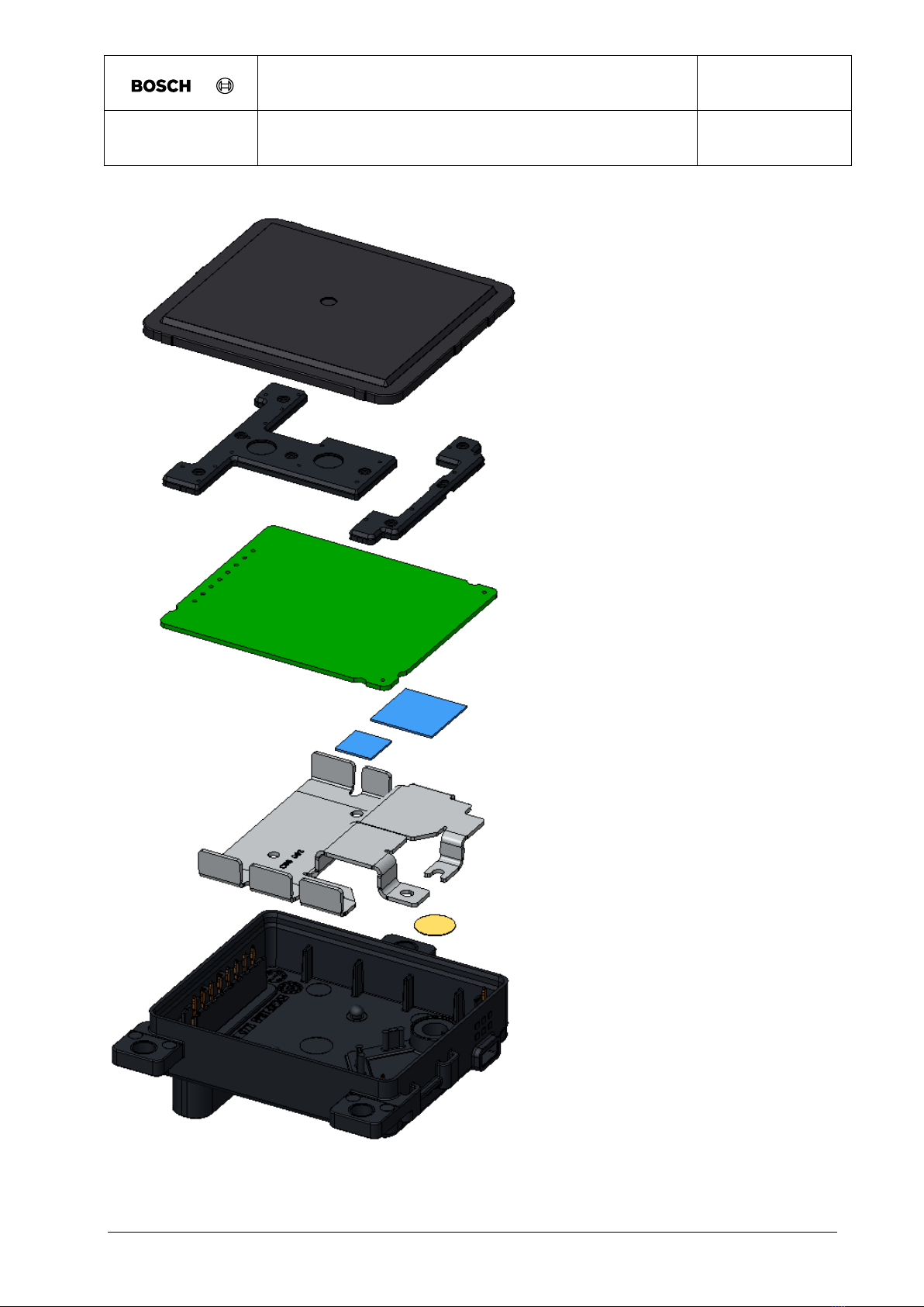
1.1.3. Preliminary Assembly concept .............................................................................. 5
1.2. Labeling of the product................................................................................................. 6
1.2.1. Radio Frequency Homologation ............................................................................ 6
1.2.1.1. Phrases and Markings.................................................................................... 6
1.3. Dimensions and weights .............................................................................................. 9
1.4. Power consumption / power output ............................................................................ 10
1.5. General remarks for service, repair and maintenance ................................................ 10
1.6. Information on disposal and recycling ........................................................................ 10
2. System description ............................................................................................................ 11
2.1. Vehicle integration interfaces ..................................................................................... 11
2.1.1.1. Radar Cone.................................................................................................. 11
2.1.1.2. Fascia design guidelines .............................................................................. 13
2.1.1.3. Installation Hints........................................................................................... 15
3. Technical data with measured variables and measuring conditions................................... 19
3.1. Mechanical characteristics ......................................................................................... 19
3.2. Electrical characteristics............................................................................................. 20
3.2.1. Electrical Vehicle Connector Pinning................................................................... 21
3.2.1.1. Pin Properties .............................................................................................. 21
3.2.1.2. Pin Assignment ............................................................................................ 21
3.2.2. Vehicle Power Supply ......................................................................................... 22
3.2.2.1. Constraints and Definitions .......................................................................... 22
3.2.2.2. Power Supply System 12V........................................................................... 22

Installation and Manual Documentation
Document date:
CC-DA/ESR1
FR5CPCCF
08 Aug 2019
Page:
3
© All rights reserved, Robert Bosch GmbH, also for the case of protected rights applications every power of disposal, like copy-right
and passing on rights, with us. The valid issue of this template is filed in CC-DA process landscape.
1. General product description
The present technical customer documentation describes FR5CPCCF, for which the Robert
Bosch GmbH has the assigned responsibility. In addition, it contains noncommittal descriptions
of components and functionalities, which are not in the responsibility of Robert Bosch GmbH,
but nonetheless determine or influence the behavior and performance of the particular vehicle
type series.
1.1. Main functions and properties of the product
1.1.1. Principle
The FR5CP radar sensor and control unit (SCU) contains a FMCW radar transceiver operating
in the globally harmonized frequency range of 76.0 - 77.0 GHz. It senses targets by emitting
many short frequency modulated waves using the transmit antennas while receiving waves
reflected by targets using the receive antennas. Distance and relative speed are determined via
beat frequency (due to travelling time of the waves) and phase differences between ramps (due
to change of distance in short time). By using the antenna diagram the angles of departure and
arrival of the radar waves can be determined.
Using the Bosch chirp sequence radar modulation, the FR5CP allows unambiguous
determination of relative speed in a single measurement cycle. Therefore, no complex object
models are needed for ambiguity resolution.
The radar reflections (strength, distance and relative speed, angular direction, and derived
values) are basis for building a comprehensive model of the sensed environment.

Installation and Manual Documentation
Document date:
CC-DA/ESR1
FR5CPCCF
08 Aug 2019
Page:
4
© All rights reserved, Robert Bosch GmbH, also for the case of protected rights applications every power of disposal, like copy-right
and passing on rights, with us. The valid issue of this template is filed in CC-DA process landscape.
1.1.2. Block diagram
Figure: Block diagram
The FR5CPCCF sensor is build on a single printed circuit board with integrated components:
•Microcontroller (M-Device) with multi-core architecture and dedicated radar signal
processing unit (SPU), Flash and RAM memory, peripheral units, CAN transceiver, as well as
safety features
•Radar Frontend MMIC in SiGe technology for frequency generation (VCO, PLL and
sequencer), power amplifiers (PA) and receiver including mixer, analog frontend processing,
ADC and digital frontend processing with digital baseband interface to the microcontroller as
well as clock generation and safety features
•Planar antenna array with three transmit antennas and four receive antennas
•A System-ASIC with power supply for internal voltages (except microcontroller core
power supply), a safety controller (SCON) with watchdog functionality and CAN-transceiver
•FlexRay PHY (transceiver)

Installation and Manual Documentation
Document date:
CC-DA/ESR1
FR5CPCCF
08 Aug 2019
Page:
5
© All rights reserved, Robert Bosch GmbH, also for the case of protected rights applications every power of disposal, like copy-right
and passing on rights, with us. The valid issue of this template is filed in CC-DA process landscape.
1.1.3. Preliminary Assembly concept
Figure: Assembly concept

Installation and Manual Documentation
Document date:
CC-DA/ESR1
FR5CPCCF
08 Aug 2019
Page:
6
© All rights reserved, Robert Bosch GmbH, also for the case of protected rights applications every power of disposal, like copy-right
and passing on rights, with us. The valid issue of this template is filed in CC-DA process landscape.
With only 3 main components (radome, PCB, lower housing), the assembly of the FR5CP SCU
is quite simple and is focusing to robust and cost effective mass production.
1.2. Labeling of the product
The radar devices provides information about:
- part-number
- series-number
- hardware and software version
- barcode information
- production date
- radar emission release information
- customer information
1.2.1. Radio Frequency Homologation
1.2.1.1. Phrases and Markings
The following phrases and markings are part of the radio frequency homologation and have to
be reproduced in the vehicle user manual.
1.2.1.1.1. Australia
1.2.1.1.2. Qatar
1.2.1.1.3. South Africa
1.2.1.1.4. Singapore
1.2.1.1.5. Ukraine
1.2.1.1.6. Serbia
1.2.1.1.7. Moldova
1.2.1.1.8. Mexico
1.2.1.1.9. Phillipines
1.2.1.1.10. Indonesia
1.2.1.1.11. Brunei Daressalam
1.2.1.1.12. Jordania

Installation and Manual Documentation
Document date:
CC-DA/ESR1
FR5CPCCF
08 Aug 2019
Page:
7
© All rights reserved, Robert Bosch GmbH, also for the case of protected rights applications every power of disposal, like copy-right
and passing on rights, with us. The valid issue of this template is filed in CC-DA process landscape.
1.2.1.1.13. United Arabic Emirates
1.2.1.1.14. Morocco
1.2.1.1.15. Malaysia
1.2.1.1.16. South Korea
1.2.1.1.17. Brazil
1.2.1.1.18. Taiwan
1.2.1.1.19. China
1.2.1.1.20. Hong Kong
1.2.1.1.21. Japan
1.2.1.1.22. Europe
1.2.1.1.23. USA
Once FCC approval is granted for FR5CPCCF, the following FCC ID has to be included in the
vehicle user manual and labelled on the product.
FCC ID: NF3-FR5CPCCF
The following warning text for RF equipment has to be included in the vehicle user manual:
User Manual statement according to §15.19
This device complies with Part 15 of the FCC Rules. Operation is subject to the following two
conditions:
1. this device may not cause harmful interference, and
2. this device must accept any interference received, including interference that
3. may cause undesired operation.
User Manual statement according to §15.21:
Changes or modifications made to this equipment not expressly approved by Robert BOSCH
GmbH may void the FCC authorization to operate this equipment.
User Manual statement according to §15.105:
This equipment has been tested and found to comply with the limits for a Class A digital device,
pursuant to Part 15 of the FCC Rules. These limits are designed to provide reasonable
protection against harmful interference when the equipment is operated in a commercial
environment. This equipment generates, uses, and can radiate radio frequency energy and, if

Installation and Manual Documentation
Document date:
CC-DA/ESR1
FR5CPCCF
08 Aug 2019
Page:
8
© All rights reserved, Robert Bosch GmbH, also for the case of protected rights applications every power of disposal, like copy-right
and passing on rights, with us. The valid issue of this template is filed in CC-DA process landscape.
not installed and used in accordance with the instruction manual, may cause harmful
interference to radio communications. Operation of this equipment in a residential area is likely
to cause harmful interference in which case the user will be required to correct the interference
at his own expense.
RF Exposure Information according 2.1091 / 2.1093 / KDB 447498 / OET bulletin 65:
Radio frequency radiation exposure Information:
This equipment complies with FCC radiation exposure limits set forth for an uncontrolled
environment. This equipment should be installed and operated with minimum distance of 20 cm
between the radiator and your body. This transmitter must not be co-located or operating in
conjunction with any other antenna or transmitter.
1.2.1.1.24. Canada
Once Canada approval is granted for FR5CPCCF the following ISED certification number,
PMN and HVIN has to be included in the vehicle user manual and labelled on the product
on the product.
IC: 3887A-FR5CPCCF
HVIN: FR5CPCCF
PMN: Front Radar 5 Car Plus CAN CAN Flexray
The following warning text for RF equipment has to be included in the vehicle user
manual:
RF equipment according to RSS_GEN in English and French language
This device complies with Industry Canada license-exempt RSS standard(s). Operation is
subject to the following two conditions: (1) this device must not cause interference, and (2) this
device must accept any interference, including interference that may cause undesired operation
of the device.
Le présent appareil est conforme aux CNR d'Industrie Canada applicables aux appareils radio
exempts de licence. L'exploitation est autorisée aux deux conditions suivantes: (1) l'appareil ne
doit pas produire de brouillage, et (2) l'utilisateur de l'appareil doit accepter tout brouillage
radioélectrique subi, même si le brouillage est susceptible d'en compromettre le
fonctionnement.

Installation and Manual Documentation
Document date:
CC-DA/ESR1
FR5CPCCF
08 Aug 2019
Page:
9
© All rights reserved, Robert Bosch GmbH, also for the case of protected rights applications every power of disposal, like copy-right
and passing on rights, with us. The valid issue of this template is filed in CC-DA process landscape.
RF Exposure Information according to RSS-102 in English and French language:
This equipment complies with FCC and IC radiation exposure limits set forth for an uncontrolled
environment. This equipment should be installed and operated with minimum distance of 20 cm
between the radiator and your body. This transmitter must not be co-located or operating in
conjunction with any other antenna or transmitter.
Cet équipement est conforme aux limites d'exposition aux rayonnements IC établies pour un
environnement non contrôlé. Cet équipement doit être installé et utilisé avec un minimum de 20
cm de distance entre la source de rayonnement et votre corps. Ce transmetteur ne doit pas etre
place au meme endroit ou utilise simultanement avec un autre transmetteur ou antenne.
1.2.1.1.25. Argentina
1.3. Dimensions and weights
Outside dimension:
Box volume, total Length (depth in X-direction) = 18.7 mm
Detailed dimensions see offer drawing.
Outside dimension:
Box volume, total Width = 62.6mm
Detailed dimensions see offer drawing.
Outside dimension:
Box volume, total Height = 72mm
Detailed dimensions see offer drawing.
Maximum weight of complete SCU (w/o heating) w/o mounting device and poka yoke element
>80gr.

Installation and Manual Documentation
Document date:
CC-DA/ESR1
FR5CPCCF
08 Aug 2019
Page:
10
© All rights reserved, Robert Bosch GmbH, also for the case of protected rights applications every power of disposal, like copy-right
and passing on rights, with us. The valid issue of this template is filed in CC-DA process landscape.
1.4. Power consumption / power output
This section describes the power consumption of the SCU for different operating states.
Symbol Parameter
Note or Test Condition
min typ max Unit
P_RF_on operating power consumption
- RF on, approx. 30%
duty cycle
- COM Interfaces ON
- Processing Unit: M
- VBATT=14V +/- 5%
- 4 W
Symbol Parameter
Note or Test Condition
min typ max Unit
P_RF_off operating power consumption
- RF off
- COM Interfaces ON
- Processing Unit: M
- VBATT=14V +/- 5%
- 2,5 W
1.5. General remarks for service, repair and maintenance
Repair and maintenance of the product is not allowed
Sensor can`t be opened without damaging.
In case of service the Sensor needs to be replaced.
1.6. Information on disposal and recycling
All Materials are released regarding the following regulations:
- ELV (Altautorichtlinie) and GADSL (BBM)
- RoHS
- REACh

Installation and Manual Documentation
Document date:
CC-DA/ESR1
FR5CPCCF
08 Aug 2019
Page:
11
© All rights reserved, Robert Bosch GmbH, also for the case of protected rights applications every power of disposal, like copy-right
and passing on rights, with us. The valid issue of this template is filed in CC-DA process landscape.
2. System description
2.1. Vehicle integration interfaces
This chapter describes the requirements for all parts mounted in front or around the sensor, like
painted bumper, unpainted cover and emblem/radome, regarding RF integration at 77 GHz with
FR5plus radar sensors.
Values are marked with t.b.c. or t.b.d. showing that they have to be confirmed or defined during
the development process.
As product development is an on-going process, we reserve the right to make amendments in
line with technical progress.
The radar sensor performance should be influenced as low as possible by the installation
behind a fascia. Therefore the two-way radar loss by the fascia should be as low as possible
and the reflection attenuation must fulfill the requirements listed below.
Vertical misalignment will cause additional attenuation reducing the maximum range.
Horizontal misalignment will cause reduced detection at higher azimuth angles.
Ghost target detection caused by interference signals of multiple reflection at fascia and metallic
parts of the vehicle must be avoided. A simulation can be offered to evaluate the risk and the
need of using absorber material to suppress this unwanted signal. Because the threshold of
detection is very low, a high attenuation is required. Plastic material can only achieve high
enough attenuation, if carbon black is added.
2.1.1.1. Radar Cone
Radar Cone for PLUS Family
The radar cone describes the zone where the fascia has to be optimized. Any parts of the
vehicle inside the radar cone may influence the radar performance. Cables, brackets, bars etc.
should not touch the radar cone. The fascia in this zone may not have bends and edges as well
as changes in thickness or material or painting.
Based on the footprint on the top side of the radar PCB the cone is characterized by a vertical
and a horizontal opening angle. The footprint is centered regarding to the sensor housing. A
CAD model of the radar cone is available.
The footprint for radar cone has the following dimensions: (W x H) 55 mm x 55 mm

Installation and Manual Documentation
Document date:
CC-DA/ESR1
FR5CPCCF
08 Aug 2019
Page:
12
© All rights reserved, Robert Bosch GmbH, also for the case of protected rights applications every power of disposal, like copy-right
and passing on rights, with us. The valid issue of this template is filed in CC-DA process landscape.
Figure: Footprint of the radar cone. For better visibility the footprint is shown on top of the
sensor housing.
Radar cone definition for covered installation (FR5CP):
The horizontal opening angle depends on the angle range that is evaluated by the sensor in
azimuth and elevation, whereby the opening angle of the radar cone has to be larger than the
angle range that is evaluated. For covered integration the radar cone is 10° larger than the used
angle range that is evaluated by the sensor.
Radar cone:
±70° (1) in horizontal direction (not including misalignment)
± 20° in vertical direction (not including misalignment)
(1) Valid for angle measurement range of ±60°

Installation and Manual Documentation
Document date:
CC-DA/ESR1
FR5CPCCF
08 Aug 2019
Page:
13
© All rights reserved, Robert Bosch GmbH, also for the case of protected rights applications every power of disposal, like copy-right
and passing on rights, with us. The valid issue of this template is filed in CC-DA process landscape.
2.1.1.2. Fascia design guidelines
Material
Material with low dielectric constant (r) and low dielectric loss factor tanδat 77 GHz should be
used. Recommended are materials based on polypropylene (PP) and polymethyl methacrylate
(PMMA), while materials like polycarbonate (PC) and acrylonitrile butadiene styrene (ABS) are
still ok. The material shall be homogenous, compounds including glass fiber, carbon fiber or
metal particles are not recommended.
The fascia shall be designed for radar transparency. The thickness shall be a multiple of the half
wavelength (in the material) to minimize the influence of the fascia. The quality criteria of radar
transparency is the reflection coefficient of the radome/fascia. Tolerances of the overall
thickness and the dielectric constant of the used material influence the amount of reflection at
the radome/fascia. Additional influence occurs due to curvature of the fascia. Therefore the
radius has to be as large as possible. With sharp edges the negative influence will increase
significantly. Not allowed are ribs, structures and steps changing the thickness of the
radome/fascia.
Painting
The layer structure of the painting, typically made of three painting layers consisting of primer,
base coating and clear coating, will increase the effective permittivity value r,eff and dielectric
loss factor tanδof the painted plate used as fascia.
Fascia Classification (FR5CP)
The two-way radar loss caused by fascia should be as low as possible. High losses decrease
the sensor performance regarding range and angle estimation. Therefore it is recommended to
achieve a two-way radar loss below 3 dB.

Installation and Manual Documentation
Document date:
CC-DA/ESR1
FR5CPCCF
08 Aug 2019
Page:
14
© All rights reserved, Robert Bosch GmbH, also for the case of protected rights applications every power of disposal, like copy-right
and passing on rights, with us. The valid issue of this template is filed in CC-DA process landscape.
Classification of reflection caused by the fascia
1. Reflection coefficient <-15 dB
is achieved when fascia has optimized thickness within a tolerance of ±0.1 mm and permittivity
within a tolerance of ±0.02. Dielectric loss factor tanδ shall be <0.01. With such low reflection a
vertical tilt angle of 0° is possible. This is the case for unpainted or a single e.g. black paint cover.
Also well designed emblems without air gap inside may be usable.
2. Reflection coefficient <-10 dB
is achieved when fascia has optimized thickness within a tolerance of ±0.2 mm and permittivity
within a tolerance ±0.02. Dielectric loss factor tanδ shall be <0.03. With such reflection a vertical tilt
angle of 0° must be avoided.
3. Reflection coefficient <-6 dB
is achieved when fascia has optimized thickness within a tolerance of ±0.2 mm and permittivity
within a tolerance of ±0.2. Dielectric loss factor tanδ shall be <0.05. With such reflection a vertical
tilt angle of >18° is required. This is the case for painted bumper especially when various colors are
used.
4. Reflection coefficient >-6 dB
is achieved when fascia has no optimized thickness or a painting with high metallic content is used.
The attenuation will exceed the maximum allowed limit.
The examples described in the classification of reflection are derived from evaluation of flat
plates with constant thickness and homogeneous material. Deviations from this situation may
cause a change in classification and the vertical tilt angle of fascia has to be increased.
Surface Properties of the fascia
The surfaces of the fascia shall not exceed an average roughness height of 20 µm
(corresponding to ISO 1302 class N10; VDI 3400 class 45).

Installation and Manual Documentation
Document date:
CC-DA/ESR1
FR5CPCCF
08 Aug 2019
Page:
15
© All rights reserved, Robert Bosch GmbH, also for the case of protected rights applications every power of disposal, like copy-right
and passing on rights, with us. The valid issue of this template is filed in CC-DA process landscape.
2.1.1.3. Installation Hints
To enable the full performance of the radar sensor, it is recommended to use the following
installation hints and guidelines for the RF integration of the sensor.
Sensor rotation around radome normal (FR5CP)
The sensor shall not be rotated more than 1.5° around the normal of the radome surface.
Maximum angle between radar cone and fascia
The angle αbetween the radar beam inside the radar cone and the fascia may not be larger
than 70° anywhere inside the radar cone.
Figure: Maximum angle between fascia and radar cone

Installation and Manual Documentation
Document date:
CC-DA/ESR1
FR5CPCCF
08 Aug 2019
Page:
16
© All rights reserved, Robert Bosch GmbH, also for the case of protected rights applications every power of disposal, like copy-right
and passing on rights, with us. The valid issue of this template is filed in CC-DA process landscape.
Minimum distance between sensor and fascia
The minimum distance between the sensor radome and the fascia or any other part of the
vehicle may not be smaller than 5 mm.
This is valid for fascia parts fulfilling the following requirements.
Figure: Minimum distance above sensor radome
Vertical tilt of fascia (FR5CP)
The vertical tilt angle between the sensor normal and the surface normal of the fascia shall be in
the range according to the following table.
Figure: vertical tilt angle of fascia to sensor normal

Installation and Manual Documentation
Document date:
CC-DA/ESR1
FR5CPCCF
08 Aug 2019
Page:
17
© All rights reserved, Robert Bosch GmbH, also for the case of protected rights applications every power of disposal, like copy-right
and passing on rights, with us. The valid issue of this template is filed in CC-DA process landscape.
Minimum
vertical tilt
reflection
coefficient
max. tolerance
thickness
tolerance εrtanδ application
<-15 dB ±0.1 mm ±0.02 <0.01
unpainted,
(black)
painting,
embleme
±0.2 mm ±0.02 <0.03
unpainted,
(black)
painting,
embleme
±0.1 mm ±0.2 <0.03
painted
bumper
>18° <-6 dB ±0.2 mm ±0.2 <0.05
painted
bumper
>8°
<-10 dB
Table: minimum vertical tilt angle of fascia to sensor normal
Curvature of fascia for FR5CP
Curvature of the fascia may influence the radar performance, especially with low vertical tilt
angles. The minimum radius of the curvature shall be according to the following rules:
R > 350 mm, no significant influence expected
R < 350 mm, significant influence possible, has to be evaluated
R < 200 mm, significant influence expected, not recommended
Absorber around the sensor
It is highly recommended to use a cone made of absorber material around the radar cone of the
sensor to prevent ghost targets. The design of the absorber cone must fulfill the following
design guidelines (reflection from outside the radar cone, multipath reflection).
Reflection from outside the radar cone
Reflections from structures located outside the radar cone have to be avoided.
Furthermore interference signals picked up by the sensor antennas should be avoided by
keeping a minimum distance (d) of 5 mm to 10 mm for parts in front of the sensor.
Even with compliance to the radar cone, reflections at parts outside the radar cone may disturb
the received signal. Reflections at parts causing an interference signal to the receiving antenna
and reflections at parts getting to the receiving antenna after a second reflection at the fascia
(multipath reflection).

Installation and Manual Documentation
Document date:
CC-DA/ESR1
FR5CPCCF
08 Aug 2019
Page:
18
© All rights reserved, Robert Bosch GmbH, also for the case of protected rights applications every power of disposal, like copy-right
and passing on rights, with us. The valid issue of this template is filed in CC-DA process landscape.
Closed surfaces of brackets and masks made of metal or high reflecting material need a tilt
angle being arranged that the reflection is not received by the receiving antennas of the sensor.
Figure: Reflection at bracket or mask
For closed surfaces (masks) in azimuth, the angle between mask surface and the normal
vector n of the sensor shall be above 75° for parts outside of the radar cone.
For closed surfaces (masks) in elevation, the angle between mask surface and the normal
vector n of the sensor shall be above 20° for parts outside of the radar cone.
Multipath reflection
Reflections of incoming signals at bracket or shielding absorber are coming back to the sensor if
reflection at the bumper occurs. The figure below shows the situation which should be avoided.
The worst case happens if the combination of the vertical tilt angles of shielding and bumper is
1= 2/ 2 . For a low interference signal the condition shall be:
1> 2/ 2 +10°
or
1< 2/ 2 -10°

Installation and Manual Documentation
Document date:
CC-DA/ESR1
FR5CPCCF
08 Aug 2019
Page:
19
© All rights reserved, Robert Bosch GmbH, also for the case of protected rights applications every power of disposal, like copy-right
and passing on rights, with us. The valid issue of this template is filed in CC-DA process landscape.
Figure: a) Requirements for parts outside radar cone to avoid multipath reflection
The same requirements are valid for a horizontal tilt of the fascia.
3. Technical data with measured variables and measuring conditions
3.1. Mechanical characteristics
Gravel bombardment:
According to ISO 20567-1 against back housing (covered installation)
Mechanical shock:
According to DIN EN 60068-2-27
500m/s^2 / 6ms duration
Mechanical vibration (broadband random vibration):
According to DIN EN 60068-2-64
Frequency spectrum 5 Hz - 2000 Hz according to the following profile

Installation and Manual Documentation
Document date:
CC-DA/ESR1
FR5CPCCF
08 Aug 2019
Page:
20
© All rights reserved, Robert Bosch GmbH, also for the case of protected rights applications every power of disposal, like copy-right
and passing on rights, with us. The valid issue of this template is filed in CC-DA process landscape.
aeff = 30.8 m/s²
Protection class:
According to International Protection Marking, ISO 20653
IP6Kx, IPx6K, IPx7, IPx9K
Temperature range with restricted operation (communication interface working):
Top_max=+85°C ... Tmax=+95°C.
Temperature range of operation:
Top_min= -40°C ... Top_max=+85°C.
Duration see Reliability
Temperature range of operation:
Top_min= -40°C ... Top_max=+85°C.
Duration see Reliability
Corrosion resistance against salt spray and humidity
According to DIN EN 60068-2-11
Sensor may not be exposed to direct UV light for more than 48h
3.2. Electrical characteristics
The chapter electrical car integration describes the vehicle connector interface of the Radar
SCU.
The detailed description of the following connection topics are adapted to the defined feature
configuration:
- Connector Pinning
Table of contents
Other Bosch Radar manuals
Popular Radar manuals by other brands

Radarsign
Radarsign TC-800 installation manual

Magnetrol
Magnetrol eclipse 705 Safety manual

Acconeer
Acconeer A111 datasheet

Endress+Hauser
Endress+Hauser Levelflex FMP51 Brief operating instructions

Continental Refrigerator
Continental Refrigerator RightViu Mounting instructions

Geoscanners AB
Geoscanners AB SVC-821 Assembly instruction

Data Signs
Data Signs VMS II Series Advanced features

Preco
Preco PreView WorkSight for Waste w/VL ZC Quick installation guide

Decatur Electronics
Decatur Electronics SVR DUAL user manual

AGD
AGD 343 product manual

GSSI
GSSI PaveScan RDM 2.0 manual

Endress+Hauser
Endress+Hauser Micropilot FMR67B operating instructions