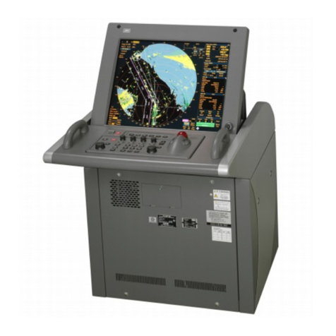
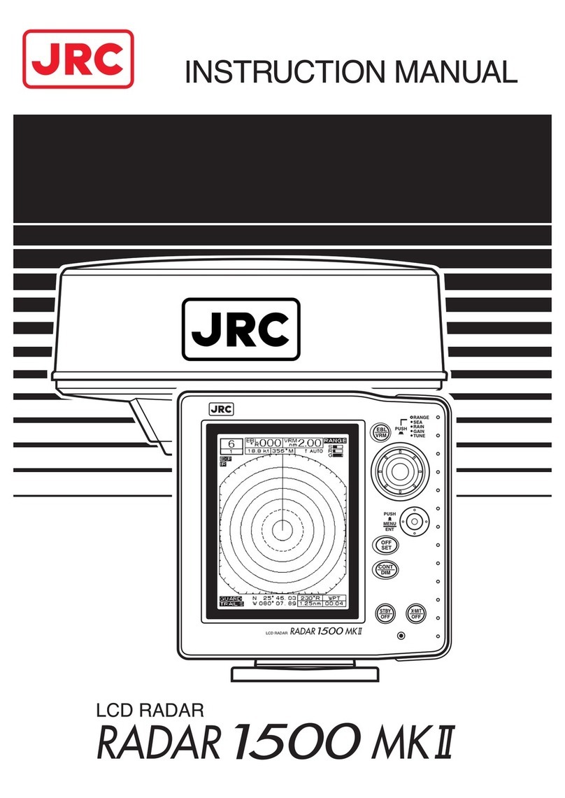
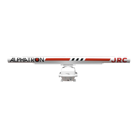
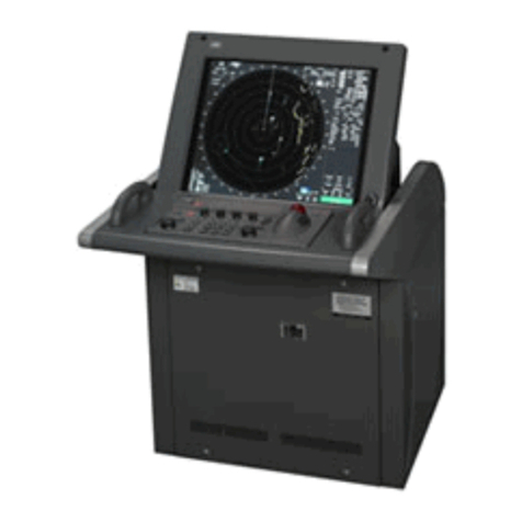
JRC Radar 3000 User manual


I
Thank you for purchasing the RADAR 3000 radar.
It will provide many years of trouble free use when operated prop
erly.
To use your RADAR 3000 properly, please observe the following precautions:
●Read this manual thoroughly to gain a good understanding of the capabili
ties and requirements of this equipment.
●
Store the manual in a safe location so that it does not become lost or damaged.
●Observe standard storage and handling procedures for electronic equipment.
●If after proper installation RADAR 3000 appears to be defective, please con
tact your JRC sales or service representative for assistance.
Symbols Used In This Manual
The following symbols are used in this instruction manual and on the product
itself to ensure correct handling of the product and to protect your safety. Their
meanings are explained below. Please take note of these symbols as you read
the manual.
This symbol is intended to alert the user to the presence of dangerous items to be
handled with every possible cation. For safe operation, read the instructions
carefully.
These symbols are intended to alert the user to the presence of prohibited items
that must never be performed. Read the instructions carefully and do not at
tempt things prohibited.
This symbol is intended to alert the user to the presence of instructions whose
performance is absolutely necessary. Read the instructions carefully and be
sure they are executed.
Electric shocks
Prohibition
Prohibits
disassembly
Instruction
A safety warning to alert you of possible physical harm to you
or the equipment.
Equipment damage precaution to alert you of possible harm
and/or failure of equipment.

II
Operating Precautions
To avoid electrical shock, never touch the inside of the scanner or
display unit. Leave protective cover on.
High voltage present inside of these units could cause personal injury.
Refer equipment servicing to authorized JRC personnel.
Avoid routinely entering the nearby vicinity of the scanner unit.
The scanner unit rotates quickly and could cause personal injury. The
scanner should be installed in a high place such as the cabin roof,
flying bridge, radar mast, or the top base frame of your ship. If the
scanner cannot be located out of normal human reach, it should be
surrounded with a fence. Prolonged human exposure to radar signals
at close range is not recommended.
Before approaching or removing the scanner unit, turn off the STBY/
OFF and X MIT/OFF keys on the display unit. Cable connector P1 on
the display unit should be disconnected before removing the scanner
unit from its installed position.
Never sit on the scanner unit.
The radome and/or the parts in the scanner unit may be damaged.
Use your RADAR 3000 system properly by following the instructions
in this manual.
Incorrect operation can detract from optimum system performance.
This radar unit is only an aid to navigation. Its accuracy can be af
fected by many factors including equipment failure or defects, envi
ronmental conditions, and improper handling or use. It is the user’s
responsibility to exercise common prudence and navigational judge
ment. This radar unit should not be relied upon as a substitute for such
prudence and judgment.
CAUTION
WARNING

III
SCANNER UNIT NKE-1046
DISPLAY UNIT NCD-3744
Equipment Photograph
III
SCANNER UNIT NKE-1046
DISPLAY UNIT NCD-3744
Equipment Photograph

IV
Table of Contents
Symbol Used In This Manual I
Operating Precautions II
Equipment Photograph III
Radar Glossary of Terms VI
SECTION 1 INTRODUCTION
1.1 FUNCTION 1
1.2 FEATURES 1
1.3 COMPONENTS 2
1.4 CONSTRUCTION 3
SECTION 2 OPERATING CONTROLS AND FUNCTIONS
2.1 CONTROL PANEL 5
SECTION 3 INSTALLATION
3.1 UNPACKING AND INSPECTION 7
3.2 PLANNING THE INSTALLATION 7
3.3 MOUNTING THE DISPLAY UNIT 9
3.4 MOUNTING THE SCANNER UNIT 11
3.5 CONNECTING THE SCANNER UNIT CABLE 11
3.6 ELECTRICAL CONNECTION 12
3.7 INITIAL OPERATION AND CHECK OUT 15
SECTION 4 OPERATION
4.1 LAYOUT OF CONTROLS 19
4.2 TURNING THE RADAR ON AND OFF 20
4.3 SELECTING A RANGE 22
4.4 ADJUSTING RECEIVER SENSITIVITY 22
4.5 ADJUSTING TUNING 22
4.6 REDUCING SEA CLUTTER 23
4.7 ADJUSTING RAIN CLUTTER 23
4.8 SETTING CRT BRILLIANCE 23
4.9 SETTING DIMMER 23
4.10 SETTING OFFSENT 24
4.11 RANGE MEASUREMENT 24
4.12 BEARING MEASUREMENT 25

V
4.13 SETTING GUARD 26
4.14 RINGS 27
4.15 SHM 27
4.16 POSITION 27
4.17 WAYPOINT 27
4.18 READ OUT DIMENSION OF BEARING 28
4.19 TRAIL 28
4.20 TARGETS EXPANSION 28
4.21 REDUCING INTERFERENCE REJECTION 28
4.22 MOB (Man Over Board) 28
4.23 TIMED TX MODE 29
4.24 SETTING AUTO/MANUAL TUNING 29
4.25 IN CASE AN UNUSUAL CONDITION DCCURS
DURING OPERATION 29
4.26 LANGUAGE 29
4.27 OPERATING MENU 30
4.28 DISPLAY OF RADAR TRANSPONDER 37
SECTION 5 MAINTENANCE
5.1 PREVENTIVE MAINTENANCE 38
5.2 CLEANING THE SCANNER UNIT 39
5.3 CLEANING THE DISPLAY SCREEN 39
SECTION 6 AFTER SALES SERVICE
40
SECTION 7 DISPOSAL
7.1 EQUIPMENT DISPOSAL 42
7.2 DISPOSAL OF USED BATTERY 42
7.3 DISPOSAL OF USED MAGNETRON 42
SECTION 8 SPECIFICATIONS
8.1 GENERAL 43
8.2 SCANNER UNIT 44
8.3 DISPLAY UNIT 44
APPENDIX
Fig. 1
RADAR 3000 SCANNER UNIT (NKE 1046) RADOME TEMPLATE

VI
Radar Glossary of Terms
The following is a list of abbreviations and acronyms which may be used in
the text of the manual.
A/D Analog to Digital conversion
ALM Alarm In, also known as the approach alarm. For targets set zone.
approaching a preset zone.
CPU Central Processing Unit
EBL Electronic Bearing Line
EXP Expansion
FTC
Fast Time Constant, also known as rain and snow clutter suppression
GPS Global Positioning System
IR Interference Rejection
KM Kilometer
LL Latitude/Longitude
MH Modulator High voltage
NM Nautical Mile
PCB Printed Circuit Board
PPI Plan Position Indicator
PW Pulse Width
RR Range Rings (fixed)
SHM Ship’s Heading Marker
STBY Standby
STC
Sensitivity Time Constant, also known as sea surface clutter suppression
TD Time Difference
TI Trigger
VD Video
VOM Volt Ohm Meter
VRM Variable Range Marker
WPT Waypoint
X MIT Transmit

1
SECTION 1
1.1 FUNCTION
The JRC RADAR 3000 Radar is compact raster scan radar with a 4 kW trans
mitter and a 7 inch cathode ray tube. Except for special tubes, they are all made
up of solid state device for improved reliability.
1.2 FEATURES
●Improved anti sea clutter and anti rain clutter suppression
●Easy control for VRM, EBL, GAIN, anti sea, and anti rain, using J DIAL
●Approach and departure guard zone with audible alarm
●Use of robust material, aluminum die cast
●Easy to understanding other target information for range, bearing and Lat/
Long by using cursor
●Destination mark can be displayed
●2/3 radius off centering for any direction
●Trail indication
●Man overboard indication
●Intermittent transmission
INTRODUCTION
INTRODUCTION

2
1.3 COMPONENTS
Table 1 1 indicates a listing of items that are included with your new radar
system.
INTRODUCTION
Table 1-1 EQUIPMENT SUPPLIED
Description Model No. or Code No.
Remarks
Radar 3000 system JMA 1541
Scanner Unit NKE 1046
Display Unit NCD 3744
Sun Shield MTV301854A
Interunit Cable CFQ8026 10
12 cores composite cables
(10 m)
Power Cable CFQ 2646 (2 m)
Instruction Manual 7ZPRD0414A
This Manual
Standard Spares 6ZXRD00192
8 A Fuse × 2
4 A Fuse × 3
6 Pin connector 5JWHZ00065
For data communication
with NMEA
Sun Cover MTV301855
Scanner Mounting Hardware MPXP31711
Display Mounting Hardware MPTG02024

3
FIG. 1-2 SCANNER MOUNTING DIMENSION
FIG. 1-1 DISPLAY MOUNTING DIMENSIONS
1.4 CONSTRUCTION
INTRODUCTION
3
FIG. 1-2 SCANNER MOUNTING DIMENSION
FIG. 1-1 DISPLAY MOUNTING DIMENSIONS
1.4 CONSTRUCTION
INTRODUCTION

4 OPERATING CONTROLS AND FUNCTIONS
SECTION 2
OPERATING CONTROLS AND FUNCTIONS
FIG. 2-1 OPERATING CONTROLS
SEA
J DIAL
VRM/EBL Key
JOYSTICK
Range Up/Down Key
GUARD Key
EXP Key
OFFCENT Key
SHM/RINGS Key
Brilliance/Dimmer Key
MOB Key
Transmit/off Key
Stand by/off Key
DISPLAY UNIT
4 OPERATING CONTROLS AND FUNCTIONS
SECTION 2
OPERATING CONTROLS AND FUNCTIONS
FIG. 2-1 OPERATING CONTROLS
SEA
J DIAL
VRM/EBL Key
JOYSTICK
Range Up/Down Key
GUARD Key
EXP Key
OFFCENT Key
SHM/RINGS Key
Brilliance/Dimmer Key
MOB Key
Transmit/off Key
Stand by/off Key
DISPLAY UNIT

5
2.1 CONTROL PANEL
①Stand by/off Key
・Turn ON power to Display and Scanner and activates 90 second countdown
timer.
・Press STBY/OFF key to Stand by mode while in the Transmitting mode.
・Press STBY/OFF and X MIT/OFF keys simultaneously to shut off.
②Transmit/off Key
・Turn ON transmitter which activates Radome.
・Press STBY/OFF and X MIT/OFF keys simultaneously to shut off.
③J DIAL
・Push to select SEA, RAIN, GAIN and TUNE for control.
SEA reduces sea returns.
RAIN reduces rain or snow returns.
GAIN controls strength of target returns.
TUNE manually fine tunes receiver by peaking tuning bar (No tuning
bar in AUTO tune).
・Control the SEA, RAIN, GAIN, TUNE, VRM, EBL, Contrast for desire
setting.
④VRM/EBL key
・Enable a VRM or EBL for display. A short press to turn on or off selected
VRM or EBL. Press and hold, selects VRM or EBL for control by using J
DIAL.
⑤JOYSTICK
・Position cursor setting.
・Enables MENU for setups and selection.
⑥GUARD Key
・Enables or disables Guard Zone alarm as set with the JOYSTICK and I or O
operation.
I=InmodealarmO=OutmodealarmBlank=OFF
OPERATING CONTROLS AND FUNCTIONS

6
⑦EXP Key
・Target Expander ON/OFF.
⑧OFFSET Key
・Places origin at any point on screen up to 2/3 radius. Inop on 24 nm range.
⑨SHM/RINGS Key
・Enables or disables the fixed range rings alternately.
・Momentarily disables the Heading Flash while key is held depressed.
⑩Brilliance/Dimmer Key
・Brilliance level for video, characters, rings and EBL.
・Setting panel illumination.
⑪MOB Key
・Marks the point where the incident occurred.
⑫Range Up/Down key
・Increases or decreases the range scale in use.
OPERATING CONTROLS AND FUNCTIONS

7
SECTION 3
This section provides practical guidelines to assist in the planning and installa
tion of the RADAR 3000 aboard your vessel.
3.1 UNPACKING AND INSPECTION
Use care when unpacking the RADAR 3000 radar from the shipping carton to
prevent damage to the contents. It is also good practice to save the carton and
the interior packing material until the radar has been satisfactorily installed on
the vessel. The original packing material should be used in the unlikely event
that it is necessary to return the unit for service.
3.2 PLANNING THE INSTALLATION
The layout for installing the RADAR 3000 should be planned to give the best
operation and service aboard your particular vessel. In general, the scanner unit
should be mounted as high as possible above the waterline. The display unit
should be installed in a convenient viewing position near the helm. Keep in
mind the optimum viewing angle when installing the display. You may want to
apply power in advance of installing the unit as that you can determine a satis
factory viewing angle.
A 10 meter length of interunit cable is furnished for interconnecting the two
main units (scanner and display). This length of interunit cable should be suffi
cient to complete the cable run required on most small vessels. It is recom
mended that the maximum length of interunit cable not exceed 20 meters.
A general system diagram for the RADAR 3000 is shown on the following
page.
INSTALLATION
INSTALLATION

8 INSTALLATION
FIG. 3-1 GENERAL SYSTEM DIAGRAM
8 INSTALLATION
FIG. 3-1 GENERAL SYSTEM DIAGRAM

9
3.3 MOUNTING THE DISPLAY UNIT
When planning the installation for your display unit, the following conditions
should be considered to ensure dependable and trouble free operation.
1) The mounting location should be easily accessible to allow operation of the
front panel controls.
2) There should be adequate ventilation.
3) There should be sufficient space behind the display unit to allow cable con
nections to the rear panel connectors.
4) The display unit should be located near a DC power source.
5) The selected location should be far enough away from device that may cause
interference, such as motors and generators.
6) Generally, the display unit should be located in a protected area away from
prolonged direct exposure to rain and salt spray. It is good practice to pro
tect your valuable electronic equipment as much as possible.
The display unit can be conveniently mounted on a chart table, or bulkhead
mounted in a desired location. Using the outline of FIG 3 1 and 3 2 as a guide,
install the display unit and secure to the mounting surface.
INSTALLATION

10
FIG. 3-3 SCANNER MOUNTING DIMENSION
INSTALLATION
FIG. 3-2 DISPLAY MOUNTING DIMENSIONS
10
FIG. 3-3 SCANNER MOUNTING DIMENSION
INSTALLATION
FIG. 3-2 DISPLAY MOUNTING DIMENSIONS

11
3.4 MOUNTING THE SCANNER UNIT
Selecting an adequate location for the scanner unit requires careful consider
ation. On many small vessels, the unit can be installed on a mast platform, on
an arch, or on a bridge structure near the ship’s centerline.
The radiator beam should not be obstructed by nearby large objects. Locate the
unit where large structures such as superstructures, searchlight, horns or masts
are not in the same horizontal plane, otherwise, blind areas and false targets can
appear on the radar screen.
Using the outline drawing of FIG 3 3 or template in the front of the manual as
a guide, install the scanner unit and secure it to a solid mounting surface.
Usually the mounting surface for the scanner unit should be parallel with the
ship’s waterline. Some vessels, however, may adopt a higher bow angle when
the vessel is at its cruising speed. This substantially alters and raises the radar’s
radiation plain. In this case nearby target detection might be poor. It may be
helpful to lower the radar beam towards the parallel by shimming the radar
pedestal so as to tilt the beam angle slightly downward with respect to the wa
terline.
3.5 CONNECTING THE SCANNER UNIT CABLE
①Route the scanner unit cable from bottom of the mounting base and connect
them to connectors J1 and W1 of the CME 229 modulator printed circuit
board.
②Tighten the ground terminal and securing the clamping plate with the rub
ber grommet.
INSTALLATION

12
CAUTION
INSTALLATION
3.6 ELECTRICAL CONNECTION
3.6.1 DC POWER CABLE
The RADAR 3000 will work with any ship’s mains within the 10.2 to 42 V
range, since it contains a power regulator circuit. Connect the power cable to a
DC source. The power cable normally should be wired through the circuit breaker.
The white lead wire of the power cable should be connected to the positive
source terminal and the black lead to negative source terminal. The shielded
wire should be connected to the ship’s RF ground. Should the power connec
tions be inadvertently reversed, a protective fuse will blow. Recheck the input
power leads for correct polarity with a VOM and reconnect the leads observing
correct polarity. Replace the fuse.
3.6.2 EXTERNAL SYSTEM INTERFACE
FIG. 3-4 SCANNER UNIT CABLE CONNECTION PROCEDURE
Ground Terminal
Clamping Plate
Rubber Grommet
Interconnecting Cable
Cable Clamp
TO CME 229
J1
P1
W1
PW1
To connect with NAV-AID and/or compass, make sure pin as-
si nment, if used same connector.
In case of different pin assi nment, the RADAR 3000 or con-
nected NAV-AID will be dama ed.

13INSTALLATION
The RADAR 3000 will interface with any NAV AID (GPS or LORAN) and
compass that has the standard NMEA0182 or NMEA0183 output. The inputs
from NAV AID will be digital data conforming to the NMEA0183 formats to
drive various radar features such as waypoint mode. If more than one data type
is present at the radar inputs (for example; compass and NAV AID), a system
priority has been established in the radar’s software to respond to the inputs in
driving the features. The assigned priorities are set in this manner:
HEADING: 1. Compass (NMEA0183 “HSC,HDM,HDT,VHW”)
2. NAV AID (NMEA0183 “RMC,RMA,VTG”)
POSISION: 1. NAV AID (NMEA0183 “RMC,RMA,GLL,GTD”)
SPEED: 1. NAV AID (NMEA0183 “RMC,RMA,VTG”)
2. Compass (NMEA0183 “VHW”)
WAYPOINT: 1. NAV AID (NMEA0183 “RMB,BWC”)
Using the outline of FIG 3 5 as a guide, connect the RADAR 3000 to your
NAV AID and compass.
①NAV (Data Output) NAV AID
②NAV (Data Ground) NAV AID
③COMPASS (Data Output)
④COMPASS (Data Ground)
1
26
5
4
3
* View show wire end of Cable Plug/Socket.
FIG. 3-5 EXTERNAL INTERFACE
Table of contents
Other JRC Radar manuals
Popular Radar manuals by other brands

AGD
AGD 340 product manual

Endress+Hauser
Endress+Hauser Levelflex FMP55 operating instructions

Sensors & Software
Sensors & Software pulseEKKO Pro user guide

Guideline Geo
Guideline Geo MALA user manual

Infineon
Infineon BGT24MTR11 user guide

Endress+Hauser
Endress+Hauser Micropilot FWR30 operating instructions