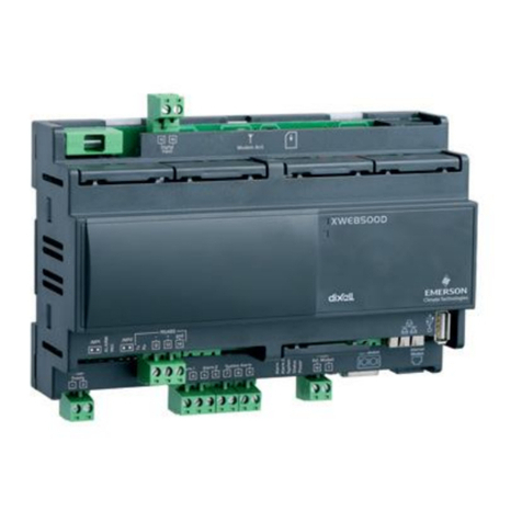
Emerson DIXELL XWEB5000 PRO Wiring diagram

XWEB5000 PRO
(V.1.0)

15920 1082 0 XWE B500 0 PRO STP GB r1.0 25.1 1.202 0.docx XWEB5 000 P RO 2/20

15920 1082 0 XWE B500 0 PRO STP GB r1.0 25.1 1.202 0.docx XWEB5 000 P RO 3/20
TABLE OF CONTENTS
1. PRODUCT DISPOSAL (WEEE)................................................................................................5
2. THE RECIPIENTS OF THIS MANUAL.......................................................................................5
3. PACKAGE.............................................................................................................................6
4. TECHNICAL DATA.................................................................................................................7
5. INSTALLATION......................................................................................................................8
5.1 XWEB..............................................................................................................................8
5.2 CONTROLLERS.............................................................................................................. 10
5.2.1 CONFIGURATION FORXC400/600/800/900 and XH200/300/400SERIES........................ 12
5.2.2 CONFIGURATION FORXJA/XJP/XJM MODELS........................................................... 12
6. LOCAL CONNECTIVITY........................................................................................................ 13
7. REMOTE CONNECTIVITY ..................................................................................................... 13
7.1 GENERAL AND MINIMUM REQUIREMENTS...................................................................... 13
7.2 DESKTOP SOFTWARE REQUIREMENTS (PC)................................................................... 14
7.3 SOFTWARE MOBILE REQUIREMENTS (SMARTPHONE/TABLET)....................................... 14
7.4 CONNECTIVITY WITH CROSS CABLE.............................................................................. 15
7.5 INTRANET CONNECTIVITY (“OR LAN CONNECTION”) AND VPN ........................................ 16
7.6 INTERNET CONNECTIVITY ONPUBLIC IP........................................................................ 17
7.7 WIFI CONNECTIVITY....................................................................................................... 18
8. OPERATIVE PROCEDURES.................................................................................................. 19
9. SYSTEM DATA.................................................................................................................... 19
10. TRADEMARKS..................................................................................................................... 19
11.NOTES................................................................................................................................ 20

15920 1082 0 XWE B500 0 PRO STP GB r1.0 25.1 1.202 0.docx XWEB5 000 P RO 4/20
CAUTION: TO PREVENT FLAMES FROM DEVELOPING OR ELECTRIC SHOCK,
AVOID ANY CONTACT BETWEEN THISDEVICE ANDRAIN OR WATER
CAUTION: TO REDUCE THE RISK OF ELECTRIC
SHOCK, DO NOT REMOVE THE COVER IT DOES NOT
CONTAIN ANY PARTS THAT REQUIRE SERVICING BY
THE USER ALWAYS HAVE QUALIFIED STAFF
PERFORM THE PROCEDURES.
THE SYMBOL OFTHE LIGHTNING BOLT INSIDE AN
EQUILATERAL TRIANGLE IS USED TO ALERT THE
USER OF THE POTENTIALLY DANGEROUS NON-
INSULATED ELECTRICAL VOLTAGES
THE SYMBOL OFTHE EXCLAMATION MARK INSIDE
AN EQUILATERAL TRIANGLE IS USED TO WARN THE
USER THAT HE/SHE MUST PAY CLOSE ATTENTION
TO THE TOPIC COVERED IN THIS MANUAL
CAUTION
This device must be installed exclusively byservice staff with suitable technical
training and experience,who are aware of the dangers that they are exposed to.
The operationsdescribed herein are set forth exclusivelyfor the service staff. The
user is not enabled to open the device.
CAUTION
Use only modems and usb-donglesofficially supported by this monitoring unit. Dixell
srl. cannot be held responsible for any type of damage resulting from the use of
unsupported devices.
CAUTION
Dixell srl reserves therightto amend this manual withoutprior notice. The latest
available version can be downloaded fromthe internetsite.
CAUTION
Immediately after the powerfailure,no new data is recorded; all recorded data is
kept in non-volatile memory. The memory is electronic and no data is kept or
conveyed to other media such aspaper. When the memory isexhausted,the oldest
data is lost to store the most recent data. The product provides memory
consumption indicationson the user interface.The device does not have its own
power supply. The recording interval can be configured from a minimum of 30
seconds to a maximum of1 day. The duration ofthe recordings depends on the
interval and the number of points configured for each device in configuration. One
yearof data logging is guaranteed for 2 analog resources with an interval of 15
minutes, per configured device. Selecting other resources can affect storage
performance.
CAUTION
This is a class A product. It can cause radio-interference in residential
environments. Should this occur,the user should take suitable countermeasures
CAUTION
Dixell srl reserves therightto vary the composition of its products without prior
notice to the customer,ensuring the identical and unchanged features of the same.

15920 1082 0 XWE B500 0 PRO ST P GB r 1.0 25.1 1.202 0.docx XWEB5 000 P RO 5/20
CAUTION
The customer shall bear full responsibility and risk for product configuration in order
to achieve the results pertaining to installation and/or final equipment/system. Upon
the customer's request and following a specific agreement, Dixell s.r.l. maybe
present during the start-up ofthe final machine/application,as a consultant,
however, under no circumstances canthe company be held responsible for the
correct operation of the final equipment/system.
CAUTION
Since Dixellproducts form partof a very high level of technology, a
qualification/configuration/programming/commissioning stage is required to use
them as best as possible.Otherwise,these products maymalfunction and Dixell
cannot be held responsible. The productmust notbe used in any way thatdiffers
from thatstipulated in the documentation
1. PRODUCT DISPOSAL (WEEE)
With reference to the DIRECTIVE 2012/19 / UE OFTHE EUROPEAN PARLIAMENTAND OF THE
COUNCIL of 4 July 2012 on Waste Electrical and Electronic Equipment (WEEE), and to the relevantnational
implementation regulations, we inform you thatusers of EEEin households:
➢there is an obligation not to dispose of WEEEas mixed urban waste and to separate waste collection of
WEEE;
➢Public orprivate collection systems required by local laws must be used for disposal. It is also possible,
at the end of its life,to return the equipmentto the distributor in case of purchase of a new one.
➢This equipmentmay contain hazardous substances;improper use or incorrect disposal could have
negative effects on human health and the environment.
➢The symbol shown on the product or on the packaging indicatesthat the product must be treated
with separate waste.
➢In case of incorrect disposal,sanctions can be applied as established by the local laws on waste
disposal.
2. THE RECIPIENTS OF THIS MANUAL
The contents of this manual are intended for professionalusers, such as XWEB installers. It may also be of
use to the administratorof the network that it isconnected to.
The mechanical product drawings required for any form of intervention and the possible network
configurationsare all an integral part of this manual.

15920 1082 0 XWE B500 0 PRO ST P GB r 1.0 25.1 1.202 0.docx XWEB5 000 P RO 6/20
3. PACKAGE
Before opening the package make sure that the packaging is intact and that there is no sign of impact or
tampering. Before starting anyoperation, itis necessary to check that the XWEB boxcontains:
•1 XWEB 5000 PRO unit
•1 Power cord
•2 brackets for RACKmounting
•8 screws for the brackets
•Removable female connectors (2x2ways, 2x3ways 1x6ways)
•4 feet forTABLEmounting
•6 Jumpers
•1 DVI-VGA Converter
•1 Installation manual
•2 ferrites
If one of the following parts is damaged, promptly contact your dealer.
You may also receive a modem or a wifi dongle- which will not be included in the same package - as a
package option.When working with a modemconnection, always check that the type of modem you are
about to install is a Dixell approved model; as it cannot be held responsible for the malfunctioning of devices
not expressly approved by it.

15920 1082 0 XWE B500 0 PRO ST P GB r 1.0 25.1 1.202 0.docx XWEB5 000 P RO 7/20
4. TECHNICAL DATA
Power supply
100-230 V
Power
60 W
Voltages and maximumcurrent applicable to the
AUX terminals 1-2-3
AUX1-2-3 24V
AUX1 8A
AUX2-3 4A
Operating conditions (temperature,humidity,
special conditions)
0/45°C R.H.5÷95% (non-condensing)
Electrical safety
LVD - COUNCIL DIRECTIVE 2014/35/EU
Electromagnetic compatibility
EMC - COUNCIL DIRECTIVE 2014/30/EU
Internal battery and RTC accuracy
Rechargeable and non-removable lithium battery.
The accuracy of the RTC is ± 35 ppm, the
maximum driftof the clock in a year is therefore
about 18 minutes
Approvals
The system consisting of this controland
monitoring unit and Dixelltemperature meters
compliantwith the EN13485 standard complies
with the EC regulation no. 37/2005 and in
particular with the EN12830 standard.
Temperature recorders for the transport and
storage and distribution of chilled,frozen, deep-
frozen and ice-creamproducts (UNIEN 12830, S,
A, 1, measurement range corresponding to the
class of connected devices)
CAUTION:
The terminal block to connect AUX1, AUX2 and AUX3 relays
cannot be used to pilot high voltage loads directly (higher to 24V).
Use an intermediate low voltage circuit and/or suitable remote
switch.

15920 1082 0 XWE B500 0 PRO ST P GB r 1.0 25.1 1.202 0.docx XWEB5 000 P RO 8/20
5. INSTALLATION
5.1 XWEB
For installation, the XWEB-EVOsystem must not be opened in any way. If the boxis opened, the warranty
will lapse.
XWEB-EVOcan be installed in various ways based on the typeof user interface access that you wish to
provide for the finaluser. Below is a description of the most complete procedure, i.e. where the system's
user interface can be used entirely in localcontrol. If the systemhas already been configured and you wish
to use the interface through modemor Ethernet, points 5 to 9 may be optional. The particular features of
these types of connectivity are described herein.
To set up a local installation of the system, we recommend having the following equipment available:
•a Phillips and a slot-head screwdriver;
•a PS2 or USB mouse;
•a PS2 or USB keyboard;
•a monitor with a DVI or VGA connector. We recommend using high
definition monitors
The system must be installed referring to the figure below, which
illustrates the rear XWEB-EVO panel, and following the points listed
here:
1. The product hasa power plug with protective earth.Make sure that
the electrical systemhas a protective earth connection;
2. Attach the XWEB-EVO device in the position it will be used in. If it is
installed on a table, set the rubber feet up in the holes on the
underside of the device. For rack installation,on the other hand, use
the supplied brackets and screws.
3. Connect it to the power mainsby the supplied power cord (1). Set
the power plug up so thatit is easily accessible at all times.Note:
Do not turn the system on;
4. Connect the RS485, the relays and digital inputs (2)(4)(16)(14)(17),
and end and/or polarise the line, if necessary (3)(15);
5. Connect any telephone linesand/orLANnetwork cables(7);
6. Connect any keyboard and mouse (9)(10)(11);
7. Connect any monitors (12);
8. Connect any printers(11);
9. Connect any modem: internal modem(13)or external modems(05).
The cable must notbe anylongerthan 10 m.
10. It is now possible to turn the systemon by pressing and releasing
(18);
For operator safety and to
protect the XWEB
system, before
performing any sort of
operation, connect the
system to the electrical
network by the supplied
cable. Power cord must
be the last to be removed.
•Avoid direct passage between
operators as much as possible
(to avoid electrostatic induction
and subsequent discharges);
•If the electrical voltage supply
differs from the required rating,
this could seriously damage the
system;
•Connection errors (and
connections that differ from the
prescribed ones) can pose a
danger to operator safety and
cause faults in the system and
to the instruments that are
connected to it;
•Insert one or more easily
accessible disconnecting
devices to the exterior of the
device to separate the device
from the power mains;
•Do not use the device in
environments with flammable
gases.
•Do not modify the device in any
way.
15920 1082 0 XWE B500 0 PRO ST P GB r 1.0 25.1 1.202 0.docx XWEB5 000 P RO 9/20
LED
LED
Colour
Description
Pwr
Green
On when the systemis powered
HDD
Blue
On when the discexecutes physicalwriting operations
Rec
Blue
On when the systemis recording data
Ser1/Ser2
Blue
On when the systemis reading and/orwriting on serialport485
Mdm
Blue
On when the systemruns operations with the analogue modem
DI1/DI2
Blue
On when the systemdetectsthe digitalinput as being active
Aux1/Aux2/Aux3
Blue
On when the systemsets the relay output as active
Alarm
Red
On when the systemdetectsan alarm
XWEB-EVOcan also operate withouthaving a screen, mouse and keyboard attached. For example, it is
possible to use this initial systeminstallation configuration and then disconnectthem definitively if you only
intend to setup access fromthe remote station.If you intend to use external peripheral devices, always
connect them to the unit before turning it on. Caution: always and only connect the external peripheral
devices before turning on XWEB-EVO. If necessary, consult the instructions manual for the individual
connected device.
When the system hasbeenlaunched,the home page will appear (also known as the login page) on the
screen connected to XWEB-EVO. Enter user name and password to login.
Note that the user interface for the connection is always the same,regardless of what type of access has
been set up: local PC,Intranet or Internet.

15920 1082 0 XWE B500 0 PRO ST P GB r 1.0 25.1 1.202 0.docx XWEB5 000 P RO 10/20
5.2 CONTROLLERS
XWEB has at least one RS485 serial port, on which the line of the controller devices can be connected. If
there are more serials,more device linescan be served.
Most Dixell controller devicesare equipped with an RS485 serialoutput and can be connected without the
need for any additional module or connection cable. To make sure of this possibility, check the
characteristics of the controller in its manual.
Some Dixell devices however, may not be direct, but it can be obtained via the small external Dixell
XJRS485 or DixellXJ485 converter.It converts the controller outputfrom"TTL" (five wires) to "485" (two
wires). If you need to use the TTL / 485 converter, please payattention in:
•Keep the TTL cable away fromany source of electromagnetic disturbance
•Connect each XJ485 module to the instrumentwith the TTL cable supplied with the module itself
•Mark the polarityof output 485 which must be respected when connecting the instruments to the
network
Below is a list of operating tipsto obtain the best result in terms of instrument network reliability, RS485
serial connection:
•The serial line cable can be of the two-wire type plusshield,with a minimumsection of 0.5mm2 (eg
the BELDEN 8772). This cable is recommended for its technical characteristics and for maint aining
the quality of the electrical signal;
•The serial line cable must reachall the instrumentstations: check the plant layout and the various
distances thatthe cable will have to travel;
•The serial line cable can reach a maximum length of 1 km
•Respect the polaritiesindicated on the instrument withthose of the cablesleading to the serial line;

15920 1082 0 XWE B500 0 PRO ST P GB r 1.0 25.1 1.202 0.docx XWEB5 000 P RO 11/20
•Do not branch into the line:
Correct
Mistaken
•Keep the serial cable away from power cables and any possible source of electromagnetic
disturbance.Mountthe supplied ferrites on the serialports asshown in the figure
•Do not connect the shield of the serial cable to the earth of the electrical system
•Do not connect the “Gnd” terminal.
•Drawa map of the installation you are performing: it will beusefulboth in case of problems and in
case of future changes; the serial line must reach all the stations where the instruments must be
controlled.
On the same line, each controller is normally programmed with its own unique serialaddress, t hrough the
Adr parameter. Refer to the installation manual of the instrument itself for the access and modification
procedure. To obtain a simple description of the categories to which they belong,divide the programming of
the addresses progressively. Some special cases are listed on the following pages.
To keep the RS485 line balanced, the ends must be terminated with a 1500Ω resistor. If the XWEB is at one
end of the RS485 line, it is advisable to insert the 120Ω termination resistor on the last instrumentand on the

15920 1082 0 XWE B500 0 PRO ST P GB r 1.0 25.1 1.202 0.docx XWEB5 000 P RO 12/20
XWEB. To activate the EOL resistor,insertthe jumper in position2 (word TERM).DONOTinsert the jumper
if the XWEB is in the middle of the RS485 line.
Notes on the use of polarization resistors (POL-, POL +)
In order to avoid false signals on the bus, polarization resistors must be inserted.It is important to note that
they must be inserted in one and only one place in the network, otherwise the communication will
deteriorate;the node in which they are inserted is irrelevant even if it could be convenient to do so on the
XWEB, checking that the other instruments of the serialnetwork have not already integrated and permanent
them.
5.2.1 CONFIGURATION FOR XC400/600/800/900 AND XH200/300/400 SERIES
These instruments have two serial addresses and must be configured in the same way. Refer to the
instrument's installation manual to learn about the access and editing procedures.
5.2.2 CONFIGURATION FOR XJA/XJP/XJMMODELS
XJA/XJP/XJM series instruments are configurable with one or more modbus addresses. Refer to their
installation manual for the configurationprocedures.

15920 1082 0 XWE B500 0 PRO ST P GB r 1.0 25.1 1.202 0.docx XWEB5 000 P RO 13/20
6. LOCAL CONNECTIVITY
Local access with a screen, mouse and keyboard directly connected to the XWEBis the most common and
most frequently used type of access for the user interface. The system can work even without these
peripherals connected and it is possible,for example, to use this mode only for the initial configuration of the
system; and then disconnectthem even permanently if access is provided only froma remote location.
XWEB supports PS / 2 mouse and keyboard or USB mouse and keyboard which can be connected to any
available USB port.The screen that can be connected to XWEB must be of the typewith DVIconnector (or
VGA using the adapter supplied as an accessory) and have a minimum resolution of 1024x768. We
recommend using a screen witha resolution higher than 1024x768 pixels. Check your display's instruction
manual for supported resolutions.
7. REMOTE CONNECTIVITY
7.1 GENERAL AND MINIMUM REQUIREMENTS
The user or the installer of XWEB can access its user interface,as well as locally with
screen, keyboard and mouse, also through a PC that mustbeconnected and configured
to be able to communicate with the XWEBnetwork. The XWEB Ethernetport that must
be used for remote connectivity must be theLAN port, asshown in the image below.
Attention: due to its technical characteristics and to maintaining the quality of the
electrical signal, it isrecommended touse shielded ethernetcables; if it isnot possible to
use shielded cables, apply the supplied ferrites; the image below shows the ferrite
applied to a LAN port.
Performances usinga PC as a user interface terminal is greater than the use of local connectivity,
therefore it is recommended to use it especially in the first configuration phase. The user interface available
remotely is the same as available locally.

15920 1082 0 XWE B500 0 PRO ST P GB r 1.0 25.1 1.202 0.docx XWEB5 000 P RO 14/20
The terminal used must comply with and support the minimum characteristicsfor the installation and use of
the following software.
7.2 DESKTOP SOFTWAREREQUIREMENTS (PC)
Browser
Support
Minimum Version
Microsoft Edge
SUPPORTED
16+
Mozilla Firefox
SUPPORTED
54+
Google Chrome
SUPPORTED
58+
Apple Safari
SUPPORTED
10.1+
Opera
SUPPORTED
44+
Microsoft Internet Explorer
NOT SUPPORTED
7.3 SOFTWAREMOBILE REQUIREMENTS (SMARTPHONE/TABLET)
Browser
Support
Minimum Version
Apple iOSSafari
SUPPORTED
10.3+
Android Google Chrome
SUPPORTED
58+
Android MozillaFirefox
SUPPORTED
54+
All newer computers are capable of meeting these requirements. However, it is advisable to use the advice
of a computer expert to evaluate the computers to be purchased and / or already in your possession.
In the following sections,general information on possible network configurations will be provided.Right from
the start, we recommend that you make use of ITexperts and / or your network administrator to evaluate the
configurationsbest suited to your needs.
Softwares suchas antivirus, firewall,toolbarscan preventthe correct display of the XWEB pages. We
recommend checking the configuration of these softwares and adding the XWEBIP address to their list of
safe sites. For firewalls, make sure that ports 80 and 22 are mappedto the XWEB so that it can be
reached from the outside.

15920 1082 0 XWE B500 0 PRO ST P GB r 1.0 25.1 1.202 0.docx XWEB5 000 P RO 15/20
7.4 CONNECTIVITY WITH CROSS CABLE
Local access from the PC is the fastest way to manage setup. It is possible to connecta PC to XWEB -EVO
through the network interface supplied with an ‘RJ45 Ethernet connector’. The connection between t he t wo
must be set up using a crossnetwork cable (aka'cross cable'). This cable is available at any computer store.
Once the physicalconnection has been setup, launch the browser on your PC and enter the following in the
addressbar http://192.168.0.200 (XWEB-EVO default address).The connection procedure is complete when
the login page opens up. Enteruser name and password to start using your XWEB-EVO.
Caution: a pre-requisite to setting the connection up correctly is that the XWEB-EVO address and network
interface address on yourPC need to have a compatible IP class. For example, with an XWEB-EVO network
interface configured with 192.168.0.200, the network interface on your PC can be configured with
192.168.0.15
In order to configure the networkinterface of yourPC, administration privileges are normally required. Refer
to the documentation of your PC's operating system.The following figure shows the stepsto be taken to
configure the network interface of a PC with WINDOWS.

15920 1082 0 XWE B500 0 PRO ST P GB r 1.0 25.1 1.202 0.docx XWEB5 000 P RO 16/20
7.5 INTRANET CONNECTIVITY (“OR LAN CONNECTION”) AND VPN
This type of connection willallowyou to access XWEB fromany PC connected to the local network. This
type of connectionmust also be used to configure the XWEBfor connection from the internet via VPN
(Virtual Private Network). This last type of connection,once established,brings your PC - connected to the
internet - to become partof the local XWEB network.
Attention: the connection to yourcompany's localnetwork is assumed to be managed by qualified personnel
and / or by the network administrator.Which must beable to assign a valid IP address to the XWEB and be
able to provide - foryour PC - any software and credentials if you want to use a VPN networkfor access.
Before connecting the XWEB to the network, check that the IP address you wish to use for the XWEB is
actually free and therefore usable. You could perform a PING to thataddress and if at least one reply is
received at the PING, the address must be changed asit is alreadyused.
Example:
Before connecting the XWEBto the network, please configure its IP (and other network configuration
parameters) using the direct local connection (with screen, keyboard and mouse) or with the local PC
connectionwith crossed cable. Once the network parameters have been set, the XWEB can be connected to
the local network with a standard RJ45 cable. Connect fromyour PC to XWEB by opening the browser and
entering the XWEB IP address in the address bar. The default address is: http://192.168.0.200. Storethe
address in the listof favorites.

15920 1082 0 XWE B500 0 PRO ST P GB r 1.0 25.1 1.202 0.docx XWEB5 000 P RO 17/20
7.6 INTERNET CONNECTIVITY ON PUBLIC IP
This type of connection willallowyou to directly accessXWEB fromany PC connected to the internet without
having to install -on your PC - any additional software.
Attention: the connection to the Internet presumesto be managed by qualified personnel and / or
by the networkadministrator.
In order to connect yourXWEBto the Internet, you need a 'public and static IP address',which
must be specifically requested fromyourISP (Internet Service Provider). Tell yourISP that you want to install
a webserver: this will help them recognize your needs and provideyou with an adequate connection. It is
highly recommended to obtainall the details of the supply contract for the management of any future
connectionproblems.
Connection to the internetis possible in the presence of a router. Its configuration, as well as that of XWEB
depend on the data provided by your ISP. Depending on the type of contract, the provider can supply the
router or the customer can purchaseit separately.
Provide your ISP and / or network administratorwith the XWEBports (LAN side)
•80 (used for HTTP access)
•22 (used for SSH logins)

15920 1082 0 XWE B500 0 PRO ST P GB r 1.0 25.1 1.202 0.docx XWEB5 000 P RO 18/20
7.7 WIFI CONNECTIVITY
This type of connection will allow you to directly access XWEB from a device equipped with a Wi-Fi
connection, or to allowXWEB to access an already configured Wi-Fi network. A prerequisite for these types
of connectivity is the installation of the WIFIdongle in the XWEB USB port.
ATTENTION: Only usedongles officially supportedbythismonitoringunit.
i. Connecting a mobile device to the XWEB access-point
XWEB is normally supplied preconfigured in this mode so that the user can search with his PC / smartphone
/ tablet to an "XWEB-PRO"SSID network. The default password is “dixellxwebpro”.
i. Connection of XWEBto existing Wi-Fi network
XWEB can be connected via Wi-Fi to a Wifi-AccessPoint already presenton thesite. In this case,you need
to temporarily access the XWEB interface with another type of connection (typically with a crossed cable) to
change the connection configuration parameters.
Configuration changes can be made by the user after accessing the user interface fromthe
System→Settings→Networkmenu.
ATTENTION: no access to port 22 service isprovided in Wi-Fi.

15920 1082 0 XWE B500 0 PRO ST P GB r 1.0 25.1 1.202 0.docx XWEB5 000 P RO 19/20
8. OPERATIVE PROCEDURES
For the operating proceduresplease refer to the OPERATING MANUAL, in the "Download Manuals" section
of the website http://www.dixell.comwhere the updated version is available.
9. SYSTEM DATA
Fill in the table below,make a xerox copy and keep it near the XWEB.
HostName
___________________________ [example:myXWEB001 ]
IP Address
___________________________ [example:192.168.0.123 ]
Gateway
___________________________ [example:192.168.0.1 ]
DNS
___________________________ [example: 8.8.8.8 ]
SMTP
___________________________ [example:192.168.0.14 ]
E-mail Address
___________________________ [example: myXWEB001@company.com ]
Modem
___________________________
Telephone number
___________________________
10. TRADEMARKS
Consider It Solved and Intelligent Store are trademarks and Emerson Climate Technologies and the
Emerson Climate Technologies logo are service marks and trademarks of Emerson Electric Co.
Windows and Internet Explorerare registered trademarks ofMicrosoft Corporation in the United States and
othercountries.
Oracle and Java are registered trademarks of Oracle and/or its affiliates.
Google is a registered trademarkof Google Inc.
Firefox is a registered trademark of the Mozilla Foundation.
Yahoo! is a registered trademark of Yahoo!Inc.
Linux is a trademark registered to Linus Torvalds.
Othernames may be trademarks of their respectiveowners.

15920 1082 0 XWE B500 0 PRO ST P GB r 1.0 25.1 1.202 0.docx XWEB5 000 P RO 20/20
11. NOTES
______________________________________________________________________________________
______________________________________________________________________________________
______________________________________________________________________________________
______________________________________________________________________________________
______________________________________________________________________________________
______________________________________________________________________________________
______________________________________________________________________________________
______________________________________________________________________________________
______________________________________________________________________________________
______________________________________________________________________________________
______________________________________________________________________________________
Table of contents
Other Emerson Server manuals

Emerson
Emerson Avocent ACS 6000 User manual

Emerson
Emerson Dixell XWEB300 User manual

Emerson
Emerson PACSystems RX3i User manual

Emerson
Emerson ATCA-7368 Quick start guide

Emerson
Emerson Dixell XWEB300 User manual

Emerson
Emerson Knurr DCM User manual

Emerson
Emerson Lumity XWEB5000 PRO Wiring diagram

Emerson
Emerson Avocent ACS 6000 User manual

Emerson
Emerson Avocent ACS 6000 Operating manual

Emerson
Emerson Centellis 2000 Shelf Release 3.0 User manual