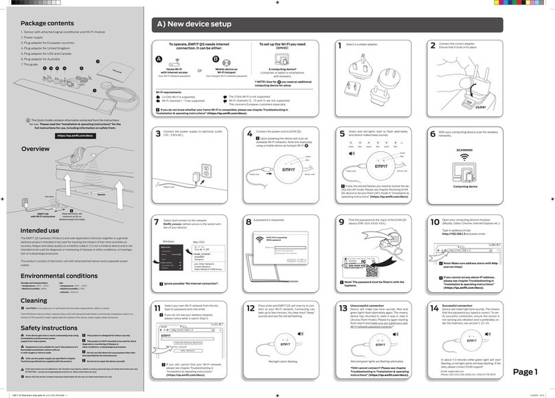
Emfit SafeBed User manual

Applicable to products:
Control unit D-1070-2G, t66 v.1.2.3
Bed sensor L-0656SLC
04 April 2013
Emfit, the Emfit logo and Safebed are either registered
trademarks or trademarks of Emfit Ltd.
Copyright © 2002–2013 Emfit Ltd. All right reserved. Patented,
patents pending (see list at www.emfit.com).
Instructions for Use
Bed Exit and Occupancy Monitor

2
ENGLISH
TABLE OF CONTENTS
1.
Advarsler ......................................................................................................................................................... 3
1.1. Vigtig information læs før enheden tages i brug........................................................................................ 3
1.2. Utilsigtet justering af indstillinger i styreenhed:...................................................................................... 3
2.
SYMBOLER I DENNE MANUAL ....................................................................................................................... 3
3. INTRODUCTION ...............................................................................................................................................4
3.1. Anvendelsesformål ................................................................................................................................ 4
4. PACKAGE CONTENTS ....................................................................................................................................4
5. GENERAL .........................................................................................................................................................4
5.1. Control enhed (picture 1)....................................................................................................................... 4
5.2. Senge sensor (picture 6)....................................................................................................................... 5
6. SETTING UP THE DIP SWITCHES..................................................................................................................5
6.1. Indstilling af seng exit forsinkelse (DIP switch # 1 - # 3) ............................................................................ 5
6.2. DIP switch #4 - #6 settings ..................................................................................................................5
6.3. Justering af lydstyrken (switches #7 and #8)..............................................................................................6
7.
I SÆT BATTERIER OG BATTERILEVE TID .............................................................................6
8. EXTERNAL POWER SUPPLY .........................................................................................................................6
9. CONNECTORS AND CABLES.........................................................................................................................7
10. INSTALLATION OF THE CONTROL UNIT....................................................................................................7
10.1. With wall mounting bracket..................................................................................................................7
10.1. With bed side clip.................................................................................................................................8
11. INSTALLATION OF THE BED SENSOR........................................................................................................8
12. SW1 PRESS SWITCH (picture 21)................................................................................................................8
12.1. ON/OFF switch.....................................................................................................................................8
12.2. Acknowledgement switch....................................................................................................................8
12. CALIBRATING THE “PRESENCE / ABSENCE” SENSITIVITY...................................................................8
13.1. Doing calibration..................................................................................................................................8
14. SIGNAL LIGHTS (picture 22) ........................................................................................................................9
14.1. Green – Presence................................................................................................................................9
13.2. Blue – Device on/standby....................................................................................................................9
13.3. Red – Malfunction ...............................................................................................................................9
15. CHECKS ..........................................................................................................................................................9
15.1. Weekly checks ....................................................................................................................................9
15.2. Start-up and monthly checks ..............................................................................................................9
16. TROUBLESHOOTING ..................................................................................................................................10
17. CLEANING.....................................................................................................................................................10
18. DISPOSAL OF THE DEVICE AFTER USE..................................................................................................10
19. DECLARATION OF CONFORMITY (EU).....................................................................................................10
20. EMFIT LIMITED WARRANTY STATEMENT...............................................................................................10
21. TECHNICAL SPECIFICATIONS...................................................................................................................12
21.1. Control unit.........................................................................................................................................12
21.2. Sensor ...............................................................................................................................................12
21.3. Ambient conditions............................................................................................................................12
21.4. Product class.....................................................................................................................................12
22. ELECTROMAGNETIC CONDITIONS..........................................................................................................13
23. MANUFACTURER ........................................................................................................................................16
24. Appendix – Related pictures......................................................................................................................16

3
Dansk
1. Advarsler
1.1. Vigtig information. læs før enheden tages i brug.
•Må ikke anvendes i situationer, hvor en forsinkelse i ankomsten af passende pleje, kan føre til en potentielt livstruende situation.
•Denne enhed er kun beregnet til at blive brugt som en hjælp til en omsorgsperson.
•Kæledyr kan give falske meddelelser eller forhindre en meddelelse, når nødvendig, hvis de går eller ligger på en seng som er
udstyret med denne enhed.
•Brug ikke denne enhed til andre end specificeret af producenten formål..
•Tilslut ikke enheden til andre end de af producenten andre enheder.
•Forsøg ikke selv at reparere enheden.
•Enheden er designet til at blive brugt i det elektromagnetiske miljø og betingelserne på siderne 13-16. Klienten eller brugeren af
enheden skal sikre, at det kun anvendes i de angivne omgivelsesbetingelser.
•Installer ikke apparatet i nærheden af eller oven på en anden enhed. Men hvis dette ikke kan undgås, skal brugeren sikre, at
enheden fungerer på normal vis.
•Brug ikke X1, X2 eller X3-stik til andre end specificeret af producenten formål. Tilslut ikke stikkene til f.eks telekommunikation eller
lokalnet.
•hvis denne enhed anvendes sammen med en madras fyldt med en kompression pumpe kan enheden ikke altid fungere
normalt i nogle tilfælde.
•Enheden må ikke blive våd.
•Fjern batterierne, hvis enheden ikke er i brug, eller når den opbevares i en længere periode. Alkaline batterier kan selvaflade, og
begynde at lække /forurene enheden.
•Brug ikke genopladelige batterier eller lithium-ion-batterier!
Genopladelige eller lithium-ion-batterier indebære en risikoen for smeltning, og kan ødelægge enheden eller forårsage mulig fare for
brugeren.
1.2. Utilsigtet justering af indstillinger i styreenhed:
•Justering af lydstyrken kan medføre at anmeldelsen ikke bliver hørt.
•Forkert placering af DIP-switche kan forstyrre den normale drift af enheden.
•Ved at trykke på ON / OFF / Reset (SW1) kontakten for længe, vil medføre at enheden slukker.
2. Symboler i denne MANUAL
De følgende instruktioner er designet for at sikre den personlige sikkerhed for brugeren og beskytte denne enhed eller enhver enhed
tilsluttet til det fra skader. Disse instruktioner bruger symboler til at gøre brugeren opmærksom på anvisningerne. Symbolerne fungerer
som sikkerheds- og advarselsskilte. Symbolerne og deres forklaringer er som følger:
Dette symbol betyder, at hvis vejledningen ikke overholdes, kan situationen føre til dødsfald eller alvorlig personskade.
Dette symbol betyder, at afsnit indeholder vigtige oplysninger til brugeren.
Dette symbol angiver den maksimale udnyttelse og opbevaringstemperatur.
Alle rettigheder reserverede. Kopiering helt eller delvist er forbudt uden skriftligt samtykke fra indehaveren af ophavsretten. Enhver trykt eller elektroniske
oplysninger er kun vejledende, og vi tager ikke noget juridisk ansvar for rigtigheden af disse oplysninger. Vi bevarer retten til at foretage ændringer med
henblik på løbende at forbedre vores produkt.

4
ENGLISH
3. INTRODUCTION
•Disse instruktioner beskriver brugen af Emfit Safebed sengenalarm.
•Brug kun enheden under de omgivende forhold, der er angivet af fabrikanten. For detaljerede oplysninger henvises til "Tekniske
specifikationer" i denne vejledning..
•Følg alle instruktioner i dette dokument vedrørende installation, brug og rengøring af enheden.
•I overensstemmelse med den påtænkte anvendelse, der er defineret i afsnit 3.1 nedenfor, er Emfit Safebed ikke en medicinsk
anordning som defineret i direktivet om medicinsk udstyr 93/42 / EØF.
3.1. Anvendelsesformål
Emfit Safebed er beregnet til at hjælpe med at udføre sensorisk seng-udgang, overvågning af belægning og underrette personalet,
hvis personen, der ligger på en madras udstyret med Sengesensoren, forlader sengen eller ikke vender tilbage til den inden for forudbestemt tid.
NOTE
Fabrikanten kan ikke garantere, at enheden vil registrere alle seng-udgangspisoder.
Der kan også forekomme en meddelelse om falsk seng-udgang.
3.3. OM DENNE MANUAL
Læs alle advarsler og påmindelser i denne vejledning med omhu for at undgå farlige situationer og skader.
4. INDHOLD I KASSEN
• A control unit and two screws to attach the lid (picture 1)
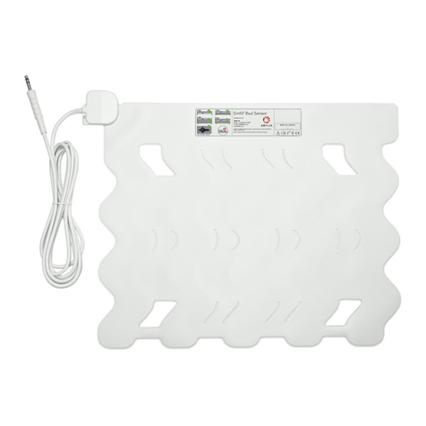
• A bed sensor with two pieces 3M double-sided tape to fix the sensor (picture 6)
• A wall mounting bracket with two screws and two plugs (picture 7)
• Clip for bed side attachment (picture 8)
• This manual
• Two AA batteries
• Optionally a power supply (GlobTek model no: GTM41060-1505 and P/N: WR9QA3000LCP-N-MNK) (picture 2)
5. GENERAL
5.1. Control unit (picture 1)
The control unit activates for bed occupancy monitoring after it has noticed movements or micro-movements for 1 minute. After
activation for occupancy monitoring, a notification is triggered if no movements or micro-movements are detected for at least 3 or 5
seconds (adjustable by DIP switch, see Chapter 6).
The control unit operates with 2 pcs AA size 1.5 V alkaline batteries. An optional AC adapter is available. Do not use any power supply
other than that provided by Emfit Ltd. (model no. GTM41060-1505 and P/N:WR9QA3000LCP-N-MNK, manufactured by Globtek) (pic-
ture 2).In the event of a power failure, two high-quality 1.5V AA alkaline batteries can be used as an emergency power supply. Do not
use any rechargeable batteries or lithium-ion batteries! Rechargeable or lithium-ion batteries carry the risk of melting, ruining the device
and causing possible danger to the user.
The control unit has an input connector for the bed sensor (X3) and power supply (X1). The device also has a connector (X2) to transfer
the notification to e.g. a nurse call system, a personal emergency phone or an external wireless transmitter.
Nexttotheinputconnector,there isa pushbutton (SW1) that canbe usedtoacknowledgea notificationorasanon/off switch. (picture 3)
The control unit has 8 DIP switches (picture 4) to select the settings and a rotary switch to adjust the sensitivity of the device. (picture 5)

5
Dansk
5.2. Bed sensor (picture 6)
The bed sensor produces a millivolt alternating current when detecting movement. The control unit calculates the frequency and scale
of the movement from this signal and, on this basis, detects the person's presence in the bed. Heartbeat causes micro-movement that
allow the device to detect the person's presence. When there is no micro or other movement, it recognizes this as the individual being
absent and it gives a notification both by sound and via dry-contact optocoupler. There are no particular size or weight limitations, but sen-
sitivity and the ability to recognize a user’s micro-movements and thus, presence in bed, need to be tested in each case.
6. SETTING UP THE DIP SWITCHES
Open the lid of the control unit by lifting it from the side (picture 9). Inside, you will find eight DIP switches that are used to select the
desired functions (picture 4). Remember to select the desired settings using the DIP switches before using the device.
The control unit has the following factory settings. DIP 1, 2, 3, 4, 5, 6, 7 and 8 all OFF (down). With these settings:
• Bed exit notification delay is 3 seconds.
• Output is in pulse mode
• The SW1 switch acts as the On/Off switch which means that the device can be switched on or off by pressing the switch for three
(3) seconds.
• The notification sound is “very loud”.
Afbryd altid 220v. strømforsyning, før du åbner låget.
Afbryd altid strømforsyning og fjern batterierne, før opsætning af DIP-kontakter.
6.1. Indstilling seng exit forsinkelse (DIP switch # 1 - # 3)
Tidsforsinkelse Switch # 1 Switch #2 Switch #3
Kortest (3 - 4 sec) OFF (ned) OFF (ned) OFF (ned)
5-7 sekunder (brug, hvis der ved korrekt
følsomheds justering kommer falske alarmer)OFF (ned) ON (op) OFF (ned)
3 minuter ON (op) ON (op) OFF (ned)
6 minutter OFF (ned) OFF (ned) ON (op)
10 minutter ON (op) OFF (ned) ON (op)
15 minutter OFF (ned) ON (op) ON (op)
30 minutterON (op) ON (op) ON (op)
6.2. DIP switch #4 - #6 settings
DIP # OFF (ned) ON (op)
#4 Stærk ekstern støj (f.eks klimaanlæg, vaskemaskine, trafik osv)
#5 kontakt output er puls-tilstand
(ca.1,5 pulse i sekundet)
kontakt output er konstant type. Brug kun når det er nødvendigt når
der ska forbindes til andre systemer. Må ikke anvendes med batterier!
strømforsyning er nødvendig på grund af øget strømforbrug.
#6 Afbryder funktion SW1 er aktiveret
(enhed kan slukkes og tændes ved at
trykke på SW1 i ca. 3 sekunder)Afbryder funktion SW1 er ikke tilgænlig (enheden er altid på).
Normal baggrundsstøj

6
ENGLISH
6.3. Justering af lydstyrken (switches #7 and #8)
Der er fire lydstyrker: Meget højt, højt, lav og mute. Fabriksindstillingen er meget højt.
Lydstyrke Switch #7 Switch #8
Meget højt OFF (down) OFF (down)
Højt ON (up) OFF (down)
Lav. OFF (down) ON (up)
Mute ON (up) ON (up)
Anmeldelses lyden stopper, når der trykkes på SW1 kontakten eller når personen vender tilbage til sengen.
Afbryd altid strømforsyning og fjern batterierne, før opsætning af DIP-kontakter.
7. Isætning af batterier og batteri levetid
Afbryd enheden fra strømforsyning, før du åbner låget.
Produktet opererer med 2 stk. høj kvalitets AA 1,5 V alkaline batterier (driftsspænding 2x1,5V = 3V). Installere og fjern batterierne som
følger:
1) Åbn låget ved at fjerne skruerne og løfte det fra den ene side
(skruerne til låget findes i posen med dele til vægmontering ). (Billede 9)
2) Isæt 2 stk. af høj kvalitet AA størrelse 1.5V alkaline batterier i enheden, efter de polaritet symboler i bunden af enheden.
Luk låget og skru skruerne i. (Billede 10)
Den nemmeste måde at fjerne et batteri er ved at løfte det fra + ende. (Billede 11)
Anslået batteritid er 3 måneder, ved brug af høj kvalitet alkaline batterier, med 2800 mAh kapacitet (2stk). Skøn er baseret på målte
batteriforbrug i forskellige forhold og derefter en beregning, hvor enheden er tændt 50% af tiden (lukket 50% af tiden) og at 50% af tiden
hvor der er nogen i sengen 75% af den tid, der er to notifikationer pr. dag og lyd notifikation er på 30 sekunder hver gang.
Når batterierne er ved at være lav, vil den røde LED begynder at blinke langsomt. Et "bip", vil høres efter hver 1,5 timer og
kontakt output vil give en lavt batteri notifikation efter hver 3 timer.
NOTE! All alkaline batteries start to leak when empty, and a leak will contaminate the device. Remember to replace the batteries
at least once a year to avoid any leaks. Remove the batteries when the device is not being used or when it is being stored for an
extended period. Disconnect the power supply briefly to test the batteries. If the batteries are empty, the red light on the control unit will
light up. The X2 connector and the connected system will also trigger a notification. Replace the batteries when necessary.
Do not use any rechargeable batteries or lithium-ion batteries! Rechargeable or lithium-ion batteries carry the risk of melting, ruin-
ing the device and causing possible danger to the user.
8. EXTERNAL POWER SUPPLY
Set up the power supply in the following manner:
1) Remove the plastic cover. (picture 23)
2) Select a suitable plug from the four alternatives. (picture 24)
3) Plug in the plug and ensure that it is not loose. (picture 25)

7
Dansk
The control unit has been designed and tested to be used with the Globtek inc. power supply model no GTM41060-1505 and
P/N: WR9QA3000LCP-N-MNK. Using any other power supply may interfere with the safe use of the device.
The power supply is fitted with a blue light which lights up when the power supply is connected. If the light is not on while the
power supply is connected to the mains, the power supply is probably faulty and needs to be replaced.
When the power supply is connected, the batteries act as backup power supply in the event of a power failure. All alkaline bat
teries self-discharge and start to leak when empty, contaminating the device. Ensure that batteries are replaced at least once a
year.
When removing the power supply from the socket, ensure that the plug part is not left in the socket. If the plug part is left in the
socket, touching or trying to remove it carries the risk of an electric shock.
9. CONNECTORS AND CABLES
Connector symbols can be found at the bottom of the control unit. (picture 3)
X1/connectorforanexternalpowersupply.OnlyuseGlobtekinc.powersupplymodelno. GTM41060-1505andP/N:WR9QA3000L-
CP-N-MNK which can be obtained as an original accessory from Emfit Ltd.
X2 / AUX connector to connect the device to a nurse call system, a personal emergency phone or an external wireless transmitter.
The connector may only be connected to a system safety voltage input with max. voltage below 25V(AC) / 60 (DC), where both poles
have been separated from the electrical network. Max. load current 100mA.
X2 (AUX) Connector Pin Order (picture 16)
From left to right:
Pin #1 Common return
Pin #2 Normally Open (NO) send
Pin #3 Normally Closed (NC) send
Pin #4 Low Battery send (NC)
Pin #5 Not in use, do not connect
Pin #6 Not in use, do not connect
Pin #7 Not in use, do not connect
Pin #8 Not in use, do not connect
X3 / sensor connector. Only use the Emfit bed sensor.
Connect the bed sensor (picture 13), the (optional) power supply (picture 14) and any connector cables (picture 15) according to the
pictures.
10. INSTALLATION OF THE CONTROL UNIT
10.1. With wall mounting bracket
1) Fix the mounting bracket onto a wall with the plugs and screws supplied. (picture 17)
2) Slide the control unit onto the wall mounting bracket. (picture 18)
3) Press the control unit down until you hear a click. (picture 19)

8
ENGLISH
10.1. With bed side clip
1) Press the control unit down to the clip (picture 20)
11. INSTALLATION OF THE BED SENSOR
• Place the bed sensor across the bed, under the mattress at approximately chest height. (picture 12)
• To prevent the bed sensor from moving, fix the sensor to the bed bottom or mattress using the double sided tape provided or e.g.
cable ties (picture 6). The tape will not leave a mark and it will come off as a whole if removed.
• Check at least once a week that the bed sensor is properly positioned.
• If you are using the bed sensor with a spring mattress, always place the bed sensor between the mattress and the mattress topper!
• Always place the bed sensor under the mattress or mattress topper, never just under the sheet. The bed sensor must not come into
direct contact with a person!
• The bed sensor is designed to last for a minimum of two (2) years placed under a foam mattress and against the hard base of a bedframe.
• With a spring mattress, the service life of the bed sensor is considerably shorter. When the bed sensor is placed on a spring mat-
tress, the user's weight and movement will cause the sensor to crumple, which may affect the sensor's performance. The manu-
facturer recommends that users replace the sensor when it starts to look crumpled. When used with a spring mattress, the sensor
should be replaced every year. The warranty does not cover damage caused by crumpling.
• If the bed sensor is used with a pressure care mattress that is adjusted using a compressor pump, the mattress may interfere with
the sensor's performance. If you are unsure about the suitability of your mattress, please contact the manufacturer.
12. SW1 PRESS SWITCH (PICTURE 21)
12.1. ON/OFF switch
The SW1 switch acts as the on/off switch if this function is activated (DIP switch #6 is down).
Press the SW1 switch for three (3) seconds in order to activate or deactivate the control unit. When the control unit is switched on, you
will hear a beep and the blue LED light will start to flash. When the device is switched off, you will hear a "beep-beep-boop" (high-high-
low) sound. The blue LED light will go off.
12.2. Acknowledgement switch
The notification sound (if activated) can be muted by pressing the SW1 switch shortly. The device will make a "beep-beep" sound.
NOTE! If you press the switch for too long, you might accidentally switch off the device. The notification sound will also stop when per-
son returns to bed.
12. CALIBRATING THE “PRESENCE / ABSENCE” SENSITIVITY
13.1. Doing calibration
The sensitivity to notice correctly that person is in or out off bed, is adjusted in calibration mode. First the person to be monitored should
be in bed and resting (not moving, talking or else) at least for one (1) minute until green light starts to blink with same speed as blue light.
Also the monitor itself should lay on a table or be fixed on a wall. Sensor too must be in its correct place under mattress.
Start calibration by pressing three (3) times the SW1 switch (picture 21). You will hear 3 times low and high tone (kind of bu-beep, bu-beep,
bu-beep). The calibration takes 18 seconds. If calibration was successful, the confirmation sound is the same 3 times bu-beep again.
13.2. Error messages and how to handle them
One (1) long beep - Device has not detected strong enough micro movement signal and has reached an adjustment limit. Device might
not work optimally. Is the sensor positioned correctly in the bed and device was not in error -state (red led was not blinking)? If not: Correct
the problem and re-try calibration. If yes: Adjust the rotary switch (picture 5) up 2 notches and re-try auto adjustment.
Two (2) long beeps - Device has detected too strong signal and has reached an adjustment limit. Device might not work optimally. Was
person laying still during the calibration period? Re-try calibration again and see if second time would be succesful. If second time gives
same error sound, adjust the rotary switch (picture 5) down 2 notches and do the calibration again.
You can always return sensitivity to factory default. First press SW1 three (3) times and soon after hearing the three sounds, press SW1
again 3 times. That interrupts adjustment and device returns to factory setting.

9
Dansk
Adjust the sensitivity of the device every time the sensor is re-installed, if the user or the sensor changes.
14. SIGNAL LIGHTS (PICTURE 22)
14.1. Green – Presence
Slow flash A person is on the bed or other movement is being made.
Flashing A person has been on the bed for 1 minute and the device has become activated.
Light is off. No one is on the bed.
13.2. Blue – Device on/standby
Light is off. Device is switched off.
Flashing Device is switched on.
Light flashes faster a few times. Device triggers a notification.
13.3. Red – Malfunction
Light is flashing with same speed
as blue light Bed sensor is defective or disconnected. Signal alarm sounds after 10 seconds and then
every 45 seconds. There is also an alarm sent through the X2 connector after 30 seconds and
then every 30 minutes.
Light is flashing half speed of the
blue light. Batteries are empty. Replace batteries.
15. CHECKS
15.1. Weekly checks
1. Condition of the cables
Check the condition of the cables
2. Position of the bed sensor
Check the position of the bed sensor under the mattress. The correct position is at the chest height of the user and across the bed.
15.2. Start-up and monthly checks
To ensure faultless performance, conduct the sensitivity test at least once a month and when ever the device is re-installed or sensor
changed.
To test the sensitivity of the sensor, ask another person to lie on the bed completely still and without talking. Wait at least 1–2 minutes.
If the green light does not begin flashing with same speed as blue light, or if the notification does not happen after leaving the bed (as-
suming delay is shortest), then do the calibration (see chapter 13).

10
ENGLISH
16. TROUBLESHOOTING
Ensure that the device is properly installed. Test the device carefully every time its settings are adjusted.
The device triggers a notification but the
nurse call system does not. Ensure that the connection cable to external system is connected to the X2
connector the right way.
Notification sound is inaudible Check the volume setting. See chapter 6.3.
The device triggers a notification even if
person is in bed. Check the condition, installation and position of the bed sensor.
Check that the sensitivity is correct. See chapter 13.
The green light flashes even if no one is on
the bed. Ensure that the bed sensor and its cables are not affected by external movement
and remove any distractions.
The green light is not flashing even if
someone is on the bed. Check the condition of the bed sensor and its cables. Faulty sensor or cable
may cause distractions so that the green light is on all the time. Check that the
sensitivity is correct. See chapter 13.
If you experience any problems with the use of the device, please contact the manufacturer.
17. CLEANING
You can wipe the bed sensor and cables, control unit and external power supply with a damp cloth, neutral cleaning product or mild
disinfectant.
Disconnect the external power supply always before cleaning the device. Dry all parts well after cleaning.
18. DISPOSAL OF THE DEVICE AFTER USE
In conformity with the Waste Electrical and Electronic Equipment Directive (WEEE Directive), the device must be collected
separately and returned to an authorised collection facility. The owner must take the device to the waste collection point specified by
local authorities.
For more information on how to dispose of the device, please contact the relevant authorities.
19. DECLARATION OF CONFORMITY (EU)
The manufacturer,Emfit Ltd.,hereby declaresthattheEmfit SafeBedcomplies with theessential requirementsofEMC directive2004/108/
EC and CE mark directive 93/68/EEC and carries the CE marking accordingly.
20. EMFIT LIMITED WARRANTY STATEMENT
In the unlikely event that your product needs guarantee service, please contact your dealer, distributor or manufacturer. To avoid any
unnecessary inconvenience on your part, we recommend you read this instruction manual carefully before seeking guarantee service.
YOUR GUARANTEE
By this Guarantee, Emfit guarantees the product to be free from defects in materials and workmanship at the date of original purchase
for a period of two (2) years from that date.
If within the guarantee period the product is determined to be defective (at the date of original purchase) due to improper materials or
workmanship, Emfit will, without charge for labour or parts, repair or (at Emfit’s discretion) replace the product or its defective parts
subject to the terms and limitations below. Emfit may replace defective products or parts with new or refurbished products or parts. All
products and parts replaced become the property of Emfit.
TERMS
Guarantee services will be provided only if the original invoice or sales receipt (indicating the date of purchase, model name and deal-
er’s name) is presented with the defective product within the guarantee period. Emfit may refuse free-of-charge guarantee service
if these documents are not presented or if they are incomplete or illegible. This Guarantee will not apply if the model name or serial
number on the product has been altered, deleted, removed or made illegible.

11
Dansk
This Guarantee does not cover transport costs and risks associated with transport of your product to and from Emfit.
This Guarantee does not cover:
a) periodic maintenance and repair or parts replacement due to wear and tear. Notice! Emfit bed sensor wears and tears significantly
faster when installed on soft base like spring mattress.
b) consumables (components that are expected to require periodic replacement during the lifetime of a product such as non-recharge-
able batteries)
c) damage or defects caused by use, operation or treatment of the product inconsistent with normal use
d) damage or changes to the product as a result of:
i. misuse, including:
treatment resulting in physical, cosmetic or surface damage or changes to the product
failure to install or use the product for its normal purpose or in accordance with Emfit’s instructions on installation or use
failure to maintain the product in accordance with Emfit’s instructions on proper maintenance
installation or use of the product in a manner inconsistent with the technical or safety laws or standards in the country where it is
installed or used
ii. the condition of or defects in systems with which the product is used or incorporated except other Emfit’s products designed to be
used with the product
iii. use of the product with accessories, peripheral equipment and other products of a type, condition and standard other than prescribed
by Emfit
iv. repair or attempted repair by persons who are not Emfit employees
v. adjustments or adaptations without Emfit’s prior written consent, including:
upgrading the product beyond specifications or features described in the instruction manual, or
modifications to the product to conform it to national or local technical or safety standards in countries other than those for which the
product was specifically designed and manufactured
vi. neglect
vii. accidents, fire, liquids, chemicals, other substances, flooding, vibrations, excessive heat, improper ventilation, power surges, excess
or incorrect supply or input voltage, radiation, electrostatic discharges including lighting, other external forces and impacts.
This guarantee covers only hardware components of the product.
EXCLUSIONS AND LIMITATIONS
Except as stated above, Emfit makes no warranties (express, implied, statutory or otherwise) regarding product or accompanying or
constituent software quality, performance, accuracy, reliability, fitness for a particular purpose, or otherwise. If this exclusion is not per-
mitted or fully permitted by applicable law, Emfit excludes or limits its warranties only to the maximum extent permitted by applicable
law. Any warranty that cannot be fully excluded will be limited (as far as permitted by applicable law) to the duration of this Guarantee.
Emfit’s only obligation under this Guarantee is to repair or replace products subject to these Guarantee terms and conditions. Emfit is
not liable for any loss or damage relating to products, service, this Guarantee or otherwise, including - economic or intangible losses -
the price paid for the product - loss of profits, revenue, data, enjoyment or use of the product or any associated products - indirect, inci-
dental or consequential loss or damage. This applies whether that loss or damage relates to: impaired or non-operation of the product
or associated products through defects or unavailability while with Emfit, which caused downtime, loss of user time or business inter-
ruption inaccuracy of output from the product or associated products.
This applies to loss and damages under any legal theory, including negligence and other torts, breach of contract, express or implied
warranty, and strict liability (even where Emfit has been advised of the possibility of such damages).
Where applicable law prohibits or limits these liability exclusions, Emfit excludes or limits its liability only to the maximum extent per-
mitted by applicable law. For example, some countries prohibit the exclusion or limitation of damages resulting from negligence, gross
negligence, wilful misconduct, deceit and similar acts. Emfit’s liability under this guarantee will in no case exceed the price paid for the
product, but if applicable law permits only higher liability limitations, the higher limitations apply.
YOUR LEGAL RIGHTS RESERVED
Consumers have legal (statutory) rights under applicable national laws relating to the sale of consumer products. This guarantee does
not affect statutory rights you may have nor those rights that cannot be excluded or limited, nor rights against the person from whom
you purchased the product. You may assert any rights you have at your sole discretion.

12
ENGLISH
21. TECHNICAL SPECIFICATIONS
21.1. Control unit
Model: D-1070-2G
Operating voltage: 3V DC with batteries/ 5V DC with external power supply
Input and output
connectors: Power supply, AUX and bed sensor
Dry-contact output: Max. 100mA A, <60V DC, <25V AC
Switches and
controls: SW1 (On/Off/Reset switch), 8 pcs DIP switches for settings (volume, delay), one 10-position rotary
switch for adjusting sensitivity.
Signal lights: 3 LEDs: green, blue and red
Notification delays: Absence i.e. no movements treshold delay 3 or 5 sec, or 3, 6, 10, 15 or 30 min
Mounting: Wall mounting, bed-side or table
Measurements: 96 x 127 x 34mm
Weight (g): 120g
Colour: White
IP rating: IP20
Casing: Plastic
21.2. Sensor
Model: L-0656SLC
Type: Bed sensor
Placing: Under a mattress
Portability: Yes
Measurements mm
(length x width): 60 x 560mm
Thickness: 1.4mm
Weight: 180g
Colour: White
Surface material: PVC
Cable length: 1.8m
IP rating: IP20
21.3. Ambient conditions
Operating
temperature: 10–40°C
Storage and transport
temperature: -30–50°C
Relative humidity: 20–75%
21.4. Product class
Product class in
accordance with the
Directive 93/42/EEC:
Class II
Electrical safety class: Internal and external power supply /
Class II device

13
Dansk
22. ELECTROMAGNETIC CONDITIONS
System specification:
D-1070-2G monitor
L-0656SLC bed sensor
GlobTek power supply model: no GTM41060-1505 and P/N:WR9QA3000LCP-N-MNK
Cable specification:
Power cable (non-shielded) max. Length 2 m
Sensor cable (shielded) max. length 3.0 m
Note! RF communications equipment can effect medical electrical equipment!
Guidance and manufacturer’s declaration – electromagnetic emissions
The Emfit Safebed is intended for use in the electromagnetic environment specified below. The customer or the user of the equipment should
assure that it is used in such an environment.
RF emissions
CISPR 11 Group 1 The Emfit Safebed uses RF energy only for its internal function.
Therefore, its RF emissions are very low and are not likely to cause any
interference in nearby electronic equipment.
RF emissions
CISPR 11 Class B The Emfit Safebed is suitable for use in all establishments, including
domestic establishments and those directly connected to the public low-
voltage power supply network that supplies buildings used for domestic
purposes.
Harmonic emissions
IEC 61000-3-2 Class A
Voltage fluctuations/
flicker emissions
IEC 61000-3-3
Complies
Guidance and manufacturer’s declaration – electromagnetic immunity
The Emfit Safebed is intended for use in the electromagnetic environment specified below. The customer or the user of the equipment should
assure that it is used in such an environment.
Immunity test IEC 60601
test level Compliance level Electromagnetic environment
Electrostatic
discharge (ESD)
IEC 61000-4-2
±6 kV contact
±8 kV air IEC-60601-1-2 test level Floors should be wood, concrete or
ceramic tile. If floors are covered with
synthetic material, the relative humidity
should be at least 30 %.
Electrical fast
transient/burst
IEC 61000-4-4
±2 kV for power
supply lines
±1 kV for input/output lines
IEC-60601-1-2 test level Mains power quality should be that
of a typical commercial or hospital
environment.
Surge
IEC 61000-4-5 ±1 kV line(s) to line(s) IEC-60601-1-2 test level Mains power quality should be that
of a typical commercial or hospital
environment

14
ENGLISH
Voltage dips, short
interruptions and
voltage variations
on power supply
input lines
IEC 61000-4-11
<5 % UT
(>95 % dip in UT)
for 0.5 cycle
40 % UT
(60 % dip in UT)
for 5 cycles
70 % UT
(30 % dip in UT)
for 25 cycles
<5 % UT
(>95 % dip in UT)
for 5 sec
IEC-60601-1-2 test level Mains power quality should be that
of a typical commercial or hospital
environment. If the user of the The
Emfit Safebed enquires continued
operation during power mains
interruptions, it is recommended that
the Emfit Safebed be powered from an
uninterruptible power supply or battery.
Power frequency
(50/60 Hz)
magnetic field
IEC 61000-4-8
3 A/m IEC-60601-1-2 test level Power frequency magnetic fields
should be at levels characteristic of a
typical location in a typical commercial
or hospital environment.
NOTE UT is the a.c. mains voltage prior to application of the test level.
This space was left blank on purpose

15
Dansk
Guidance and manufacturer’s declaration – electromagnetic immunity
The Emfit Safebed is intended for use in the electromagnetic environment specified below. The customer or the user of the equipment should
assure that it is used in such an environment.
Immunity test IEC 60601 test
level Compliance
level Electromagnetic environment – guidance
Conducted RF
IEC 61000-4-6
Radiated RF
IEC 61000-4-3
3 Vrms
150 kHz to 80
MHz
3 V/m
80 MHz to 2.5
GHz
3 V
150 kHz to 80
MHz
3 V/m
80 MHz to 2.5
GHz
Portable and mobile RF communications equipment
should be used no closer to any part of the
The Emfit Safebed, including cables, than the recommended separation
distance calculated from the equation applicable to the frequency of the
transmitter.
Recommended separation distance
where P is the maximum output power rating of the
transmitter in watts (W) according to the transmitter
manufacturer and d is the recommended separation
distance in metres (m).
Field strengths from fixed RF transmitters, as determined by an
electromagnetic site survey, ashould be less than the compliance level in
each frequency range. b
Interference may occur in the vicinity of equipment
marked with the following symbol:
NOTE 1 At 80 MHz and 800 MHz, the higher frequency range applies.
NOTE 2 These guidelines may not apply in all situations. Electromagnetic propagation is affected by absorption and reflection from
structures, objects and people.
a Field strengths from fixed transmitters, such as base stations for radio (cellular/cordless) telephones and land mobile radios, amateur radio,
AM and FM radio broadcast and TV broadcast cannot be predicted theoretically with accuracy. To assess the electromagnetic environment
due to fixed RF transmitters, an electromagnetic site survey should be considered. If the measured field strength in the location in which the
Emfit Safebed is used exceeds the applicable RF compliance level above, the Emfit Safebed should be observed to verify normal operation.
If abnormal performance is observed, additional measures may be necessary, such as reorienting or relocating the Emfit Safebed.
bOver the frequency range 150 kHz to 80 MHz, field strengths should be less than 3 V/m.
Pd 2,1
Pd 2,180 MHz – 800 MHz
800 MHz – 2.5 GHz

16
ENGLISH
Recommended separation distances between portable and mobile RF communications equipment and the
Emfit Safebed.
The Emfit Safebed is intended for use in an electromagnetic environment in which radiated RF disturbances are controlled. The customer or
the user of the Emfit Safebed can help prevent electromagnetic interference by maintaining a minimum distance between portable and mobile
RF communications equipment (transmitters) and the Emfit Safebed as recommended below, according to the maximum output power of the
communications equipment.
Rated maximum
output power of
transmitter W
Separation distance according to frequency of transmitter
150 kHz – 80 MHz
Pd 2,1
80 MHz – 800 MHz
Pd 2,1
800 MHz – 2.5 GHz
0.01 0.12 m 0.12 m 0.23 m
0.1 0.38 m 0.38 m 0.73 m
1 1.2 m 1.2 m 2.3 m
10 3.8 m 3.8 m 7.3 m
100 12 m 12 m 23 m
For transmitters rated at a maximum output power not listed above, the recommended separation distance d in metres (m) can be determined
using the equation applicable to the frequency of the transmitter, where P is the maximum output power rating of the transmitter in watts (W)
according to the transmitter manufacturer.
NOTE 1 At 80 MHz and 800 MHz, the separation distance for the higher frequency range applies.
NOTE 2 These guidelines may not apply in all situations. Electromagnetic propagation is affected by absorption and reflection from
structures, objects and people.
23. MANUFACTURER
Emfit Ltd.
24. APPENDIX – Relateret Billeder

17
Dansk
10
1
11
12
23
7
5
9
4
13
8
6

18
ENGLISH
18
24 25
23
19
17
16
15
Green
Blue
Red
222120
14
1...........8
Other manuals for SafeBed
2
Table of contents
Other Emfit Medical Equipment manuals
Popular Medical Equipment manuals by other brands

LifeGuard Lift
LifeGuard Lift LifeGuard Power Lift Series owner's manual
Siemens
Siemens LITHOSTAR Multiline Adjustment instructions
Henry Schein
Henry Schein OneStepPlus user manual
Siemens
Siemens ACUSON Freestyle user manual

Eschenbach
Eschenbach ridoMED user manual
Welch Allyn
Welch Allyn Connex Spot Monitor Service manual
