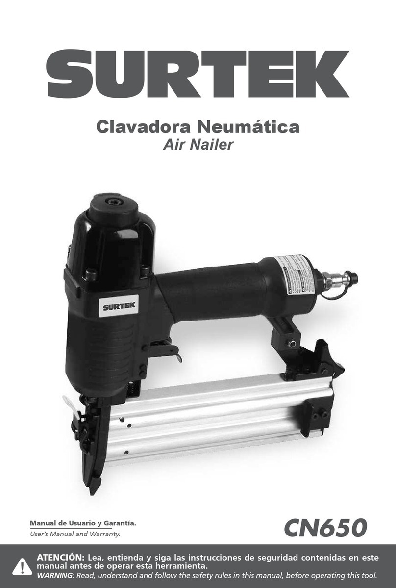
Emhart AutoSet 5 User manual

AutoSet®5 & 6
Operator & Maintenance
Manual

Contents
Introduction ___________________________________________________________________________ 2
Safety Instructions _____________________________________________________________________ 3
EC Declaration of Conformity_____________________________________________________________ 4
Specifications _________________________________________________________________________ 5
Tool Access ____________________________________________________________________________________ 5
Packaged Accessories____________________________________________________________________________ 6
Tool Requirements_______________________________________________________________________________ 6
Operation _____________________________________________________________________________ 7
Preparation for Operation _________________________________________________________________________ 7
Tool Operation __________________________________________________________________________________ 7
AIR FITTING OPERATION______________________________________________________________________ 7
NOSEPIECE SELECTION ______________________________________________________________________ 7
LOADING RIVET TAPE ________________________________________________________________________ 8
BASIC OPERATION___________________________________________________________________________ 8
VACUUM ADJUSTMENT _______________________________________________________________________ 8
RELOADING THE TOOL _______________________________________________________________________ 9
REMOVING PARTIALLY USED RIVET TAPE_______________________________________________________ 9
AutoSet®5 & 6 Diagram ________________________________________________________________ 10
Parts List ____________________________________________________________________________ 12
Maintenance__________________________________________________________________________ 14
Preventative Maintenance Schedule ________________________________________________________________ 14
Tool Maintenance ______________________________________________________________________________ 14
JAW REMOVAL AND CLEANING _______________________________________________________________ 14
JAW REPLACEMENT_________________________________________________________________________ 15
Tool Lubrication ________________________________________________________________________________ 16
INLINE LUBRICATION ________________________________________________________________________ 16
MANUAL LUBRICATION ______________________________________________________________________ 17
Oil Check _____________________________________________________________________________________ 17
Safety Data___________________________________________________________________________ 18
Troubleshooting ______________________________________________________________________ 19
Introduction
Thank you for choosing the Emhart Teknologies’ AutoSet®Riveting System.
The AutoSet®increases productivity by automatically feeding a rivet from a tape held within the magazine
directly to the nose of the tool, freeing one hand to hold and position the work piece.
Models Rivet Size Max. Body Length
North America [Europe]
AutoSet®5 1/8” (3.2mm) diameter rivets 46 [412]
(P/N: PA220-990) 5/32” (4.0mm) diameter rivets 56 [512]
AutoSet®6 3/16” (4.8mm) diameter rivets 66 [612]
(P/N: PA220-991) 1/8” (3.2mm) Large Flange diameter
rivets 46 [412]
AutoSet®tools must be used with genuine POPBrand Rivets on the tape as supplied by Emhart. Tool
performance cannot be guaranteed upon substitution of any other rivets or tape and may void warranty.
This manual contains basic AutoSet®tool maintenance instructions. For instructions on how to operate the
tool, please consult the AutoSet®“Operator’s Manual”.
Page 2 Emhart Teknologies - 50 Shelton Technology Center, Shelton CT 06484 - Tel. (203) 924-9341 - Fax (800) 225-5614

Safety Instructions
THIS MANUAL MUST BE CAREFULLY READ WITH PARTICULAR ATTENTION TO THE SAFETY
INSTRUCTIONS TO INSURE SAFE OPERATION, CORRECT FUNCTIONING, AND PROPER
SERVICING OF THE AUTOSET®TOOL
1. DO NOT use this tool in a manner other than that recommended by Emhart Teknologies.
2. DO NOT use equipment with this tool other than that recommended and supplied by Emhart
Teknologies.
3. This tool is NOT designed to be used in explosive environments.
4. Always wear eye protection. When using the tool both the operator and any person(s) in the
vicinity are required to wear eye protection to protect against injury.
5. DO NOT operate the tool in a hazardous environment.
6. Trained personnel must perform tool maintenance at the prescribed intervals to preserve
functionality and prevent damage.
7. DO NOT perform tool maintenance or service without first consulting the Maintenance
Manual or a trained technician.
8. Inspect tool and air hose for damage before use and repair as necessary.
9. Always disconnect the air supply when adjusting, servicing or removing any part of the tool.
10. When connecting the air supply to the tool or transporting the tool from place to place, avoid
touching the trigger to prevent accidental cycling of the tool.
11. Keep your fingers away from the front of the tool when connecting the air supply or setting
rivets.
12. Keep fingers away from the Nose Piston area when the Training Nose Adapter is installed to
avoid pinching them between the adapter and piston when the tool is cycled.
13. DO NOT point the tool at any person(s) or the operator.
14. DO NOT operate the tool if it is damaged.
15. DO NOT use the tool if the Mandrel Collection System cover/cap is open or damaged.
Expended mandrels may be ejected resulting in injuries.
16. DO NOT modify the tool in any way. In addition to voiding any applicable warranties,
unauthorized modifications can result in damage to the tool or physical injury to the user.
17. DO NOT look into the tool from the front or the back during use. Rivets or expended
mandrels may be ejected resulting in injury.
18. The operating air pressure shall not exceed 100 psi (6.9 bar).
19. If the Air Safety Alarm sounds, the maximum air pressure has been exceeded. Cease
operation of the tool immediately and disconnect the air supply. Regulate the air supply to
the recommended operating air pressure and resume tool operation.
20. If the Air Supply to the tool fails, cease operation of the tool and disconnect it from the Air
Supply.
21. Excessive contact with hydraulic fluid or lubricants should be avoided. Care should be taken
to wash thoroughly to prevent skin irritation. Use only Emhart recommended oils and
lubricants.
22. Take care to keep hair, fingers and loose clothing away from moving parts of the tool to
avoid entanglement and/or physical injury.
23. It is recommended that the operator wear hearing protection when using the tool.
Emhart Teknologies - 50 Shelton Technology Center, Shelton CT 06484 - Tel. (203) 924-9341 - Fax (800) 225-5614 Page 3

EC Declaration of Conformity
We, Emhart Teknologies
Tucker Fasteners Limited
Birmingham B42 1BP
England.
Declare that:
AutoSet®
Conforms to the following standards:
EN 292 part 1 and part 2 ISO prEN 15744
ISO 3744 EN 28662 - 1
ISO prEN 792 part 1 EN 12096
EN ISO 4871
Following the provisions of the Machine Directive 98/37/EEC which replaces Directive 89/392/EEC and its
amending Directives 91/368/EEC, 93/44/EEC and 93/68/EEC.
Signed:____________________________________
Eymard Chitty, Vice President, R&D
Birmingham
1st. November 2003
Page 4 Emhart Teknologies - 50 Shelton Technology Center, Shelton CT 06484 - Tel. (203) 924-9341 - Fax (800) 225-5614

Specifications
Overall Dimensions . . . . . . . . . . . . . . . . . . . . . . . . . . . . . . . . . . . . . . . . . . . . . . . . . . . . . . . . . . . . . . Height: 14.1” [358mm]
Length: 11.9” [303mm]
Width: 5.7” [46mm]
Weight . . . . . . . . . . . . . . . . . . . . . . . . . . . . . . . . . . . . . . . . . . . . . . . . . . . . . . . . . . . . . . . . . . . . . . . . Approx. 5lbs [~2.3 Kg]
Noise Level . . . . . . . . . . . . . . . . . . . . . . . . . . . . . . . . . . . . . . . . . . . . . . . . . . . . . . . . . . . . . . . . . . . . . . . . . . . 85 dB(A)**
Vibration Level . . . . . . . . . . . . . . . . . . . . . . . . . . . . . . . . . . . . . . . . . . . . . . . . . . . . . . . . . . . . . . . . . . 2.91 ft/s2 [0.89 m/s2]
Air Hose Length (Std.) . . . . . . . . . . . . . . . . . . . . . . . . . . . . . . . . . . . . . . . . . . . . . . . . . . . . . . Approx. 6ft [~2m], 5/16” I.D.
Tool Stroke . . . . . . . . . . . . . . . . . . . . . . . . . . . . . . . . . . . . . . . . . . . . . . . . . . . . . . . . . . . . . . . . . . . . . . . . . . 0.709” [18mm]
Pulling Force . . . . . . . . . . . . . . . . . . . . . . . . . . . . . . . . . . . . . . . . . . . . . . . . . . . . . . . . . . . . . . . . . . . . . . 1300 lbf [5782 N]
Cycle Time* . . . . . . . . . . . . . . . . . . . . . . . . . . . . . . . . . . . . . . . . . . . . . . . . . . . . . . . . . . . . . . . . . . . . . . Approx. 2 seconds
Rivets on Strip Capacity . . . . . . . . . . . . . . . . . . . . . . . . . . . . . . . . . . . . . . . . . . . . . . . . . . 1/8” [3.2mm]: 100 (AutoSet®5)
5/32” [4.0mm]: 80 (AutoSet®5)
3/16” [4.8mm]: 60 (AutoSet®6)
1/8” [3.2mm] Large Flange: 60 (AutoSet®6)
Mandrel Collection Capacity . . . . . . . . . . . . . . . . . . . . . . . . . . . . . . . . . . . . . . . . . . . . . . . . . . . . . . . . . . . 1 full Rivet Strip
* Note: Cycle time is determined by setting rivets in air.
** Note: It is recommended that the operator wear hearing protection when using the tool.
Tool Access
Note: If the Training Nose Adapter is installed, the Front-End Tool Access will be reduced.
Figure 1: Tool Envelope and Front-End Nosepiece access.
Emhart Teknologies - 50 Shelton Technology Center, Shelton CT 06484 - Tel. (203) 924-9341 - Fax (800) 225-5614 Page 5

Packaged Accessories
Part No. Item Qty Part No. Item Qty
DP220-155 Oil Fill Bottle (empty) 1 DP220-070 Pipe Spanner 1
DP220-074 Screwdriver 1 DP220-071 T-Wrench 1
DP220-165 Maintenance Tube 1 DP220-623 Jaw Setting Jig (2-pc) 1
DP220-073 14mm Flat Wrench 1 DP220-154 2.5mm Hex Key 1
DP220-072 15mm Flat Wrench 1 DP220-153 5mm Hex Key 1
DP220-502 5-size Nosepiece (AutoSet®5 only) 1 P444 Maintenance Manual 1
DP220-636 Air Hose Assembly 1 FG2177 Warranty Card 1
DP220-075 Training Nose Adaptor* 1
* Note: An optional Training Nose Adaptor is shipped with the
AutoSet®tool (Fig. 2). The Training Nose Adaptor may be
installed to prevent accidental tool and/or application damage
due to the cycling motion of the Nose Piston until the
operator becomes familiar with the tool operation.
! When the Training Nose Adapter is installed, a
pinch point is created between the Nose Piston
and Training Nose Adapter !
TRAINING NOSE ADAPTER
ATTACHMENT SCREWS
W
Figure 2: Training Nose Adapter
Tool Requirements
Air Supply* . . . . . . . . . . . . . . . . . . . . . . . . . . . . . . . . . . . . . . . . . . . . . . . . . . . . 85-100 PSI (5.8-6.9 Bar) filtered, lubricated
Air Flow . . . . . . . . . . . . . . . . . . . . . . . . . . . . . . . . . . . . . . . . . . . . . . . . . . . . . . . . . . . . . . . . . . 6 scfm (150 l/min) Minimum
Hydraulic Oil** . . . . . . . . . . . . . . . . . . . . . . . . . . . . . . . . . . . . . . . . . . . . . . . . . . Shell Spindle Oil #22 or Emhart equivalent
Jaw Lubricant**. . . . . . . . . . . . . . . . . . . . . . . . . . . . . . . . . . . . . . . . . . . . . . . . . Lithium Grease w/ Molybdenum Disulfide
Seal Lubricant**. . . . . . . . . . . . . . . . . . . . . . . . . . . . . . . . . . . . . . . . . . . . . . . . . Shell Spindle Oil #22 or Emhart equivalent
(See the Safety Data section for Emhart equivalents.)
* Note: It is recommended that a combination
Filter/Regulator/Lubricator (DP220-804) be installed in the air
supply to the tool (Fig. 3). If an Inline Lubricator is not
installed, then tool lubrication must be performed as indicated
in the “Maintenance” section.
** Note: Lubricant Safety information is located in the “Safety
Data” section.
LUBRICATOR
FILTER
REGULATOR
AIR SUPPLY
Figure 3: In-line Lubrication set-up.
Page 6 Emhart Teknologies - 50 Shelton Technology Center, Shelton CT 06484 - Tel. (203) 924-9341 - Fax (800) 225-5614

Operation
Preparation for Operation
Before operating the tool check the following:
Inspect the tool for damage and/or signs of wear and replace or repair parts as required. DO NOT use the tool if damaged.
If using inline lubrication, check the adjustment on the Lubricator and make sure there is an adequate oil supply. The Lubricator
should be as close to the tool as possible.
If using manual lubrication, check to see if the tool needs to be lubricated as prescribed in the Maintenance Manual.
Check the Air supply pressure and make sure it is between 85-100 PSI (5.8-6.9 Bar).
Check the tool air hose for wear or damage and replace if necessary.
If suspending the tool via a Tool Balancer or other device, check to make sure the tool is secure.
Check that the proper Nosepiece is installed for the rivet to be used.
Empty the Mandrel Collection System of all spent mandrels.
Tool Operation
AIR FITTING OPERATION
The air fitting supplied with the AutoSet®tools has an On/Off
flow valve built into it. To operate the valve, do the following:
1. Push the female Quick-connect hose fitting over the male
fitting on the AutoSet®tool. When fully connected you will
see a blue Indicator Ring (Fig. 4).
2. To turn on the air supply to the tool, slide the Sleeve
toward the blue Indicator Ring.
3. To lock the fitting so that the air does not accidentally get
shut off, twist the Collar and Sleeve so that the Locking
Arrows line up.
LOCK
AIR SUPPLY OFF
AIR SUPPLY ON
SLEEVE BLUE INDICATOR RING
LOCK ARROWS
COLLAR
Figure 4: Tool Air Supply fitting.
NOSEPIECE SELECTION
Open End Rivets (All Materials) &
Closed End Rivets (Al/Al) Closed End Rivets
(Al/St)
Rivet Size Domed Countersunk Domed Countersunk
1/8” (3.2mm) diameter rivets DP220-501 DP220-527 DP220-500 DP220-525
5/32” (4mm) diameter rivets DP220-502 DP220-528 DP220-501 DP220-527
3/16” (4.8mm) diameter rivets DP220-503 DP220-529 N/A N/A
Al / Al = Aluminum Body and Mandrel Al / St = Aluminum Body and Steel Mandrel
Emhart Teknologies - 50 Shelton Technology Center, Shelton CT 06484 - Tel. (203) 924-9341 - Fax (800) 225-5614 Page 7

Tool Operation – Cont’d
LOADING RIVET TAPE
1. Turn off the air supply to the tool.
2. Open the Magazine on the AutoSet®tool.
3. Locate the Plate Spring on the Indexing Assembly.
4. Insert the leading edge of the Rivet Tape underneath the
Plate Spring so that the 1st “Rung” of the tape is past the
Pawl (Fig. 5). Take care not to push a rivet out of the tape.
Note: The mandrel side of the rivet should be facing
towards the rear of the tool.
5. Coil the Rivet Tape and place it in the Magazine.
6. Close the Magazine making sure the Magazine Latch is
completely engaged.
PLATE SPRING
PAWL
"1st RUNG"
TOOL FRONT
NOSE PISTON
Figure 5: Loading Rivet Tape
BASIC OPERATION
Before operating the tool, check the tool for damaged or worn
parts and fix or replace as necessary. Also, make sure the tool
is properly lubricated.
1. Check that the air supply is set to the proper pressure
range for the tool: 85-100 PSI (5.8-6.9 Bar).
2. Connect the air supply to the tool.
3. Turn on the air supply by sliding the valve sleeve towards
the tool (see the “AIR FITTING OPERATION” section).
!When turning the air supply on be sure to keep your
hands away from the Nose Piston as the Nose Piston
may actuate!
4. Pull the trigger to index the Rivet Tape and feed a rivet into
the Nosepiece.
Figure 6: Air Supply connection.
VACUUM ADJUSTMENT
When feeding rivets through the tool it may be necessary to
adjust the vacuum level of the MCS system to ensure proper
feeding and holding of the rivet and proper spent mandrel
collection.
1. To adjust the vacuum, locate the Vacuum Adjustment
flitting on the side of the tool near the MCS system.
2. Rotate the Adjustment Knob and adjust the vacuum as
necessary to hold the rivet in the Nosepiece and collect
the spent mandrels.
3. Once the vacuum level has been set, rotate the Lock-nut
on the Vacuum Adjustment fitting to prevent the vacuum
level from changing.
4. Begin setting rivets in the application.
LOCK-NUT
ADJUSTMENT KNOB
Figure 7: Vacuum adjustment fitting.
Page 8 Emhart Teknologies - 50 Shelton Technology Center, Shelton CT 06484 - Tel. (203) 924-9341 - Fax (800) 225-5614

Tool Operation – Cont’d
RELOADING THE TOOL
Once all of the rivets on the Rivet Tape are used, the Rivet
Tape needs to be removed to load the next coil.
1. With the air supply on, pull the Trigger on the tool and hold
it so that the Nose Piston remains in the back position.
2. While holding the Trigger, turn off the air supply by sliding
the Valve Sleeve on the Air Hose away from the tool.
3. Firmly grasp the empty Rivet Tape and pull it away from
the tool as shown in Figure 8.
4. Empty the spent mandrels from the MCS chamber.
5. Turn on the air supply so that the Nose Piston returns to
the forward position.
!Keep your hands away from the Nose Piston when it
cycles forward !
6. Reload the tool as described in the “LOADING RIVET
TAPE” section.
Figure 8: Rivet Tape removal.
REMOVING PARTIALLY USED RIVET TAPE
If the situation arises where the operator desires to switch to a
different rivet while there are still rivets in the tool, the Rivet
Tape can be removed as follows:
1. Turn off the air supply to the tool and open the Magazine.
2. Remove 4 or 5 rivets from the Tape that are closest to the
Nose Piston.
3. With a pair of scissors, cut the tape at the point where you
removed the rivets.
4. Remove the remaining rivets from the Magazine and
remove the spent Rivet Tape as described in the
“RELOADING THE TOOL” section.
5. Reload the tool as described in the “LOADING RIVET
TAPE” section.
Emhart Teknologies - 50 Shelton Technology Center, Shelton CT 06484 - Tel. (203) 924-9341 - Fax (800) 225-5614 Page 9

AutoSet®5 & 6 Diagram
Note: Item Numbers in Brackets [ ] are for the AutoSet®6 tool.
AutoSet 6 Indexer Assembly
Page 10 Emhart Teknologies - 50 Shelton Technology Center, Shelton CT 06484 - Tel. (203) 924-9341 - Fax (800) 225-5614

Emhart Teknologies - 50 Shelton Technology Center, Shelton CT 06484 - Tel. (203) 924-9341 - Fax (800) 225-5614 Page 11

Page 12 Emhart Teknologies - 50 Shelton Technology Center, Shelton CT 06484 - Tel. (203) 924-9341 - Fax (800) 225-5614
Parts List
No. Emhart P/N Description AS 5 AS 6
85 DP220-085 O-ring P18 2 2
88 DP220-088 Penta Seal, 15mm dia. 1 1
89 DP220-089 Penta Seal, 24mm dia. 1 1
90 DP220-090 Air Seal, 41.5mm dia. 2 2
92 DP220-092 DU Bushing 1 1
94 DP220-094 DU Bushing 4 4
95 DP220-095 O-ring 1 1
96 DP220-096 O-ring 1 1
97 DP220-097 E Ring - Magazine pin 2 2
98 DP220-098 E Ring - MCS Cap Shaft 5 5
99 DP220-099 C Ring - Trigger 1 1
101 DP220-101 Fill Plug 1 1
102 DP220-102 Socket Head Cap Screw - SUS 2 2
103 DP220-103 Hex bolt M5 x 16 SHSC, SS 1 1
104 DP220-104 Socket Head Cap Screw - SUS 4 4
105 DP220-105 Torx Head Cap Screw - SUS 2 2
106 DP220-106 Button Head Cap Screw - SUS 4 4
107 DP220-107 Cross-recessed PH Mach Screw 2 2
108 DP220-108 Cross-recessed PH Tap Screw 1 1
109 DP220-109 Cross-recessed PH Mach Screw 1 1
110 DP220-110 Cross-recessed PH Mach Screw 1 1
111 DP220-111 Hexagonal Bolt - SUS 1 1
112 DP220-112 Socket Head Cap Screw - SUS 1 1
113 DP220-113 Socket Set Screw 1 1
114 DP220-114 Socket Set Screw 2 2
115 DP220-115 Socket Head Cap Screw - Metric 2 2
117 DP220-117 O-RING - 29.7 X 2.4 X-SECT 1 1
118 DP220-118 Push-to-connect, Male 6 mm 4 4
119 DP220-119 Push-to-connect, Male 4 mm 1 1
120 DP220-120 Elbow fitting, 6 mm 2 2
121 DP220-121 Barb elbow 360, 6 mm 2 2
122 DP220-122 Barb elbow 360, 4 mm 1 1
123 DP220-123 Push-to-connect Male 6 mm 1 1
124 DP220-124 Nose piston hydraulic seal 1 1
125 DP220-125 Wear ring 2 2
126 DP220-126 Jaw case piston hydraulic seal 1 1
129 DP220-129 Cross-recessed PH Mach Screw 1 1
130 DP220-130 O-ring 1 1
132 DP220-132 Socket Head Cap Screw - SUS 4 4
134 DP220-134 Button Head Cap Screw - SUS 2 -
135 DP220-135 O-ring P20 2 -
136 DP220-136 Indexer Exhaust Gasket 1 1
137 DP220-137 Socket Head Cap Screw - SUS 4 -
139 DP220-139 Socket Head Cap Screw - SUS 2 2
140 DP220-140 Valve Assembly 1 1
141 DP220-141 Socket Head Cap Screw - SUS 2 2
142 DP220-142 Socket Head Cap Screw - SUS 3 3
143 DP220-143 E Ring - Horizontal hanger 2 2
144 DP220-144 Magazine foot 2 2
145 DP220-145 Washer - M3 2 2
146 DP220-146 Socket Head Cap Screw - SUS 2 2
162 DP220-162 Magazine Latch 1 1
163 DP220-163 Magazine Latch Pin 1 1
164 DP220-164 Magazine Latch Spring 1 1
No. Emhart P/N Description AS 5 AS 6
3 DP220-003 Trigger Shaft 1 1
4 DP220-004 Trigger Cover 1 1
5 DP220-005 Trigger Shaft Sleeve 1 1
10 DP220-010 High Pressure Piston 1 1
11 DP220-011 Valve Block - 5 1 -
15 DP220-015 Jaw Pusher Spring 1 1
16 DP220-016 Trigger Spring 1 1
18 DP220-018 Tool Hanger - Horizontal 1 1
19 DP220-019 Grip Cover 1 1
20 DP220-020 Relief Valve Spring 1 1
21 DP220-021 Relief Valve 1 1
22 DP220-022 Pilot Piston Trigger 1 1
23 DP220-023 Slide Guide 1 1
24 DP220-024 Centering Finger 2 2
25 DP220-025 Centering Finger Shaft 2 2
27 DP220-027 Trigger 1 1
29 DP220-029 Centering Spring 2 2
30 DP220-030 Alarm Valve screw 1 1
31 DP220-031 Air Valve Supply Tube 1 1
32 DP220-032 Air Supply Tube 1 1
33 DP220-033 Air Chamber Supply Tube 1 1
34 DP220-034 Piston Retract Supply Tube 1 1
35 DP220-035 Return Supply Tube 1 1
36 DP220-036 Air Valve Shuttle Supply Tube 1 1
37 DP220-037 Mandrel Deflector 1 1
39 DP220-039 Cap - MCS 1 1
40 DP220-040 Latch box 1 1
41 DP220-041 Cap Shaft - MCS 1 1
42 DP220-042 Latch Shaft - MCS 1 1
43 DP220-043 Latch Spring Receiver - MCS 1 1
44 DP220-044 Latch - MCS 1 1
45 DP220-045 Magazine Clear Cover - 5 1 -
46 DP220-046 Magazine Base - 5&6 1 1
47 DP220-047 Cover Plate 1 -
48 DP220-048 Indexer Exhaust Bolt 1 1
49 DP220-049 Latch Spring - MCS 1 1
50 DP220-050 Magazine pin 1 1
51 DP220-051 Centering Base - 5 1 -
52 DP220-052 Plate Spring - 5 1 -
53 DP220-053 Plate Spring Support - 5 1 -
54 DP220-054 Indexer Piston A - 5 1 -
55 DP220-055 Indexer Piston B - 5 1 -
56 DP220-056 Pawl - 5 1 -
57 DP220-057 Indexer Cap - 5 1 -
58 DP220-058 Indexer Spring - 5 2 -
59 DP220-059 Indexer Buffer Spring - 5 1 -
61 DP220-061 Jaw Pusher - 5 size 1 -
62 DP220-062 Slide Pipe - 5 size 1 -
75 DP220-075 Training Nose Adaptor 1 1
78 DP220-078 O-ring - S40 2 2
79 DP220-079 O-ring JASO3067 1 1
80 DP220-080 O-ring - S40 5 5
81 DP220-081 O-ring P10 - Fill screw 1 1
82 DP220-082 O-ring P6 2 2
83 DP220-083 O-ring S2 3 3

No. Emhart P/N Description AS 5 AS 6
174 DP220-174 Torx Head Cap Screw - Metric 2 2
176 DP220-176 Barb elbow 360, 6 mm 1 1
182 DP220-182
Filter Holder (upgrade) 1 1
183 DP220-183
Filter Case (upgrade) 1 1
184 DP220-184
Cotton Ball (1 pc) 2 2
185 DP220-185
O-ring - Filter Holder (upgrade) 1 1
201 DP220-201 Plate Spring - 6 - 1
202 DP220-202 Pawl - 6 - 1
204 DP220-204 Indexer Spring - 6 - 1
205 DP220-205 Centering Base - 6 - 1
206 DP220-206 Indexer Piston A - 6 - 1
207 DP220-207 Indexer Piston B - 6 - 1
208 DP220-208 Indexer Cover Plate - 6 - 1
209 DP220-209 Indexer Buffer Spring - 6 - 1
210 DP220-210 Plate Spring Support - 6 - 1
211 DP220-211 Magazine Clear Cover - 6 - 1
214 DP220-214 Valve Block - 6 - 1
215 DP220-215 Jaw Pusher - 6 size - 1
216 DP220-216 Slide Pipe - 6 size - 1
220 DP220-220 O-ring P16 - 1
402 DP220-402 Vacuum Tube Elbow Fitting 2 2
403 DP220-403 Vacuum Adjustment Fitting 1 1
404 DP220-404 Vacuum Tube - long 1 1
405 DP220-405 Vacuum Tube - short 1 1
406 DP220-406 Cable tie 2 2
407 DP220-407 Air Fitting - Male 1 1
414 DP220-414 Wear Ring Indexer Piston A - 5 1 -
416 DP220-416 Wear Ring Indexer Piston A - 6 - 3
421 DP220-421 Tube Bracket 1 1
618 DP220-618 Jaw Set - 5 ( 3 piece set ) 1 -
619 DP220-619 Jaw Set - 6 ( 3 piece set ) - 1
Nosepieces
500 DP220-500 Nosepiece 1/8" Close End Acc -
501 DP220-501
Nos
5/32"
epiece 1/8" Open End &
Close End 1 -
502 DP220-502 Nosepiece 5/32" Open End 1 -
503 DP220-503
Nosepie
End ce 3/16" Open & Close - 1
525 DP220-525
Nos
Coun
epiece 1/8" Close End
tersunk Acc -
527 DP220-527
Nos
5/32"
epiece 1/8" Open End &
Close End Countersunk Acc Acc
528 DP220-528
Nos
Coun
epiece 5/32" Open End
tersunk Acc -
529 DP220-529
Nosepie
End Counter
ce 3/16" Open & Close
sunk - Acc
No. Emhart P/N Description AS 5 AS 6
Assemblies
607 DP220-607 Jaw case piston Assy. w/Seals
Includes: -002,-006,-084,-090,-
117,-125,-126 Acc Acc
611 DP220-611 Nose piston Assy. w/Seals
Includes: -001,-088,-090,-093,-
124,-125 Acc Acc
616 DP220-616 Magazine Assembly - 5
Incl.: -046,-050,-097 (x2),-144
(x2),-162,-163,-164,-045 Acc Acc
617 DP220-617 Magazine Assembly - 6
Incl.: -046,-050,-097 (x2),-144
(x2),-162,-163,-164,-211 Acc Acc
636 DP220-636 Air Hose Assembly 11
638 DP220-638 Nose Piston Assembly
Includes: -001,-093 11
639 DP220-639 Jaw Case Piston Assembly
Includes: -002,-006,-084 11
640 DP220-640 Trigger Valve Assembly
Includes: -012,-127,-133 (x3) 11
641 DP220-641 Indexer Housing Assembly - 5
Includes: -092,-133 (x5),-138,-
060 1-
642 DP220-642 Indexer Housing Assembly - 6
Includes: -092,-133 (x6),-138,-
203 -1
643 DP220-643 Mandrel Collector Housing Assy
Includes: -151,-013,-014,-028,-
116,-133 (x2) 11
644 DP220-644 POP Handle Assembly
Includes: -177,-091,-127,-128 11
646 DP220-646 Intensifier Chamber Assembly
Includes: -179,-133 11
Accessories
409 DP220-409 Inline Hook Acc Acc
410 DP220-410 E-Ring - Inline hook Acc Acc
Lubricants
POP DP220-804 Inline Oiler Kit (Filter, Re
g
ulator,
Lub.) Acc Acc
POP DP220-806 Hydraulic oil, 1 QT container Acc Acc
POP DP220-810 Moly Grease, 2.5 oz jar Acc Acc
Seal Kit
POP DP220-811 AutoSet™ Seal kit Acc Acc
Includes: DP220-081, -085 (x2), -087, -088, -089, 090 (x2) , -117, -124, -
126.
Nosepiece Selection Open End Rivets (All Materials) &
Closed End Rivets (Al/Al) Closed End Rivets
(Al/St)
Rivet Size Domed Countersunk Domed Countersunk
1/8” (3.2mm) diameter rivets DP220-501 DP220-527 DP220-500 DP220-525
5/32” (4mm) diameter rivets DP220-502 DP220-528 DP220-501 DP220-527
3/16” (4.8mm) diameter rivets DP220-503 DP220-529 N/A N/A
Al/Al = Aluminum Body and Aluminum Mandrel; Al/St = Aluminum Body and Steel Mandrel
Emhart Teknologies - 50 Shelton Technology Center, Shelton CT 06484 - Tel. (203) 924-9341 - Fax (800) 225-5614 Page 13

Maintenance
Preventative Maintenance Schedule
Item Freq Action
MCS Container 1x per Rivet Strip Empty MCS Container.
Jaw and Nose Piston
Front End Jaw area
Cleaning
1x per Shift or
5k - 8k Cycles
Remove Nosepiece and Jaws; clean and lubricate.
Clean debris from inside Nose Piston – step11 (See “Jaw removal and
cleaning” )
Front-End Maintenance 1x per week or
20k Cycles Clean debris off of the outside of Indexing Assembly.
Lubrication – Manual 1x per week or
20k Cycles Add 1 drop Hydraulic Oil* in Air Fitting and 1 drop Hydraulic Oil* on Nose
Piston.
Lubrication – Inline 1 x per week Check tool for proper lubrication (See “Lubrication Indicators”)
Oil Level Check 1x per week or
20k Cycles Remove fill plug and check the oil level. Replenish if necessary.
Muffler 1x per week or
20k Cycles Remove filter case and check wear of filter material. Replace if
necessary.
* Note: Use only Emhart specified greases and lubricants as indicated in the “Tool Requirements” section.
Tool Maintenance
JAW REMOVAL AND CLEANING
For optimal tool performance, remove the Jaws and clean at
regular intervals per the “Preventative Maintenance Schedule”.
1. Remove all rivets and spent mandrels from the tool.
2. Shut off air supply via the hose fitting at the bottom of the
tool (Fig. 9).
3. Remove the nosepiece using the 14mm and 15mm Flat
Wrenches supplied with the tool (Fig. 9).
4. Open the MCS Cap and with the Screwdriver and
Maintenance Tube, remove the slide guide (Fig. 10).
5. Turn on the air supply and pull the Trigger so that the
Nose Piston travels to the back position.
Figure 9: Shut-off air and remove Nosepiece.
6. While holding the Trigger, shut off the air supply so that
the Nose Piston remains in the back position.
!Note: For safety, disconnect the air hose from the
tool!
7. Using the Pipe Spanner to keep the Jaw Case Piston from
rotating, remove the Slide Pipe with the Screwdriver and
Maintenance Tube (Fig. 11).
Note: The front of the Pipe Spanner aligns with a boss
inside the Jaw Case Piston.
SCREWDRIVER
SLIDE GUIDE
MAINTENANCE TUBE
Figure 10: Slide Guide removal.
Page 14 Emhart Teknologies - 50 Shelton Technology Center, Shelton CT 06484 - Tel. (203) 924-9341 - Fax (800) 225-5614

Tool Maintenance – Cont’d
JAW REMOVAL AND CLEANING – CONT’D
8. Turn the tool upside down and remove the Slide Pipe, Jaw
Pusher Spring, Jaw Pusher and 3-piece Jaw set (Fig. 13).
Note: If the Jaws stick to the inside of the Jaw Case
Piston, use the T-Wrench to push the Jaws out from the
front of the tool.
9. Clean out debris in the MCS area and in the back of the
Jaw case with a rag and air hose to blow out the tool.
10. Close the MCS Cap and reconnect the air hose to the tool.
11. Turn on the air supply allowing the Nose Piston to cycle
forward.
SCREWDRIVER
PIPE
SPANNER
MAINTENANCE
TUBE
Figure 11: Slide Pipe removal.
12. Pull the trigger and then quickly shut-off the air supply
causing the Jaw Case Piston to separate from the Nose
piston.
13. Disconnect the air supply and thoroughly clean any debris
from the Front-End Jaw Area (fig. 12). Be sure to clean
any debris from in between the Jaw Case Piston and Nose
Piston.
14. Blow air through the tool to remove any loose debris and
wipe clean again.
15. Clean the 3-piece Jaws and Jaw Pusher and remove any
debris from the Jaw Spring and Slide Pipe (Fig.13). Check
each part for wear or damage and replace if necessary.
NOSE PISTON
Figure 12: Front-End Jaw area.
JAWS JAW PUSHER JAW SPRING SLIDE PIPE
Figure 13: Jaw assembly.
JAW REPLACEMENT
To insert a cleaned or a new Jaw assembly into the tool do the
following:
1. Turn on the air supply to the tool and pull the Trigger so
that the Nose Piston travels to the back position.
2. While holding the Trigger, shut off the air supply so that
the Nose Piston remains in the back position.
!Note: For safety, disconnect the air hose from the
tool!
3. Place the Jaws into the brass Jaw Holder at the end of the
Plunger with the back of the Jaws facing out (Fig. 14).
APPLY GREASE
HERE
JAW SETTING JIG
JAW HOLDER
PLUNGER
Figure 14: Jaw setting jig.
4. Using the Jaw Holder, insert the Jaws into the chamfered
end of the Jaw Setting Jig and apply Jaw Grease (use
Emhart specified Jaw Grease (DP220-810) only) to the
outside face of each Jaw (Fig. 14).
5. Insert the Jaw Setting Jig into the back of the tool and
push in until it touches the front of the Jaw Case Piston
(Fig. 15).
6. Holding the jig like a syringe, depress the Jaw Holder,
pushing the Jaws out of the tube and setting them in place
in the Jaw Case Piston (Fig. 15).
JAW SETTING JIG
PLUNGER
Figure 15: Jaw insertion.
Emhart Teknologies - 50 Shelton Technology Center, Shelton CT 06484 - Tel. (203) 924-9341 - Fax (800) 225-5614 Page 15

Tool Maintenance – Cont’d
JAW REPLACEMENT – CONT’D
7. Re-insert the Jaw Pusher, Jaw Spring and Slide Pipe
using the Pipe Spanner and Screw Driver with
Maintenance Tube (Fig. 16).
8. Tighten the Slide Pipe to a torque of 32.7 in-lb (3.7 N-m).
9. Re-connect the air hose and turn on the air supply allowing
the Nose Piston to cycle to the forward position.
!Note: When turning on the air supply, keep your
hands away from the Nose Piston area!
Figure 16: Jaw Assembly re-insertion.
10. Once the Nose Piston is in the forward position, shut off
the air supply and check to see that the 3-piece Jaws are
seated properly. If not, repeat steps 3 through 9.
11. Attach the Slide Guide to the Maintenance Tube on the
Screwdriver and insert into the tool and tighten (Fig. 17).
12. Close the MCS door and install the desired nosepiece.
Figure 17: Re-assemble Slide Guide.
Tool Lubrication
In order for the tool to operate properly and achieve optimal performance it must be lubricated through the air supply. If the tool is allowed
to cycle without lubrication then the performance of the tool will begin to decrease due to premature o-ring wear. The tool should be
lubricated using the Hydraulic Oil (Emhart P/N: DP220-806) listed in the Tool Requirements section only. This is the same oil used in the
hydraulic system. There are two methods of lubrication:
1. Inline Lubrication (Recommended)
2. Manual Lubrication
INLINE LUBRICATION
Inline lubrication involves adding oil to the tool air supplied to
the tool via an Air Lubricator attached inline with the air supply
to the tool. It is recommended that a Filter/Regulator be used
along with the Lubricator. When using Inline Lubrication, the
Lubricator setup should be placed as close to the tool as
possible. A recommended Filter/Regulator/Lubricator setup is
listed in the “Spare Parts” section.
INITIAL SET-UP:
1. To setup the inline lubricator, fill the lubricator with oil
according to the Lubricator instructions and set it to the
minimum setting.
2. Run the tool in production for 1 to 2 days, checking the
“Lubrication Indicators” periodically for signs of improper
lubrication (See “Lubrication Indicators”).
3. Adjust as required.
Page 16 Emhart Teknologies - 50 Shelton Technology Center, Shelton CT 06484 - Tel. (203) 924-9341 - Fax (800) 225-5614

Tool Lubrication – Cont’d
MANUAL LUBRICATION
Manual Lubrication is a simple method recommended for low
volume tool use where there is a qualified technician available
to service the tool. The manual lubrication process is as
follows:
1. Add one drop of Hydraulic Oil* inside the air fitting on the
tool (Fig. 18).
2. Add one drop of Hydraulic Oil* to the O.D. of the Nose
Piston (Fig. 18).
3. Cycle the tool 4-5 times to circulate the oil and wipe off any
excess.
4. Check the tool periodically for signs of improper lubrication
(See “LUBRICATION INDICATORS”).
*Note: Use only Emhart specified Hydraulic Oil.
Note: When manually lubricating the tool, DO NOT add
oil or grease to the Indexing Mechanism as this may
cause the mechanism to gum up with debris and not
function properly.
Figure 18: Manual Lubrication.
LUBRICATION INDICATORS
Indication Remedy
Not Enough
Lubrication
a. Dry, black film present on the Nose Piston.
b. Tool makes unusual noises when cycled. Inline Method: Increase the oil drip setting on the
lubricator.
Manual Method: Increase the lubrication frequency.
Too Much
Lubrication
a. Muffler filter material turns yellow with oil. Inline Method: Reduce the oil drip setting on the
lubricator or go to a smaller lubricator if necessary.
Manual Method: Reduce the lubrication frequency.
Oil Check
OIL LEVEL CHECK
For optimal tool performance, the oil level of the tool should be
checked at regular intervals per the Preventative Maintenance
schedule.
1. To check the oil level, turn off and disconnect the air
supply from the tool.
2. Remove the Fill Plug on the back of the tool handle, taking
care not to damage the Fill Plug O-ring.
3. Place your thumb over the oil port and gently rock the tool
to release any potential air trapped in the tool through the
Fill Plug port (Fig. 19).
4. Remove your thumb and check the oil level.
5. If the level is low, add the specified Hydraulic Oil so that
the oil covers more than ½ of the threads in the Fill Port
(Fig. 19).
Note: Use only Emhart specified Hydraulic Oil (see the
“Specifications” section).
6. Repeat steps 1 thru 5 until the oil level is adequate.
7. Replace the Fill Plug taking care not to damage the Fill
Plug O-ring.
OIL FILL LEVEL
Figure 19: Oil Level check.
Emhart Teknologies - 50 Shelton Technology Center, Shelton CT 06484 - Tel. (203) 924-9341 - Fax (800) 225-5614 Page 17

Safety Data
MOLY GREASE (Emhart P/N: DP220-810)
Manufacturer:
T.S. Moly-Lubricants, Inc., Houston, TX
Emergency: (713)671-2676
MSDS Number: TS-122 Lithium EP-2 Moly Poly Grease
First Aid:
SKIN:
Prolonged or repeated skin contact with this product tends to
remove skin oils, possibly leading to irritation and dermatitis.
No chronic health problems known.
INGESTION:
May cause irritation and gastrointestinal discomfort consisting of
nausea, vomiting, lethargy and/or diarrhea.
EYES:
Flush eyes with plenty of water for several minutes. Get
medical attention if eye irritation persists.
Fire:
FLASH POINT: 450F/232C
Use water to cool containers exposed to fire. For fires in
enclosed areas, firefighters should use self-contained breathing
apparatus. Avoid fumes or burning product.
Environment:
WASTE DISPOSAL:
Because material uses, transformations, mixtures, processes,
etc. may affect classification; it is the responsibility of the user to
determine the method of disposal according to the latest EPA,
state and local regulations
SPILLAGE:
Recover free product. Add sand, earth, or some other suitable
adsorbent. Keep product out of sewers and watercourses by
diking or impounding.
Handling/ Storage:
Store in cool dry area in original or equivalent container in
accordance with all applicable regulations. Do not apply high
heat or flame to container.
Emhart Approved Equivalents:
None
MOBILVELOCITE OIL #10 (Emhart P/N: DP220-806)
Manufacturer:
EXXONMOBIL Oil Corp., Fairfax, VA
Emergency: (609)737-4411 (call collect)
MSDS Number: 600684-00
First Aid:
SKIN:
Remove contaminated clothing and shoes and wipe excess
from skin. Flush skin with water, and then wash with soap and
water. If irritation occurs, get medical attention. Do not reuse
clothing until cleaned.
INGESTION:
Do not induce vomiting. In general, no treatment is necessary
unless large quantities of product are ingested. However, get
medical attention.
EYES:
Flush with water. If irritation occurs, get medical attention.
Fire:
FLASH POINT: 345 F/174 C
Material will float and can be re-ignited on the surface of water.
Use water fog, ‘alcohol foam’, dry chemical or carbon dioxide
(CO2) to extinguish flames. Do not use a direct stream of water.
Environment:
WASTE DISPOSAL:
Because material uses, transformations, mixtures, processes,
etc. may affect classification; it is the responsibility of the user to
determine the method of disposal according to the latest EPA,
state and local regulations.
SPILLAGE:
Soak up residue with an absorbent such as clay, sand or other
suitable material. Place in a non-leaking container and seal
tightly for proper disposal. Report spills/releases as required to
appropriate authorities.
Handling:
Wash with soap and water before eating, drinking, smoking,
applying cosmetics, or using toilet. Properly dispose of leather
articles such as shoes or belts that cannot be decontaminated.
Use in a well ventilated area. High pressure injection under the
skin may occur due to the rupture of pressurized lines. Always
seek medical attention.
Storage:
Keep containers closed when not in use. Do not store in open
or unlabelled containers. Store away from strong oxidizing
agents and combustible materials. Do not store near heat,
sparks, flame or strong oxidants.
Emhart Approved Equivalents:
Shell Spindle Oil #22
Shell Tellus Oil #22
Please refer to the actual MSDS sheets of the materials for complete safety and handling information. These can be obtained from Emhart
Teknologies, Inc. or directly from the manufacturer.
Page 18 Emhart Teknologies - 50 Shelton Technology Center, Shelton CT 06484 - Tel. (203) 924-9341 - Fax (800) 225-5614

Troubleshooting
For any other issues, please contact your Distributor.
Symptom Probable Cause Remedy
MCS chamber Full. Empty MCS Chamber of spent mandrels.
The Slide Guide and/or the Slide Pipe have
come loose.
Examine the parts for damage and reattach
per the Jaw Replacement instructions in the
“Tool Maintenance” section
Nose Piston stops part of the way back.
Debris built up between the Jaw case and
the Nose Piston Clean Front End Jaw area. Follow step 10-14
of “Jaw removal and cleaning” section.
Rivets are not being held in Nosepiece. Tool Vacuum out of adjustment. Re-adjust Tool Vacuum.
MCS door is open or not closed tight. Close MCS door. Adjust the latch box
(DP220-182) to ensure the door sealed
close.
Muffler is clogged. Clean or replace filter material as necessary.
Rivet does not set in application. Air pressure is too low. Adjust air pressure to 85-100 psi (5.8-6.9
bar).
Worn or dirty Jaws. Service Front-End and Jaws.
Rivet breakload is too high. Contact your Distributor.
Oil level dropped or air in oil. Perform Oil Level check.
Mandrel jammed in Nose Piston area. Wrong Nosepiece. Use nosepiece that is compatible with rivet
being used.
Dirt or debris between Nose Piston and Jaw
Case. Service Front-End and Jaws.
Rivet fails to insert into Nosepiece. Wrong Nosepiece. Use Nosepiece compatible with rivet being
used.
Rivets not inserted properly in Rivet Tape. Check Rivet Tape, replace if damaged.
Dirt or debris between Nose Piston and Jaw
Case. Service Front-End and Jaws.
Air has accumulated in hydraulic chamber. Perform Oil Level check.
Feeding mechanism is out of alignment. Contact your Distributor.
Operating speed has dropped. Air pressure too low. Adjust air pressure to 85-100 psi (5.8-6.9
bar).
Tool not getting enough lubrication. Perform Manual Tool lubrication as described
in "Tool Lubrication" section.
Air has accumulated in hydraulic chamber. Perform Oil Level check.
Nose Piston rapidly moving back and forth. Trigger piston is at the air passage
changeover point. With air supply connected, pull Trigger for 3
seconds or more and release.
There is a loud noise in the air fitting area. The air pressure alarm device has been
activated. Check the air pressure and adjust to 85-100
psi (5.8-6.9 bar).
Emhart Teknologies - 50 Shelton Technology Center, Shelton CT 06484 - Tel. (203) 924-9341 - Fax (800) 225-5614 Page 19

AMERICAS
United States
Connecticut
50 Shelton Technology Center
P.O. Box 859
Shelton, CT 06484
USA
Tel. 203-924-9341
Fax. 800-225-5614
Canada
9870 boul. du Golf
Anjou, Québec H1J 2Y7
Canada
Tel. 514-351-0330
Fax. 514-351-0458
Brazil
Rua Ricardo Cavatton, 226 – LAPA
Sao Paulo, SP
Brazil
CEP 05038-110
Tel. +55-11-3871-6460
Fax +55-11-3611-3508
México
Bosque de Radiatas No 42
Bosques de las Lomas
05120 México, D.F.
Tel. +52-555-326-7100
Fax. +52-555-326-7141
EUROPE
Denmark
Farverland 1B
DK-2600 Glostrup
Denmark
Tel. +45-44 84 11 00
Fax. +45-44 84 62 12
Finland
Hyttmästargränden 4
FlN 027 80 ESBO
Finland
Tel. +358 9 8190060
Fax. +358 9 812428
France
ZA des Petits Carreaux
Bâtiment Haute Technologie No 8
2 Bis. Avenue des Coquelicots
94385 Bonneuil-sur-Marne
France
Tel. 33-1-56-71-24-24
Fax. 33-1-56-71-24-34
Norway
Postboks 153, Leirdal
1009 Oslo
Norway
Tel. +47 22 90 99 90
Fax. +47 22 90 99 80
Spain
Carretera M-300, Km. 29,700
28802 Alcalá de Henares
Madrid, Spain
Tel. 34-91-887-14 70
Fax. 34-91-882-36 02
Sweden
Skjutbanevägen 6
SE-701 44 Örebro, Sweden
Tel. +46 19 20 58 00
Fax. +46 19 26 00 38
United Kingdom
177 Walsall Road
Birmingham, B42 1BP
United Kingdom
Tel. +44 (0) 121 356-4811
Fax. +44 (0) 121 331-2460
ASIA PACIFIC
Japan
Shuwa Kioicho Park Building 3F
3-6 Kioicho, Chiyoda-Ku
Tokyo, 102-0094
Japan
Tel. 81-03-3265-7291
Fax. 81-03-3265-7298
Korea
Rm 609, Seorin Bldg.
45-15 Yeoido-Dong
Yeongdeungpo-Ku
Seoul, 150-891, R.O.
Korea
Tel. 82-2-783-9226
Fax. 82-2-783-9228
P.R.China
488 Jiatang Road
Jiading District
Shanghai 201807
People’s Republic of China
Tel. 86-21-5954-8626
Fax. 86-21-5954-8775
Visit our website at http://www.emhart.com
©2006 Emhart Industries, Inc. Form No. P444 Rev.8 (11/06)
This manual suits for next models
1
Table of contents