Emilyrose Newport User manual

1
ASSEMBLY INSTRUCTIONS
WARNING
Do not store or use gasoline or other
flammable vapors and liquids in the
vicinity of this or any other appliance.
An LP-cylinder not connected for use
shall not be stored in the vicinity of this
or any other appliance.
DANGER
If you smell gas:
1. Shut off gas to the appliance.
2. Extinguish any open flame.
3. If odor continues, keep away from
the appliance and immediately call
your gas supplier or fire department.
WARNING:
USE FACTORY APPROVED
REPLACEMENT PARTS AND
ACCESSORIES ONLY. USE
OF UNAPPROVED PART OR
ACCESSORIES CAN VOID
THE WARRANTY ON THIS
PRODUCTAND RESULT IN
AHAZARDOUS CONDITION.
PLEASE CONTACT US FOR
INFORMATION REGARDING
REPLACEMNT
HOSES,THERMOCOUPLES,
ELECTRODES,IGNITION
MODULES,LAVAROCKS,LO
GS, FIRE ICE, ETC.
WARNING:
Improper installation, adjustment alteration,
service or maintenance can cause injury or
property damage. Read the installation,
operating and maintenance instructions
thoroughly before installing or servicing this
equipment.
FOR USE WITH 20LB (9KG) PROPANE
CYLINDER WITH TYPE 1 CONNECTION OR FOR
USE WITH NATURAL GAS AFTER CONVERSION
KIT IS INSTALLED (MUST BE PROFESSIONALLY
INSTALLED) ALSO THE LP REGULATOR MUST
BE SUPPLIED BY THE MANUFACTURER.
Aug-14-2013
Installer: Leave these instructions with consumer.
Consumer: Keep these instructions for future reference.
WARNING: For Outdoor Use Only
Thi
s app
li
ance can pro
d
uce car
b
on
monoxide which has no odor.
Using it in an enclosed space can kill
you.
Never use this appliance in an enclosed
space such as a camper, tent, car or
home.
DANGER CARBON MONOXIDE HAZARD
CSA Model 99000
A
RC01601
NEWPORT FIRE TABLE
Questions, Problems, Missing Parts? Before returning to
your retailer, call our customer service department in the
US and Canada at 1-800-325-2315 Monday-Friday, 9 a.m. -
5 p.m. Eastern Time.

2
TABLE OF CONTENTS
Important Safety Information 3
Important About Propane 4
Specification 4
Parts Identification List 5-6
Installation 7-11
Batteries 11
Lighting Instructions 12
Maintenance 13
Troubleshooting Guide 13
Warranty 14

3
IMPORTANT SAFETY INFORMATION
The installation must conform with local codes or, in the absence of local codes, with the
National Fuel Gas Code, ANSI Z223.1/NFPA 54; International Fuel Gas Code. ; Natural
Gas and Propane Installation Code, CSAB149.1; or Propane Storage and Handling Code,
B149.2, as applicable).
The appliance must be isolated from the gas supply piping system by closing its
equipment shutoff valve during any pressure testing of the gas supply system at test
pressure equal to or less than 1/2 psi (3.5kPa).
The appliance area must be kept clear and free from combustible materials, gasoline and
other flammable vapors and liquids.
Do not use this appliance if any part has been under water. Immediately call a qualified
service technician to inspect the appliance and to replace any part of the control system
and any gas control which has been under water.
Children and adults should be alerted to the hazards of high surface temperatures
and kept at a safe distance to avoid burns or clothing ignition.
Young children should be carefully supervised when they are anywhere near the
appliance.
Clothing or other flammable material should not be hung from the appliance, or
placed on or near the appliance.
Any screen or guard removed for servicing an appliance must be replaced prior to
operating the appliance.
Installation and repair should be done by a qualified service person. The appliance
should be inspected before use and at least annually by a professional service
person. More frequent cleaning may be required as necessary. It is imperative that
the control compartments, burners and circulating air passageways of the
appliance be kept clean.
Do NOT burn solid fuels in this gas fireplace.
CAUTION: The propane gas pressure regulator provided with this appliance must be
used. This regulator is set for an outlet pressure of 11 inches water column.
This outdoor gas appliance is not intended to be installed in or on recreational vehicles
and/or boats.
Before each use of this gas appliance, open the LP (Liquid Propane) Tank Drawer and
inspect the LP Hose. If there is evidence of excessive abrasion or wear, or the hose is cut,
it must be replaced prior to the gas appliance being put into operation. Use only the
replacement hose assembly specified in this manual. Inspect the burner before each use
of the appliance. The burner must be replaced prior to the appliance being put into
operation if it is evident that the burner is damaged. Use only the burner listed in these
instructions.
Keep the fuel supply hose away from any heated surfaces.

4
IMPORTANT SAFETY INFORMATION ABOUT
PROPANE (LP) GAS
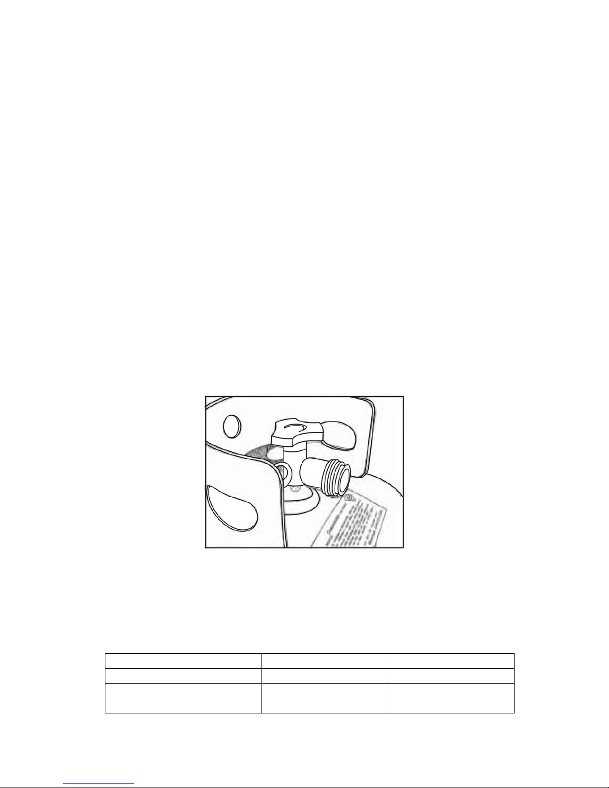
A self contained LP-gas cylinder for use with this appliance must have a
capacity of 20 lbs. and must be equipped with a Type 1 connector and an OPD
(overfill protection device). See Figure 1.
The LP-gas supply cylinder to be used must be constructed and marked in
accordance with the specification for LP-gas cylinders of the U.S. Department
of Transportation (DOT) or the National Standard of Canada, CAN/CSA-B339,
Cylinder, Sphere and Tubes for the Transportation of Dangerous Goods.
The cylinder supply system must be arranged for vapor withdrawal.
The cylinder used must include a collar to protect the cylinder valve.
This appliance shall be used only outdoors in a well-ventilated space and
shall not be used in a building, garage or any other enclosed space.
When this appliance is not is use, the gas must be turned off at the supply
cylinder.
Storage of this appliance indoors is permissible only if the cylinder is
disconnected and removed from the appliance.
Cylinders must be stored outdoors in a well-ventilated area out of the
reach of children .Disconnected cylinders must have threaded valve plugs
tightly installed and must not be stored in a building, garage or any other
enclosed areas.
CSA (Canadian Standards Association) certified to ANSI Z21.97•CSA 2.41-2012
“ Outdoor Decorative Gas Appliances”
Figure 1
SPECIFICATIONS
INPUT 40,000 Btu/hr 30,000 Btu/hr Low fire
Propane Regulator Pressure 11 inches water column
Clearances to combustible
surfaces Sides 24in./61cm Top: 72 in. / 183 cm

5
PARTS IDENTIFICATION LIST
PART DESCRIPTION PART# QTY
A CONTROL KNOB FP0245 1
B GAS VALVE FP0307 1
C THERMOCOUPLE FP0004 1
D LP REGULATOR HOSE FP0308 1
E ELECTRODE FP0003 1
F ORIFICE ELBOW FP0310 1
G IGNITION MODULE FP0006 1
H PROPANE ORIFICE FP0312 1
I “AAA” BATTERY(1.5V) FP0010 1
J HEX BOLT DRIVER HW0008 1
K FOOTCAP FC0560 4
L FOOTCAP FC0624 8
M 1/4" X 15 MM BOLT HW0034 8
N 1/4" X 20 MM BOLT HW0036 4
O 1/4" X 40 MM BOLT HW0086 4
P BOLT COVER HW0105 18
Q WASHERS HW0004 18
R NUTS HW0719 2
S HEX BOLT DRIVER HW0006 1

6
T
FIRE PIT TABLETOP FP0904 1
U
BACK PANEL FP0905 1
V
LEFT SIDE PANEL FP0906 1
W
RIGHT SIDE PANEL FP0907 1
X
DOOR PANEL FP0908 1
Y TILE-1 FP0909 4
Z TILE-2 FP0910 4
AA MIDDLE SUPPORT FP0911 1
BB LP SUPPORT FP0675 1
CC BOTTOM/ TOP
CONNECTOR FP0677/FP0678 1
DD FIRE PAN/BURNER
ASSEMBLY FP0869 1
EE LAVA ROCK SET FP0002 1

7
INSTALLATION
1.Identify parts packed in carton against the parts list. Remove all protective materials and
set parts on a flat, non-abrasive surface.
2. Attach the back panel to side panels by using four 1/4"x40 mm bolts and washers as
shown in Fig.2.Guide bolts through holes in back panel, into pre-drilled holes in the side
panels. Hand tighten only.
Figure 2
3. Attach the middle support to side panels by using four 1/4"x15 mm bolts and washers
as shown in Fig.3.Guide bolts through holes in middle support, into pre-drilled holes in the
side panels. Hand tighten only.
Figure 3
4. Attach the "L" connector to right side panel by using a 1/4"x15 mm bolt and washer as
shown in Fig. 4.Guide bolt through hole in "L" connector, into pre-drilled hole in the right
side panel. Do not over tighten.

8
Figure 4
5. Put the door onto the "L" pre-assembled connector, guide the pin of "L" connector into
the hole under the door Then guide the pin of another "L" connector into the hole upside of
the door, use a 1/4"x15 mm bolt and washer to attach this "L" connector to the right side
panel as shown in Fig.5. Do not over tighten.
Figure 5
6. With the help of another person, carefully place the table top onto the table base. After
making any necessary adjustments to the alignment of the table top and the assembled
base, use four 1/4"x20 mm bolts and washers as shown in Fig.6.Guide the bolts through
the holes under the table top, into the pre-drilled holes in the side panels. Do not tighten
completely.

9
Figure 6
7. Attach the LP support to door panel by using four 1/4"x15 mm bolts and washers as
shown in Fig.7. Do not over tighten.
Figure 7
8. Place gas tank onto the LP support as shown in Fig. 8.
Connect the regulator as shown in figure.8a. Screw the black handle clock-wise to
tighten. Turn the handle counter clock-wise to remove. The hose must point down.
Check that the valve is turned all the way clockwise to the "OFF" position.
Figure 8Figure 8 Figure 8a

10
9. Attach the metal ring ( as shown in Fig .9) pre-fitted with gas hose which is connected to
the table top , into the hole of the door panel, then use hex bolt driver to screw 1/4"x5mm
nut as shown in Fig.9a. The gas tank has fixed as shown in Fig.10
Figure 9 Figure 9a Figure 10
10. After making any necessary adjustments to the parts, use the hex bolt driver to tighten
all bolts.
Note: each bolt must be tightened a few revolutions at a time.
Repeat until all bolts are tight. Do not over tighten. Over tightening may strip bolts. Cover
all bolts with covers.
11. Note the clear bumpers spaced evenly throughout the inside of the table top. Carefully
place tiles inside table top, resting on the clear bumpers as shown in Fig.11.
Figure 11
12. Pour the lava rocks into the burner pan
completely covering the burner. See Fig. 12.
Ignition Well
Figure 12

11
13. Remove the cardboard cover from the ignition well as shown in Fig.13. Remove any
lava rock or fire ice on top of ignition well.
Cardboard Cover
14. Open the tank valve. Apply a solution of soapy water to the tank-regulator connection
and to the valve-hose connection to check for leaks as shown in Fig.14. If soap bubbles
continue to form, the connection has a leak. If a leak is found, close the tank valve and
tighten all connections.
NOTE: NEVER USE A FLAME TO CHECK FOR LEAKS.
BATTERIES
Make sure the control knob is in the "OFF" position.
Unscrew the push button cap on the ignition module
located on the control panel to access the battery
compartment. The ignition module requires one Alkaline
AAA size battery (1.5V). The negative (-) end goes in
first. See Figure 15. Dispose of battery safely. May
explode or leak if charged or disposed of in fire. Make
sure of the polarity. Mercury and cadmium free.
Figure 13
Checking the tank-regulator for leaks
Figure 14
Figure 15

12
LIGHTING INSTRUCTIONS
Warning: If these instructions are not followed exactly, a fire or explosion may result
causing property damage, personal injury or loss of life.
1. Make sure the control knob is in the "OFF" position. See Figure 16 Open the tank valve
alltheway.
2. Push in the igniter button. You will hear a slight clicking sound. With the igniter button
pushed in, push and turn the control knob to the “ON” position. the fire should light within a
few seconds. Once the flame is lit, release the igniter button and continue to hold the
control knob in for 10 to 15 seconds. Release the control knob. The control knob should
pop back out and then remain lit.
Note: If the fire does not light, turn the knob to the “OFF” position and wait five (5) minutes
before trying again.
3. To turn down the flame, push the control knob in slightly and turn to Medium (medium
or Low (small flame).
4. To shut down the fire pit, turn the control knob to the “OFF” position and turn off the tank
valve.
IGNITER BUTTON CONTROL KNOB
Figure 16

13
The flames should look like those in Figure 17. To clean the
burner, use a soft brush after the burner has cooled completely.
Never use a vacuum cleaner on the burner. It is recommended
that the fire pit be stored indoors during the winter if it will be
subjected to freezing temperatures. The LP cylinder must be
disconnected and removed from the appliance before the
appliance can be stored indoors.
Always purchase the correct size and grade of battery most suitable for the intended use.
Replace all batteries of a set at the same time. Clean the battery contacts and also those
of the device prior to battery installation. Ensure batteries are installed correctly with
regard to polarity (+ and -). Remove batteries from equipment which is not to be used for
an extended period of time. Remove used batteries promptly.
TROUBLESHOOTING GUIDE
PROBLEM CAUSE REMEDY
No Propane Gas at Burner
Check that gas tank valve is
open. Turn control knob to “ON”
and push control knob in. Make
sure tank has propane gas.
No Spark at Electrode
Check that AAA battery is
installed with negative (-) end
first and has a charge. Check
that the wire is connected to the
ignition module. Check that the
electrode is not cracked or
broken.
Burner won’t light
Lack of oxygen Remove excess lava rocks or
fire ices from around the ignition
well.
Thermocouple not in flame
Check that the tip of the
thermocouple is even with the
top of the ignition well. Remove
any lava rocks from the igntion
well.
Thermocouple connection
at the main control valve is
loose
Tighten the thermocouple nut at
the back of the valve.
Burner won’t stay
lit after lighting
No Lava Rocks on Burner Cover the burner with lava rocks
per the instructions
Figure 17
MAINTENANCE

14
90-DAYS LIMITED WARRANTY
What is Covered Under This Warranty?
Fire pits are warranted against defects in material or workmanship for 90 days.
How Do I Obtain Warranty Service?
To obtain warranty service, you must contact our customer service center within the
relevant warranty period and provide us with a copy of your dated register receipt as proof
of the purchase date. We reserve the right to request photographs and/or return of the
defective item(s) and/or such other evidence relating to any claim as we shall reasonably
require. Please call our customer service center at 1-800-537-8484 for additional warranty
claim details and procedures.
What are the Limitations and Exclusions of this Warranty?
Warranty Limitations: This warranty is subject to the limitation set forth above. In addition,
this warranty is made to the original purchaser only and is effective only if items are
purchased from one of our authorized dealers. This warranty is not transferable. For
warranty replacements based on warranty claims submitted within ninety (90) days of
purchase, we will not be responsible for charges associated with shipments outside
continental North America at any time or for any reason.
Warranty Exclusions: This warranty is subjected to the exclusions set forth above. In
addition, the following are excluded from coverage under this warranty: any item used for
commercial, contract or any other non-residential purpose; clearance items, display
models or items purchased “as is”; freight damage; items subject tomisuse, abuse, neglect
or lack of proper care or maintenance (including without limitation as provided in any “care
and maintenance guide” or similar information we provide); normal wear and tear; damage
caused by acts of nature, acts of force majeure, vandalism, fire or other causality, or
improper assembly; hardware against corrosion or rusting; purchased or replacement
parts; and all plastic parts. Also excluded are loss of use or time; inconvenience; money;
travel; packaging; or incidental, special or consequential damages of any kind.
Replacement of defective items or parts as provided herein shall constitute your sole and
exclusive remedy for items which are not as warranted. In no event shall our responsibility
exceed the purchase price of the item found to be other than as warranted. This warranty is
the exclusive statement of your rights with respect to items you have purchased and
supersedes any other express warranty or statement, written or oral, made in connection
with the purchase and sale of such items. The term ”item” when used herein in the singular
refers to the specific piece found to be defective, and not to the entire set of which the item
is a part.
Some states do not allow exclusion or limitation of incidental or consequential damage, so
that limitation may not apply to you. This warranty gives you specific legal rights, and you
may also have other rights that vary from state to state.
Table of contents
Other Emilyrose Outdoor Fireplace manuals
Popular Outdoor Fireplace manuals by other brands

Backyard Creations
Backyard Creations ST. CROIX HD WT17YL Safety manual

pleasant hearth
pleasant hearth OFG419T owner's manual

FMI
FMI Outland Firebowl FMPPC2F owner's manual

Endless Summer
Endless Summer GAD15275MG owner's manual

Astria Fireplaces
Astria Fireplaces Odyssey36ZNM Product information

Agio
Agio DRC02200 Assembly instructions