Parameter Definitions
:Input Type and Functions (Default=3)
0 :
1 :
(INC)
Down (DEC)
, Down
.(INC/DEC)
. (INC/INC)
Down (UP/DOWN)
x1 .(for Incremental Encoder)
x2 .(for Incremental Encoder )
x4 .(for Incremental Encoder )
2 :
3 :
4 :
5 :
6 :
7 :
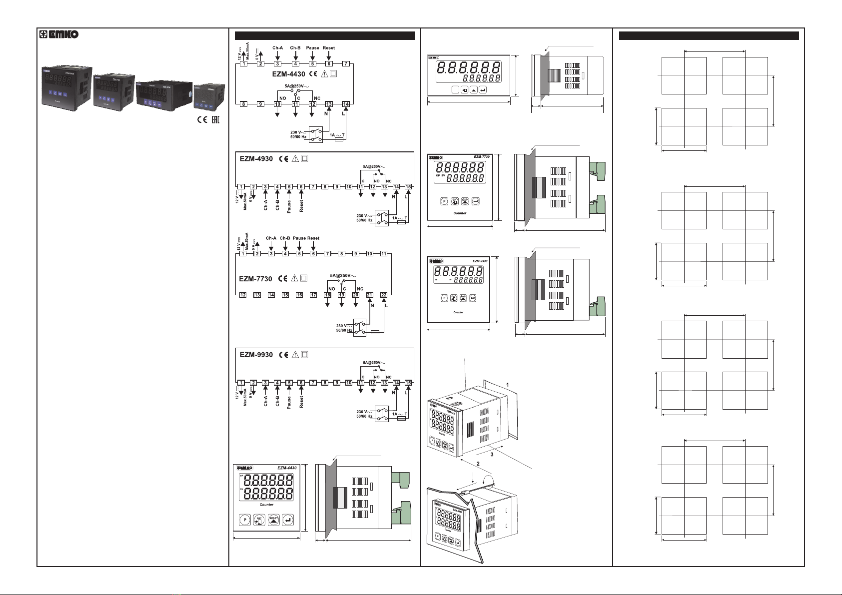
Upcount on rising edge of Ch-Ainput.
count on rising edge of Ch-Ainput.
Upcount on rising edge of Ch-Ainput count on rising
edge of Ch-B input
Upcount on rising edge of Ch-Ainput,Upcount on rising edge of
Ch-B input
Upcount on rising edge of Ch-A input when Ch-B is at 0
count on rising edge of Ch-Awhen Ch-B is at 1.
Phase Shifting
Phase Shifting
Phase Shifting
: (Default=0)Filter time for Ch-A and Ch-B Inputs
It is used to protect against the electrical contact debounce or the
signal that is less than the determined pulse time.
It can be adjusted from to milisecond.
: (Default=50)Filter time for Reset and Pause Inputs
It is used to protect against the electrical contact debounce or the
signal that is less than the determined pulse time.
It can be adjusted from to milisecond.
:Count Direction (Default=0)
Downcount. ( Preset--> 0 )
Upcount. ( 0 -->Preset )
:Sensor Type Selection (Default=0)
PNP Sensor type is selected.
NPN Sensor type is selected.
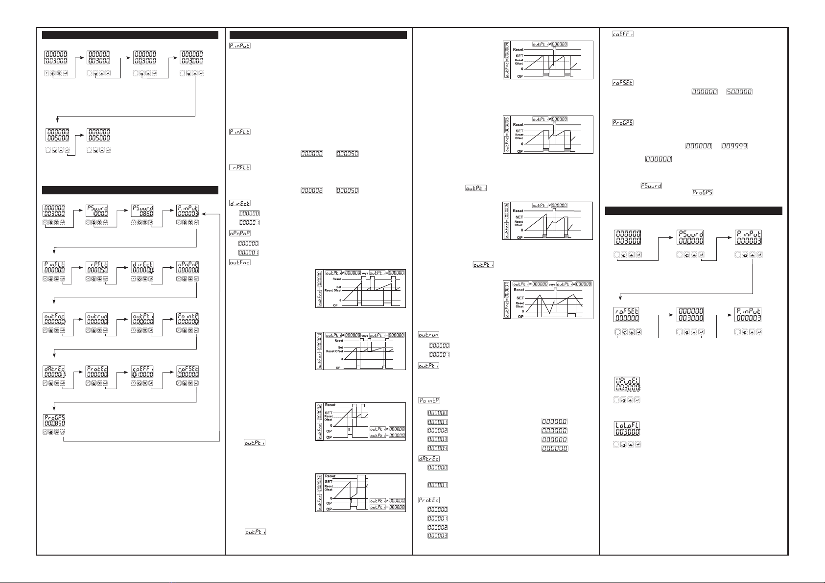
:Output Functions (Default=0)
0:
Manuel Reset-1: Process
counts,until manuel reset
happens.When count
value reaches the Set
value,Output Position is
changed.
Manuel Reset-2: Process
counts,until manuel reset
hap p e ns.W h e n coun t
value reaches the Set
value,Output Position is
changed.Counting doesn’t
change continue over Set
value.Outp ut P os it io n
doesn’t change ,until
manuel reset happens.
2:
Manuel Reset-3: Process
counts,until manuel reset
hap pens . Whe n c ount
value reaches the Set
value,Output Position is
changed.After the end of
the Output Pulse Time
output positions
changes the old position.
3:
Automatic Reset-1:When
count value reaches the
Set value,Output position
is changed.Process value
automatically and counting
will continue from “0”(up
cou nt) o r “ Set ”(do wn
count).After the end of
the Output Pulse Time
output positions
changes the old position.
4:
Automatic Reset-2: When
cou nt va lue r each es th e
Set value,Output position
is changed.Counting doesn’t
continue over the Set value.
P r o c e s s v a l u e i s r e s e t
a u t o m a t i c a l l y , c o u n t i n g
continue from “0” (upcount)
or “Set” (downcount) and
Output position changes the old
position at the end of the
output pulse time.
5:
Automatic Reset-3: When
count valu e r e a c h e s t h e
Se t v alu e,O utpu t pos itio n
i s c h a n g e d . C o u n t v a l u e
beco m e s z e ro.(F o r 0 - > P)
Counting restarts on “0” value,
but Set Value is showen on the
P r o c e s s v a l u e s c r e e n .
Output position becomes the old
and the Real count value
can be seen at the end of
output pulse time.
6:
Automatic Reset-4: When
count value reaches the
Set value,Output position
is changed.Count value is
automatically reset and
counting will continue ( for
0->P) and Output position
c h a n g e s t h e o l d
position at the end of the
output pulse time.
7:
:Output Run Type (Default=0)
Normally Energised.
Normally De-energised.
:Output Pulse Time (Default=0.00)
It determines how long Output will be active.It can be adjusted
from 00.00 to 99.99 seconds. If it is 00.00 second ,then it
operates indefinitely.
: Point Position (Default=0)
Between first and second digits.
No point.
Between second and third digits.
Between third and fourth digits.
Between fourth and fifth digits.
: Data Record (Default=1)
Count value is not saved to memory when power is
disconnected.
Count value is saved to memory when power is
disconnected and restored on power up.
:Reset and Set Protection (Default=0)
No Reset and Set protection.
Only Reset button protection is active.
Only Set button protection is active .
Full Protection.Reset and Set button protection is
active.
: Multiplication Coefficient (Default=01.0000)
The Count value that is read from Process input,is multiplied
with this value.Parameter value can be adjusted from
00.0000 to 99.9999.If this parameter is adjusted to
“01.0000” then this parameter has no effect on Process
input count,so Process value equal to the Process input
count.
: Reset Offset (Default=0)
It can be adjusted from to .When
Process is manually reset ,count process starts from this
value.
: Program Password (Default=0)
It is used for accessing to the program parameters.
It can be adjusted from to .
If it is ; there is no password protection while
entering to the program parameters.
If operator accesses to the program parameters by entering
“0” to ,then the operator can only see the parameter
without changing,except
Failure Messages in EZM-XX30 Programmable Counter
Reset Offset Parameter
1- If Actual Value is flashing and counting is
stopped ;
It appears if any of the count value is bigger
than the maximum count value.
To remove this warning and reset the count
value press button.RESET
2- If Actual Value is flashing and counting is
stopped ;
It appears if any of the count value is lower than
the minimum count value.
To remove this warning and reset the count
value press button.RESET
W h e n
button is pressed,
password entering
screen will appear.
P R O G The most
Significant digit
of the parameter
(4th digit for
this parameter)
Flashes.
Press ENTER
Button without
entering the
password.
No digit
flashes.
By pressing
ENTER
button, user
can see all
parameters
except for
program
password.
Press PROG button to exit
from programming mode.
Continue to
press
b u t t o n f o r
scanning the
parameters.
ENTER
Accessing and Changing the Set Values
Main Operation
Screen
Shift button is
pressed,6th digit
of S e t Val u e
starts to flash.
SET Screen
Press Shift
Button again.
5th digit of the
SET value
starts to flash.
4th digit of
the SET
value starts
to flash.
Increase the
flashing digit
with pressing
the Increment
Button.
Save the SET
v a l u e w i t h
pr e ssi n g th e
ENTER Button.
Main Operation
Screen
Accessing to the Program Parameters
Program Password
Press Enter button to access to
the first program (Input Type
and Function) parameter.
Press Enter Button to
access to following
parameter.
When Button
is pressed,password
must be entered for
accessing the program
parameter.
Prog 4th digit of the password
parameter flashes.Enter the
password with using Shift
and Increment Button.
After entered the
Password, press
Enter Button.
Main Operation
Screen Password Screen Password Screen Input Type and Functions
Process Input
Filter
Reset and Pause
Input Filter Count Direction Sensor Type
Selection
Output
Functions
Output Run
Type Output Pulse
Time
Decimal Point
Position
Data
Record
Reset and Set
Protection
Multiplication
Coefficient Reset Offset
Note-1
Note-1
Note-1
Note-1
Note-1
Note 1- Parameter value can be changed with Incrament button.
When the Enter button is pressed,parameter value will be saved
and following parameter is accessed.
Note 2- Press “P” button is exit without saving the parameter
value.Thus Main Operation Screen is appeared.
Counter Counter Counter
Counter Counter Counter
Note-1
Note-1
Press Shift
Button again.
SET Screen
SET Screen SET Screen
Press Enter Button to
access to following
parameter.
Press Enter Button to
access to following
parameter.
Press Enter Button to
access to following
parameter.
Press Enter Button to
access to following
parameter.
Press Enter Button to
access to following
parameter.
Press Enter Button to
access to following
parameter.
Press Enter Button to
access to following
parameter.
Press Enter Button to
access to following
parameter.
Press Enter Button to
access to following
parameter.
Press Enter Button to
access to following
parameter.
Press Enter Button to
access to following
parameter.
Press Enter Button to
access to following
parameter.
1:
Password Screen
Main Operation
Screen Input Type and Functions
Main Operation
Screen Input Type and Functions
Note-1
Note-1
Note-1
Note-1 Note-1
Note-1
Note-1
Automatic Reset-5:Process
counts,until manuel reset
happens.Output pulse time
does not take into considera
tion.This function can be
prefered on systems that,
upcounts or downcounts at
the same time.
O1
O2
SV
S2
RESET
PSET
O1
O2
SV
S2
RESET
PSET
O1
O2
SV
S2
RESET
PSET
O1
O2
SV
S2
RESET
PSET
O1
O2
SV
S2
RESET
PSET
OV
O2
SV
S2
RESET
PSET
OV
O2
SV
S2
RESET
PSET
Counter
Counter
Counter
O1
O2
SV
S2
RESET
PSET
O1
O2
S1
S2
RESET
PSET
O1
O2
S1
S2
RESET
PSET
O1
O2
S1
S2
RESET
PSET
O1
O2
SV
S2
RESET
PSET
O1
O2
S1
S2
RESET
PSET
RESET
PSET
Counter Counter Counter
Counter Counter