9
Min Default
Max
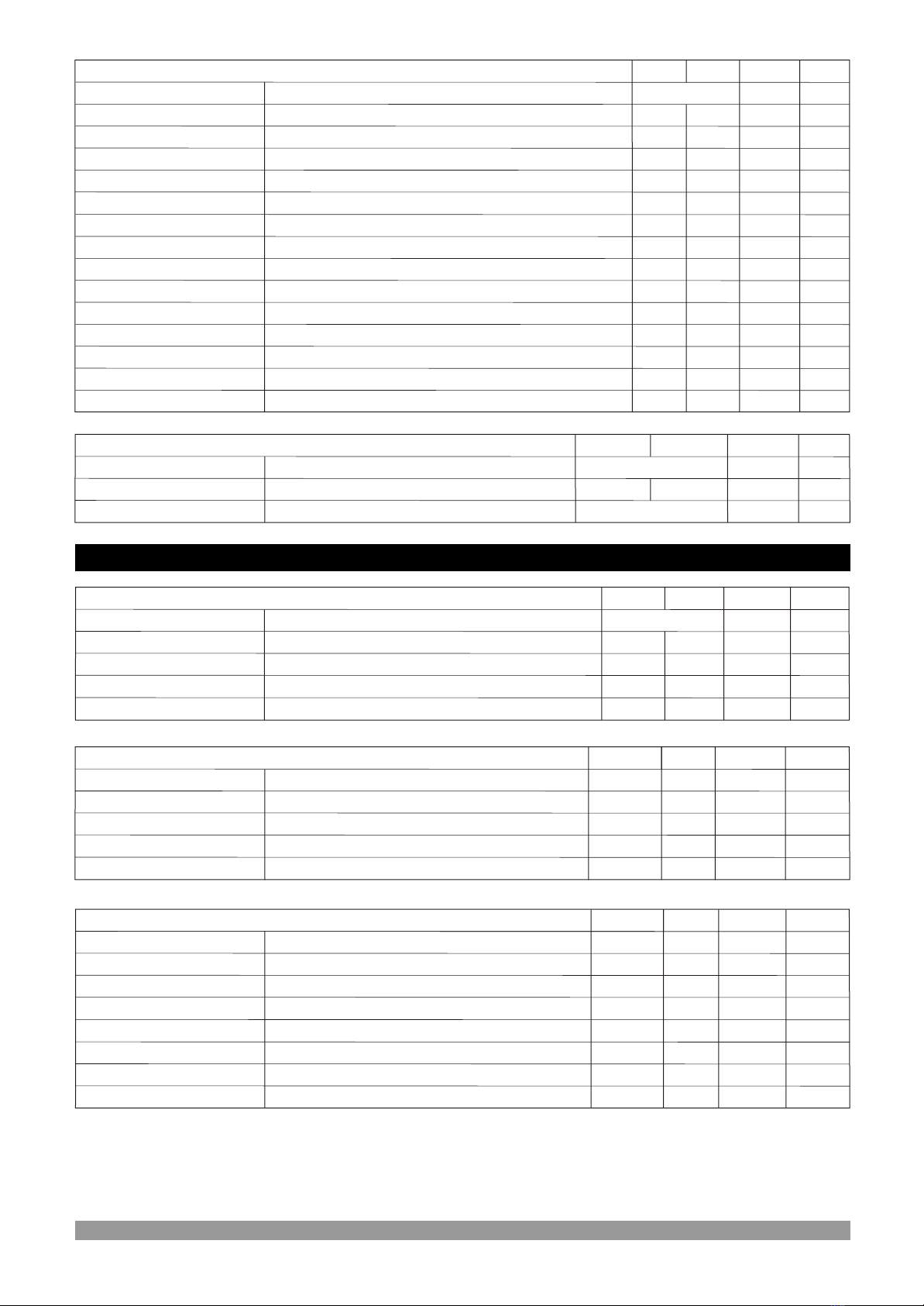
Generator Under Current Pre-Alarm Return
Generator Under Current Actions Delay Time
Generator Over Current Set
Generator Over Current Pre-Alarm
Generator Over Current Pre-Alarm Return
Generator Over Current Actions Delay Time
Generator Short Circuit Current Set
Under cur. reset
Under cur. act.
Under act. delay time
Over cur. set
Over cur. prealarm
Over cur. reset
Over cur. act.
Over act. delay time
Short circuit cur.
Unit
GEN CUR LEVEL & ACT (Generator->Current level & act.)
Generator Under Current Set
Under cur. set
Under cur. prealarm Generator Under Current Pre-Alarm
0
0(dis)
0
0
9999
3
99
9999
9980
dis
2
9999
AV
AV
0
0(dis)
0
0(dis)
0
0
0(dis)
9999
9999
9999
3
99
9999
9999
1
dis
5
dis
2
9999
9990
AV
AV
AV
AV
AV
Sec
Sec
Generator Under Current Actions
0 - Disable
1 - Warning (Alarm Only, No Shutdown)
2 - Electrical Trip (Alarm/Off Load Generator
Followed By Shutdown After Cooling)
3 - Shutdown (Alarm And Shutdown)
Generator Over Current Actions
0 - Disable
1 - Warning (Alarm Only, No Shutdown)
2 - Electrical Trip (Alarm/Off Load Generator
Followed By Shutdown After Cooling)
3 - Shutdown (Alarm And Shutdown)
9999
9999
9999
9999
9999
9999
kVA
kVA
kVA
kVA
0(dis)
0(dis)
0
0(dis)
0(dis)
0
Min Default
Max
Generator Under Power Shutdown
Generator Under Power Pre-Alarm
Generator Under Power Pre-Alarm Return
Generator Over Power Shutdown
Generator Over Power Pre-Alarm
dis
5
Generator Over Power Pre-Alarm Return
kVA
kVA
Under power shutdown
Under power prealarm
Under power reset
Over power shutdown
Over power prealarm
Over power reset
Unit
Shutdown delay time Generator Power Shutdown Delay Time
GEN POWER LEVEL (Generator->Power level)
0 99 2 Sec
dis
dis
0
dis
Note: dis = disable
75.0
30.0(dis)
75.0
75.0
Hz
30.0(dis)
Min Default
Max
Generator Under Frequency Pre-Alarm
Generator Under Frequency Pre-Alarm Return
Generator Over Frequency Shutdown
Generator Over Frequency Pre-Alarm
Generator Over Frequency Pre-Alarm Return
45.0
46.0
58.0
55.0
54.0
Generator Frequency Shutdown Delay Time
Hz
Hz
Hz
Hz
30.0
30.0(dis)
30.0
75.0
75.0
Under freq prealarm
Under freq reset
Over freq shutdown
Over freq prealarm
Over freq reset
Shutdown delay time
Unit
GENERATOR FREQ LEVEL (Generator->Frequency level)
75.0
75.0
Hz
30.0
Nominal Alternator Frequency 50.0
43.0 Hz
Nominal frequency
Under freq shutdown Generator Under Frequency Shutdown 30.0(dis)
0.0 10.0 1.0 Sec
Reverse Power Set
Reverse Power Action Delay Time
-9999
0(dis)
0
0
3
99
0
0(dis)
2
kW
Sec
Reverse Power Actions
0 - Disable
1 - Warning (Alarm Only, No Shutdown)
2 - Electrical Trip (Alarm/Off Load Generator
Followed By Shutdown After Cooling)
3 - Shutdown (Alarm And Shutdown)
Reverse power set
Reverse power act.
Rv.pow.act.delay time