EMKO EPLC9600-CHANNEL8 User manual

EPLC9600-CHANNEL8 96x96 1/4 DIN PT100 SCANNER
EPLC9600- 96 x 96 DIN 1/4CHANNEL8
8 Channel PT-100 Scanner
Introduction Manual. ENG EPLC-9600 CHANNEL8 V04 07/13
- 128 x 64 Graphical LCD display
- 8 PT-100 temperature sensor inputs
- ON-OFF control
- Relay or (pnp “source”) transistor output
- Sensor error detection
- Adjustable temperature offset
- 3 Different alarm and pre-alarm types for each channel
(High, Low and Band Alarms)
- User defined channel labels
- Display scan modes
- Operating with Real Time Clock (RTC)
- ModBus RTU communication protocol
(RS-232, RS-485 and Ethernet communication)
- Data Logging to USB Flash Memory
- Adjustable data logging time interval
- Password protection for programming mode

2
Instruction manual of EPLC9600-CHANNEL8 consists of two main sections. Explanation
of these sections are below. Also, there are other sections which include order information and
technical specifications of the device. All titles and page numbers in instruction manual are in
“CONTENTS” section. User can reach to any title with section number.
Installation:
In this section, physical dimensions of the device, panel mounting, electrical wiring,
physical and electrical installation of the device to the system are explained.
Operation
Also in these sections, there are warnings to prevent serious injury while doing the
physical and electrical mounting or using the device.
Explanation of the symbols which are used in these sections are given below.
and Parameters:
In this section user interface of the device, accessing to the parameters, description of the
parameters are explained.
ABOUT INSTRUCTION MANUAL
a
c
i
This symbol is used to determine the dangerous situations as a result of an electric
shock. User must pay attention to these warnings definitely.
This symbol is used for safety warnings. User must pay attention to these
warnings.
This symbol is used to determine the important notes about functions and usage of
the device.

CONTENTS
3
1.PREFACE............................................................................................................................................
1.1 GENERAL SPECIFICATIONS
1.2 ORDERING INFORMATION
1.3 WARRANTY
1.4 MAINTENANCE
2.INSTALLATION....................................................................................................................................
2.1 GENERAL DESCRIPTION
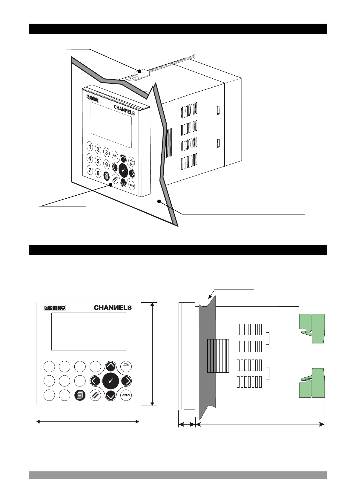
2.2 FRONT VIEW AND DIMENSIONS OF EPLC9600-CHANNEL8
2.3 PANEL CUT-OUT
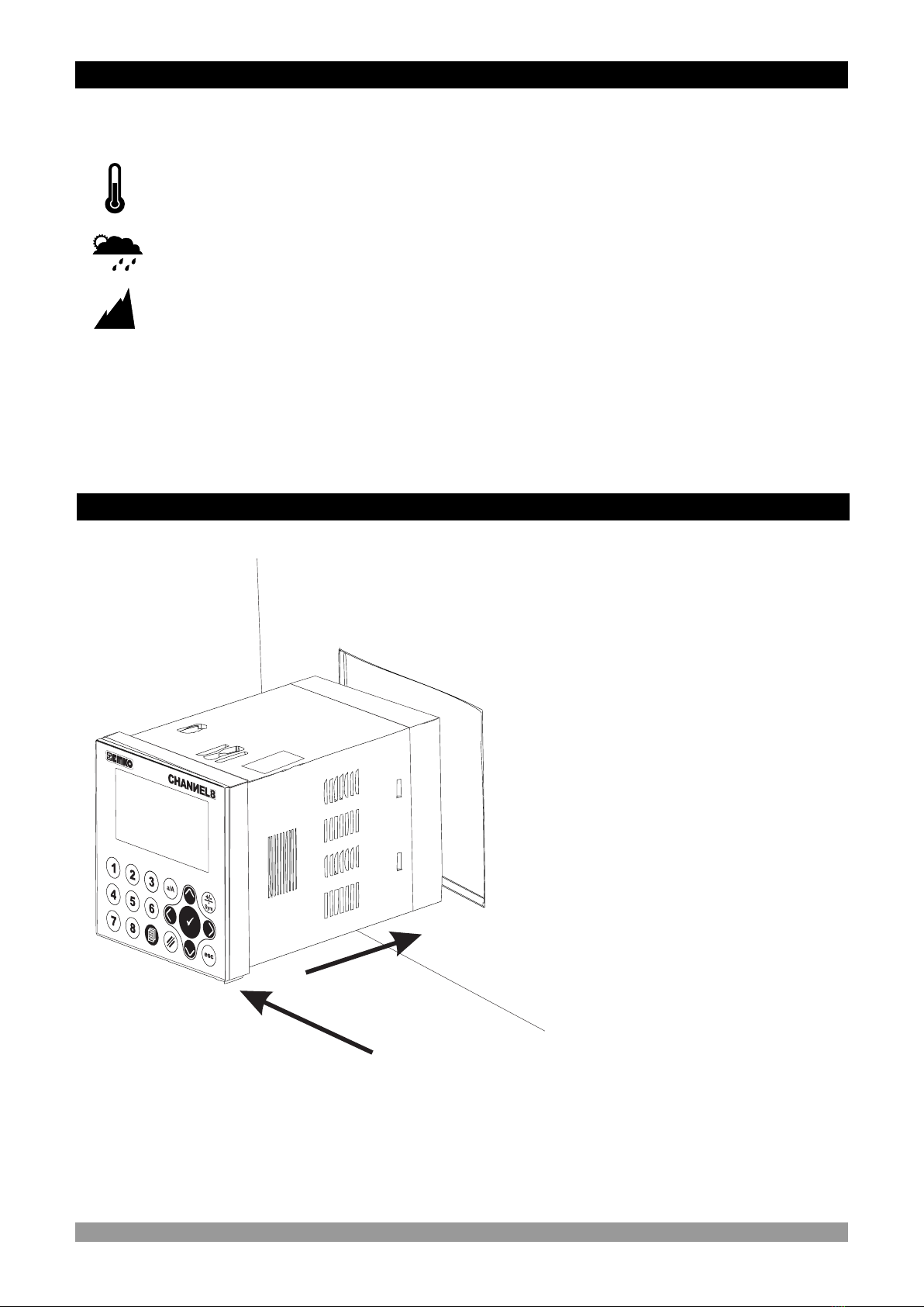
2.4 ENVIRONMENTAL RATINGS
2.5 PANEL MOUNTING
2.6 INSTALLATION FIXING CLAMP
2.7 REMOVING FROM THE PANEL
3.ELECTRICAL WIRING........................................................................................................................
3.1 TERMINAL LAYOUT AND CONNECTION INSTRUCTIONS
3.2 ELECTRICAL WIRING DIAGRAM
3.2.1 DEVICE WITH RELAY OUTPUTS
3.2.2 DEVICE WITH TRANSISTOR OUTPUTS
3.3 SUPPLY VOLTAGE INPUT CONNECTION OF THE DEVICE
3.4 SUPPLY VOLTAGE INPUT CONNECTION OF TRANSISTOR OUTPUTS
3.5. GALVANIC ISOLATION TEST VALUE OF EPLC9600-CHANNEL8 WITH RELAY OUTPUTS
3.6. GALVANIC ISOLATION TEST VALUE OF EPLC9600-CHANNEL8 WITH TRANSISTOR
OUTPUTS
4. CABLE CONNECTION BETWEEN RS232 TERMINAL OF THE DEVICE AND PC ........................
5. CONNECTION FOR RS485 SERIAL COMMUNICATION.................................................................
6. DEFINETION OF THE FRONT PANEL AND ACCESSING TO THE PARAMETERS.......................
6.1 DEFINETION OF FRONT PANEL
6.2 MAIN OPERATION SCREEN DEFINETION
6.3 ACCESSING TO THE OPERATOR PARAMETER PAGES
6.4 ACCESSING TO THE TECHNICIAN PARAMETER PAGES
6.5 OPERATOR PAGES PARAMETERS DEFINETIONS
6.6 TECHNICIAN PAGES PARAMETERS DEFINETIONS
6.6.1 PAGE-1 PARAMETERS
6.6.2 PAGE-2 PARAMETERS
6.6.3 PAGE-3 AND PAGE-4 PARAMETERS
6.6.4 RS232 SETUP PAGES PARAMETERS
6.6.5 RS485 SETUP PAGES PARAMETERS
6.6.6 USB SETUP PAGES PARAMETERS
6.6.7 ETHERNET SETUP PAGES PARAMETERS
6.6.8 REAL TIME (RTC) SETUP PAGES PARAMETERS
7.OPERATION GRAPHICS OF ALARM AND PRE-ALARM TYPE.......................................................
8.MODBUS ADDRESS...........................................................................................................................
8.1 OUTPUT ADDRESSES
8.2 PROCESS VALUES ADDRESSES
9.SPECIFICATIONS................................................................................................................................
10.OTHER INFORMATIONS..................................................................................................................
Page 5
Page 19
Page 12
Page 7
Page 40
Page 39
Page 41
Page 21
Page 20
Page 41

4
Manufacturer’s Name : EMKO ELEKTRONIK A.S.
Manufacturer’s Address : DOSAB, Karanfil Sk., No:6,
16369 Bursa, TURKEY
The manufacturer hereby declares that the product:
Product Name : CHANNEL8 (8 Channel PT-100 Scanner)
Type Number : EPLC9600
Product Category : Electrical equipment for measurement, control and
laboratory use
Conforms to the following directives :
2006 / 95 / EC The Low Voltage Directive
2004 / 108 / EC The Electromagnetic Compatibility Directive
has been designed and manufactured to the following specifications:
EN 61000-6-4:2007 EMC Generic Emission Standard for Industrial Environments
EN 61000-6-2:2005 EMC Generic Immunity Standard for Industrial Environments
EN 61010-1:2001 Safety Requirements for electrical equipment for measurement, control
and laboratory use
When and Where Issued Authorized Signature
nd
22 June 2011 Name : Serpil YAKIN
Bursa-TURKEY Position : Quality Manager
EU DECLARATION OF CONFORMITY

5
EPLC9600
CHANNEL8
PT-100(2-wire)
Alarm Outputs
EPLC9600-CHANNEL8 series 8 channel PT100 scanner devices are designed for
measuring and logging temperature. They can be used in many applications with their PT-100
process input, alarm outputs, selectable alarm functions, RS-232 / RS-485 / Ethernet / USB
communications.
Application Fields
Glass
Plastic
Petro-Chemistry
Textile
Automative
Machine production industries
etc...
Applications
Heating
Baking Ovens
Incubators
Storages
Air Conditioning
etc..
1.Preface
1.1 General Specifications
RS232
Communication
Standard
RS485
Modbus RTU Protocol
Communication
Optional
ETHERNET
Communication
Optional
USB Temperature Data Logging
Communication
Optional
Standard
Relay Outputs
Alarm Outputs
Optional
Transistor Outputs
Temperature Alarm Out
Process Inputs
Modbus RTU Over TCP
Modbus RTU TCP/IP
Protocol
Standard
Universal Supply Input
100-240 V V, 50/60Hz
Optional Supply Input
24V V 50/60Hz, 24V Z
Power Supply
Input

6
1.2 Ordering Information
All order information of EPLC9600-
CHANNEL8 are given on the table at left.
User may form appropriate device
configuration from information and codes
that at the table and convert it to the ordering
codes.
Firstly, supply voltage then other
spesifications must be deteermined. Please
fill the order code blanks according to your
needs.
Please contact us, if your needs are out of
the standards.
1.3 Warranty
EMKO Elektronik warrants that the equipment delivered is free from defects in material and
workmanship. This warranty is provided for a period of two years. The warranty period starts from
the delivery date. This warranty is in force if duty and responsibilities which are determined in
warranty document and instruction manual performs by the customer completely.
1.4 Maintenance
Repairs should only be performed by trained and specialized personnel. Cut power to the device
before accessing internal parts.
Do not clean the case with hydrocarbon-based solvents (Petrol, Trichlorethylene etc.). Use of
these solvents can reduce the mechanical reliability of the device. Use a cloth dampened in ethyl
alcohol or water to clean the external plastic case.
EPLC9600-CHANNEL8
( 96 x 96 1/4 DIN)
2RS-232 (up to 115200 baudrate, “No isolation”)
Standard Serial Communication
C
Outputs
B
R
EDCB
2
10 Relay outputs with 2 common
for each NO contact 5A max. (5A@250V at resistive load)
for each Common contact 15A max (15A@250V at resistive load)
T10 pnp “source” Transistor outputs
Output current 1A Max. for each transistor output.
0None
Optional Communication-1
D
4RS-485 (up to 115200 baudrate, “500VAC isolation”)
EETHERNET (10Mbit/s, “1500VAC isolation”)
0None
Optional Communication-2
E
UUSB (USB2.0 “for temperature data logging”)
.
A
.
1
Supply Voltage
A
2
9Customer
100...240V V (- %15;+%10) 50/60Hz
24VV(-%15;+%10) 50/60Hz 24VZ(-%15;+%10)

7
In package ,
- One piece unit
- Two pieces mounting clamps
- One piece instruction manual
A visual inspection of this product for possible damage occured during shipment is
recommended before installation. It is your responsibility to ensure that qualified
mechanical and electrical technicians install this product.
If there is danger of serious accident resulting from a failure or defect in this unit, power
off the system and separate the electrical connection of the device from the system.
The unit is normally supplied without a power supply switch or a fuse. Use power switch
and fuse as required.
Be sure to use the rated power supply voltage to protect the unit against damage and to
prevent failure.
Keep the power off until all of the wiring is completed so that electric shock and trouble
with the unit can be prevented.
Never attempt to disassemble, modify or repair this unit. Tampering with the unit may
results in malfunction, electric shock or fire.
Do not use the unit in combustible or explosive gaseous atmospheres.
During the equipment is putted in hole on the metal panel while mechanical installation
some metal burrs can cause injury on hands, you must be careful.
Montage of the product on a system must be done with it’s fixing clamps. Do not do the
montage of the device with inappropriate fixing clamp. Be sure that device will not fall
while doing the montage.
It is your responsibility if this equipment is used in a manner not specified in this
instruction manual.
Before beginning installation of this product, please read the instruction
manual and warnings below carefully.
2.Installation
c

8
Front Panel
IP65 protection
NEMA 4X
Panel surface
(maximum thickness 15 mm / 0.59 inch)
Mounting Clamp
2.1 General Description
2.2 EPLC9600-CHANNEL8 Front View and Dimensions of
96 mm / 3.78 inch
96 mm / 3.78 inch
12 ± 1 mm / 0.47 inch 84 mm / 3.31 inch
Maximum 15 mm / 0.59 inch
1 2 3
456
7 8
a/A
ü
Sym
+/-
.

2.3 Panel Cut-out
9
129 mm / 5.08 inch (min)
92mm / 3.62 inch
92mm / 3.62 inch
129 mm / 5.08 inch (min)

10
1
2
3
c
2.5 Panel Mounting
During installation into a metal panel, care should be taken to avoid injury from
metal burrs which might be present. The equipment can loosen from vibration
and become dislodged if installation parts are not properly tightened. These
precautions for the safety of the person who does the panel mounting.
2.4 Environmental Ratings
Operating Temperature : 0 to 50 °C
Max. Operating Humidity : 90% Rh (non-condensing)
Altitude : Up to 2000m.
Operating Conditions
Forbidden Conditions:
Corrosive atmosphere
Explosive atmosphere
Home applications (The unit is only for industrial applications)
c
1-Before mounting the device in your
panel, make sure that the cut-out is of
the right size.
2-Check front panel gasket position
3-Insert the device through the cut-out.
If the mounting clamps are on the unit,
put out them before inserting the unit to
the panel.

11
2.7 Removing from the Panel
c
c
Before starting to remove the unit from panel, power off the unit and the
related system.
Montage of the unit to a system must be done with it’s own fixing clamps. Do
not do the montage of the device with inappropriate fixing clamps. Be sure
that device will not fall while doing the montage.
2.6 Installation Fixing Clamp
The unit is designed for panel
mounting.
1-Insert the unit in the panel cut-out
from the front side.
2- Insert the mounting clamps to the
holes that located top and bottom
sides of device and screw up the
fixing screws until the unit
completely immobile within the
panel
1-Loosen the screws.
2-Pull mounting clamps from top
and bottom fixing sockets.
3-Pull the unit through the front
side of the panel
1
2
3
1
2

12
You must ensure that the device is correctly configured for your application.
Incorrect configuration could result in damage to the process being
controlled, and/or personal injury. It is your responsibility, as the installer, to
ensure that the configuration is correct.
Device parameters has factory default values. These parameters must be
set according to the system’s needs.
Only qualified personnel and technicians should work on this equipment.
This equipment contains internal circuits with voltage dangerous to human
life. There is severe danger for human life in the case of unauthorized
intervention.
Be sure to use the rated power supply voltage to protect the unit against
damage and to prevent failure.
Keep the power off until all of the wiring is completed so that electric shock
and trouble with the unit can be prevented.
3.Electrical Wirings
3.1 Terminal Layout and Connection Instructions
c
c
c
c
1 2 3 4 5 6 7 8 9 10 11 12 13 14 15
16 17 18 19 20 21 22 23 24 25 26 27 28 29 30
RS 232
COMMUNICATION
a
a
16 17 18 19 20 21 22 23 24 25 26 27 28 29 30
1 2 3 4 5 6 7 8 9 10 11 12 13 14 15
Screw driver
0,8 x3mm
Torque
0,5Nm
Max. 2.5mm / 0.098 inch
Wire Size:
18AWG/1mm²
Solid /Stranded
1 2 3 4 5 6 7 8 9 10 11 12 13 14 15
16 17 18 19 20 21 22 23 24 25 26 27 28 29 30
RS 232
COMMUNICATION
a
a
16 17 18 19 20 21 22 23 24 25 26 27 28 29 30
1 2 3 4 5 6 7 8 9 10 11 12 13 14 15
USB 2.0 USB 2.0
D +
D -
Terminal layout for
ethernet communication
Terminal layout for
RS485 communication
ETHERNET
COMMUNICATION
RS 485
COMMUNICATION

13
3.2 Electrical Wiring Diagram
Electrical wiring of the device must be the same as ‘Electrical Wiring
Diagram’ below to prevent damage to the process being controlled and
personnel injury.
c
3.2.1 Device with Relay Outputs
RS485, Ethernet and USB communications are optional
i
Relay Outputs
RS 232
COMMUNICATION
5 x 5A@250V V
COMMON-1
COMMON-2
16 21 22 23 24 25 26 27 28 29 30
17 18 19 20
1 2 345678 9 10 11 12 13 14 15
CH-1 ALARM
OUTPUT
CH-2 ALARM
OUTPUT
CH-3 ALARM
OUTPUT
CH-4 ALARM
OUTPUT
CH-5 ALARM
OUTPUT
CH-6 ALARM
OUTPUT
CH-7 ALARM
OUTPUT
CH-8 ALARM
OUTPUT
GENERAL ALR.
OUTPUT
GENERAL PRE- ALR.
OUTPUT
5 x 5A@250V V
USB 2.0
COMMUNICATION
ETHERNET
OR
RS485
COMMUNICATION
PT-100
CH-1
PT-100
PT-100
PT-100
PT-100
PT-100
PT-100
PT-100
CH-2CH-3CH-4CH-5CH-6CH-7CH-8
AGND
(Alarm Outputs for
Channels 1 to 5)
Relay Outputs
(Alarm Outputs for
Channels 6 to 8,
General Alarm Output and
General Pre-Alarm Output )
Common1 Common2
Process Inputs
(PT-100)
CH = CHANNEL
Power Supply Input
(It must be determined in order.)
100...240V V (- %15;+%10) 50/60Hz 7VA
24VV(-%15;+%10) 50/60Hz 7VA
24VZ(-%15;+%10) 7W
L
(+)
N
(-)

14
Electrical wiring of the device must be the same as ‘Electrical Wiring
Diagram’ below to prevent damage to the process being controlled and
personnel injury.
c
3.2.2 Device with Transistor Outputs
RS485, Ethernet and USB communications are optional
i
RS 232
COMMUNICATION
16 21 22 23 24 25 26 27 28 29 30
17 18 19 20
1 2 345678 9 10 11 12 13 14 15
CH-1 ALARM
OUTPUT
CH-2 ALARM
OUTPUT
CH-3 ALARM
OUTPUT
CH-4 ALARM
OUTPUT
CH-5 ALARM
OUTPUT
CH-6 ALARM
OUTPUT
CH-7 ALARM
OUTPUT
CH-8 ALARM
OUTPUT
GENERAL ALR.
OUTPUT
GENERAL PRE- ALR.
OUTPUT
USB 2.0
COMMUNICATION
ETHERNET
OR
RS485
COMMUNICATION
Transistor Outputs
(Alarm Outputs for
Channels 1 to 8,
General Alarm Output and
General Pre-Alarm Output )
10 x 1A@24VZ
POWER
SUPPLY
24VZ ±%15
PT-100
CH-1
PT-100
PT-100
PT-100
PT-100
PT-100
PT-100
PT-100
CH-2CH-3CH-4CH-5CH-6CH-7CH-8
AGND
Process Inputs
(PT-100)
CH = CHANNEL
Power Supply Input
(It must be determined in order.)
100...240V V (- %15;+%10) 50/60Hz 7VA
24VV(-%15;+%10) 50/60Hz 7VA
24VZ(-%15;+%10) 7W
L
(+)
N
(-)

3.3 Supply Voltage Input Connection of the Device
15
c
a
Power Supply
Note-3
14 15
100-240V V (- %15;+%10) 50/60Hz 7VA or,
24VV(-%15;+%10) 50/60Hz 7VA or,
24VZ(-%15;+%10) 7W
L
N
Y
Note-2
Note-1
Note-2: “L” is (+), “N” is (-) for 24V Z Supply Voltage
Make sure that the power supply voltage is same indicated on the instrument.
Switch on the power supply only after that all the electrical connection have
been completed.
Supply voltage range must be determined in order. While installing the unit,
supply voltage range must be controlled and appropriate supply voltage must
be applied to the unit. Controlling prevents damages in unit and system and
possible accidents as a result of incorrect supply voltage.
There is no power supply switch or fuse on the device. So a power supply
switch and a fuse must be added to the supply voltage input. Power supply
switch and fuse must be put to a place where user can reach easily.
Power supply switch must be two poled for seperating phase and neutral.
On/Off condition of power supply switch is very important in electrical
connection. On/Off condition of power supply switch must be signed for
preventing the wrong connection.
External fuse must be on phase connection in Vsupply input.
External fuse must be on (+) line connection in Zsupply input.
c
c
Note-3: External Fuse is recommended
Note-1 :There is an internal 33R W fusible flameproof resistor in
There is an internal 4R7 W fusible flameproof resistor in
100-240 V V 50/60Hz
24VW 50/60Hz
cThe instrument is protected with an internal fuse (Please refer to Note-1 for
information). In case of failure it is suggested to return the instrument to the
manufacturer for repair.
External Fuse
(1 A T)
Power
Supply
Switch

24V Z ( 15%)±
c
a
Supply Voltage
Power
Supply
Switch
Note-1
3.4 Supply Voltage Input Connection of the Transistor Outputs
29 30
c
c
Note-1 : External fuse is recommended.
Make sure that the power supply voltage is the same indicated on the
instrument.
Switch on the power supply only after that all the electrical connections have
been completed.
While installing the unit, supply voltage range must be controlled and
appropriate supply voltage must be applied to the unit. Controlling prevents
damages in unit and system and possible accidents as a result of incorrect
supply voltage.
There is no power supply switch on the device. So a power supply switch must
be added to the supply voltage input. In accordance with the safety regulations,
the power supply switch shall bring the identification of the relevant
instrument.Power supply switch shall be easily accessible by the user.
Power switch must be two poled for seperating phase and neutral. On/Off
condition of power switch is very important in electrical connection. On/Off
condition of power switch must be signed for preventing the wrong connection.
If an external fuse is used, it must be on (+) line connection in Zsupply input.
(-) (+)
Note-2 : Fuse value must be select according to the system.
Note-2
16
This power supply connection is need only when transistor type outputs are
used.
i

2000V V
Relay Outputs
RS 232
RS 485
Usb
2000V V
Ethernet
3.5 Galvanic Isolation Test Values of EPLC9600-CHANNEL8 with Relay Outputs
Analog inputs
17
Supply Input
of Device
14
15
2000V V
2000V V
2000V V
2000V V

Supply Input
of Device
2000V V
Transistor Outputs
RS 232
RS 485
Usb
2000V V1500V V
Ethernet
3.6 Galvanic Isolation Test Values of EPLC9600-CHANNEL8 with Transistor Outputs
Analog inputs
500V V
500V V
Supply Input
of Output Card
2000V V
500V V
500V V
14
15
29
30
18
2000V V
2000V V
2000V V
2000V V

TX
RX
GND
1
2
3
4
56
7
8
9
PC (Personal Computer)
9 Pin DCON connection
Cable Lenght must be
max. 12 meters for
9600 baud rate
1 2 345678 9 10 11 12 13 14 15
16 17 18 19 20 21 22 23 24 25 26 27 28 29 30
TX
NA
RX
GND
NA
NA
19
4. Cable Connection Between RS-232 Terminal of the Device and PC

D+
Rt
MASTER
SLAVE-1
SLAVE-2
SLAVE-N
Rt
D-
RS-232 Ş RS-485
Convertor
PC(Personal Computer)
RS-232
Connection
Cable
32 terminal can be connected in RS-485 line
Rt resistor = 120 W
For communication connection Twisted Pair
cable must be used
Cable lenght can be maximum 1000 meters
in 9600 baud rate.
When baud rate increases, cable lenght must
be decreased.
1 2 345678 9 10 11 12 13 14 15
16 17 18 19 20 21 22 23 24 25 26 27 28 29 30
D -
D +
D-
D+
1 2 345678 9 10 11 12 13 14 15
16 17 18 19 20 21 22 23 24 25 26 27 28 29 30
D +
D -
D-
D+
1 2 345678 9 10 11 12 13 14 15
16 17 18 19 20 21 22 23 24 25 26 27 28 29 30
D +
D -
D-
D+
5. Connection for RS-485 Serial Communication
20
Table of contents