Electric Range (Digital Control E-D)10
>This appliance is a sealed electric radiator designed for
fixed wall-mounted installation.
>This appliance conforms to the standards EN
and EN .
>The appliance is insulation class I and has electrical
protection level IP.
>This appliance complies with European Directive
//EU (CE Marking on all appliances).
>The product is supplied complete with a connection cable
and wall brackets.
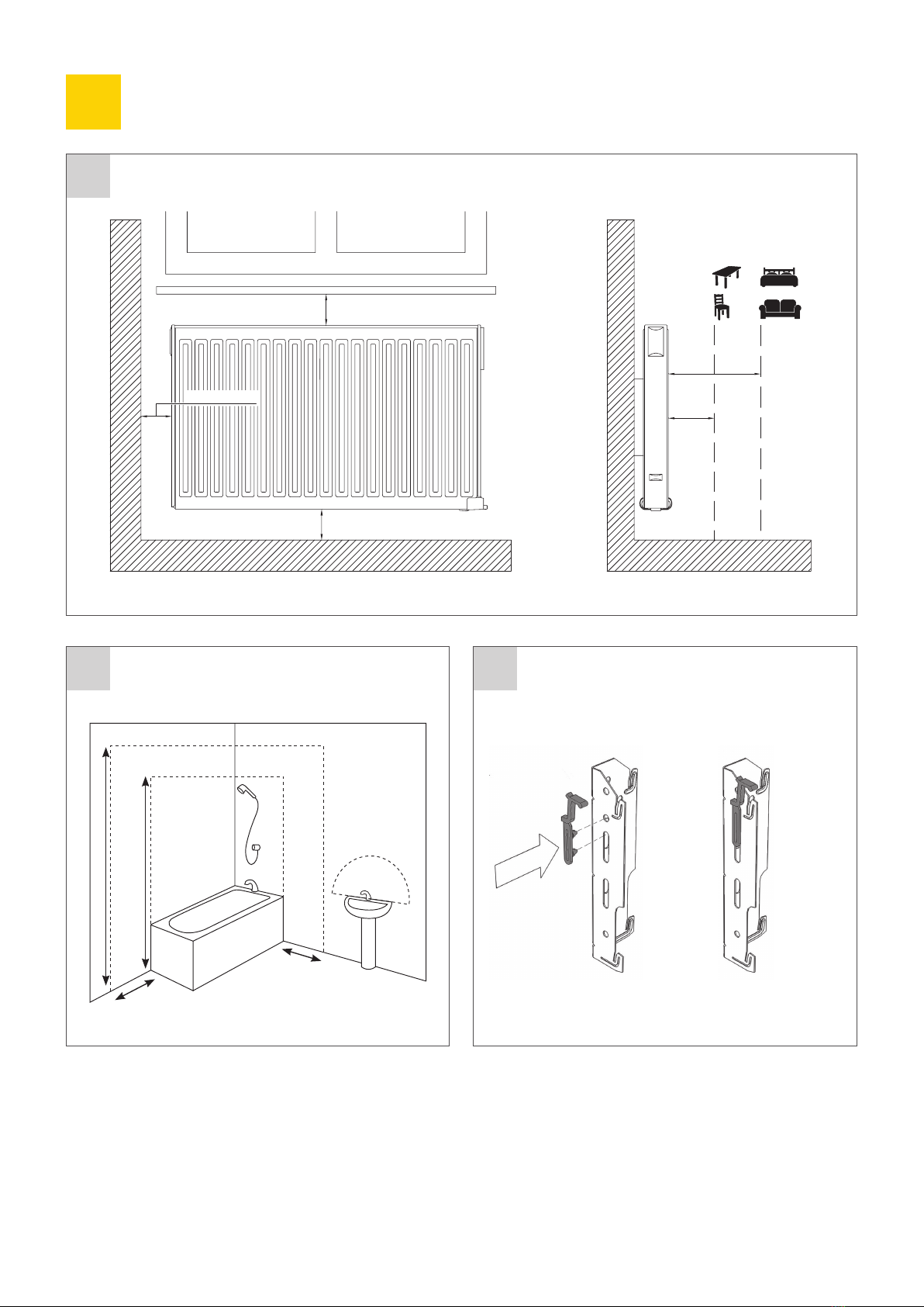
Positioning
>The radiator must be positioned horizontally in order for it
to function correctly.
>The radiator must be positioned according to the applicable
standards.The minimum distances as specified in picture
should be carefully observed.
>The radiator may be positioned inside zone (picture ),
insofar as no operating controls (button, switches, etc …)
are in reach of persons in the bath or under the shower.
>The radiator must be fixed to the wall using the wall
brackets supplied.
>The radiator must not be located underneath an
electrical socket.
Fixing
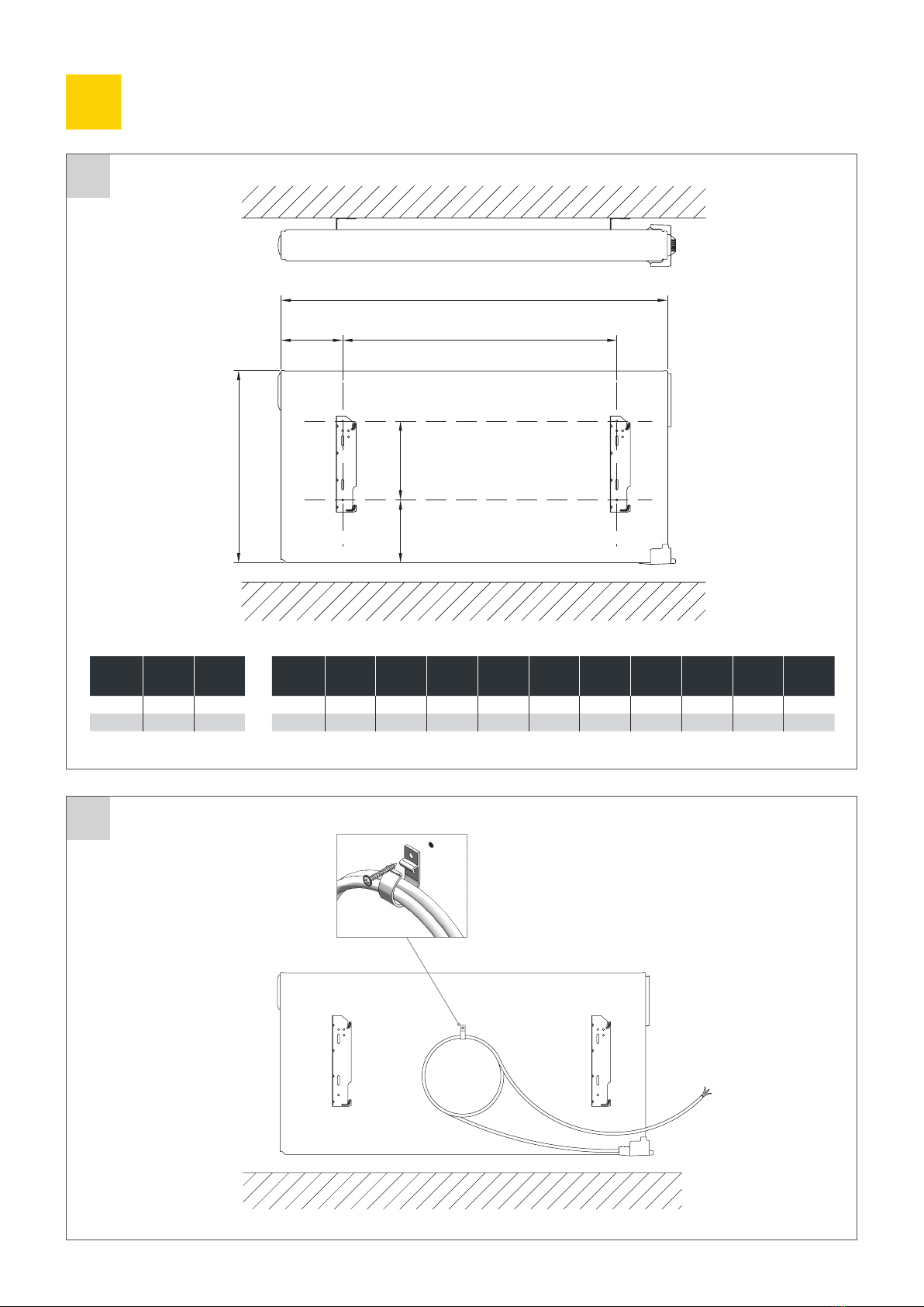
>Mark out the distance between the brackets and the positions
of the screw holes as shown in the table in picture B.
>Ensure that the safety clips are used, as shown in picture A.
NOTE: mm long products are supplied with extra brackets
as a rd bracket must be fitted in the middle of the product.
>For the correct installation of radiators it is essential that
the fixing of the radiator is carried out in such a way that it is
suitable for intended use AND predictable misuse. A number
of elements need to be taken into consideration including the
fixing method used to secure the radiator to the wall, the type
and condition of the wall itself, and any additional potential
forces or weights, prior to finalising installation.
>The fixing materials provided are only intended for
installation on walls made of solid wood, bricks, concrete or
on timber-frame stud walls where the fixing is directly into
the timber. All walls being considered should have no more
than a maximum of mm wall finishing. For walls made of
other materials, for example hollow bricks; please consult
your installer and/or specialist supplier.
In all cases it is strongly recommended that a suitably
qualified professional installer or similar tradesperson
carries out the installation.
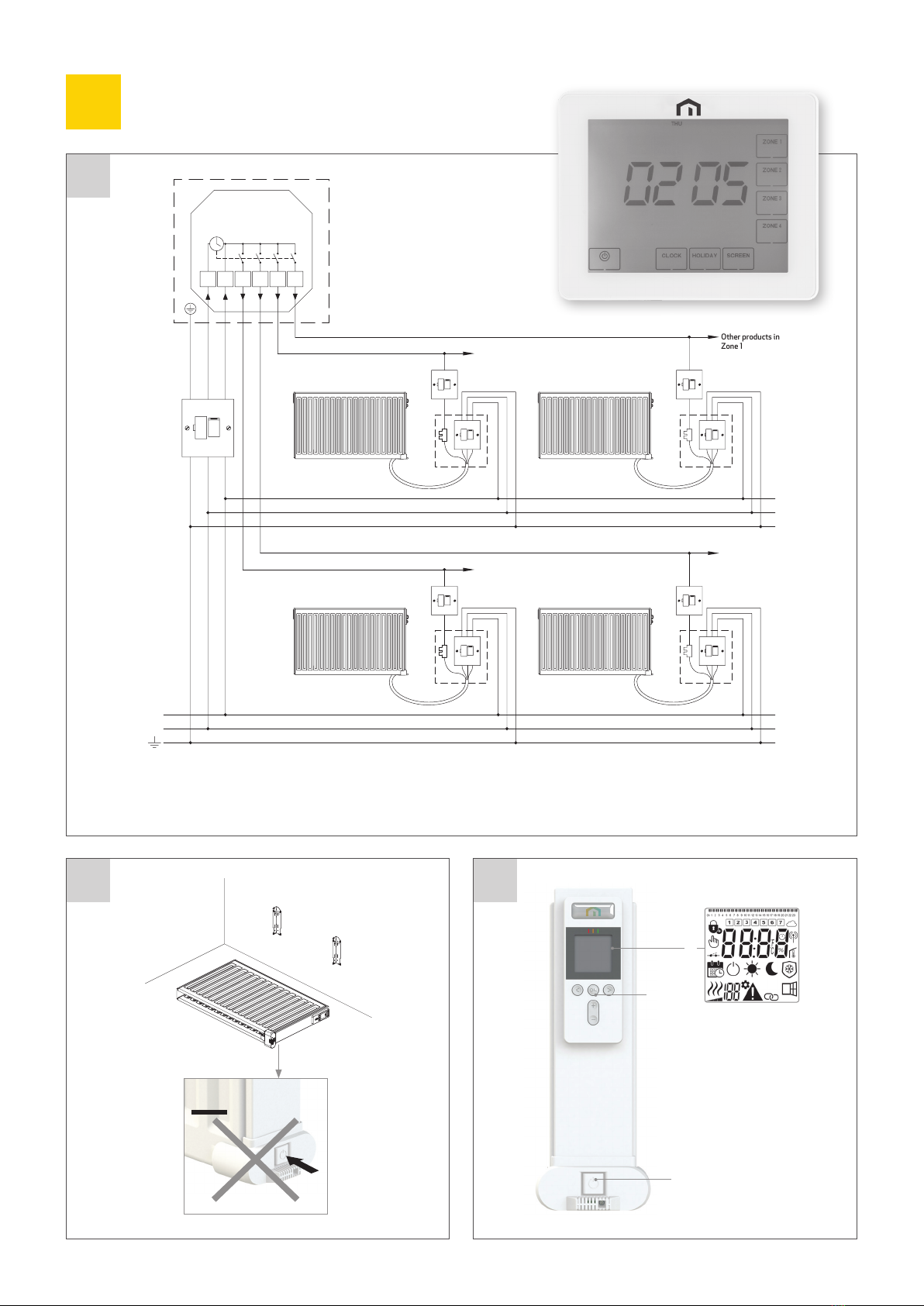
Connection
>The electrical installation must comply with local or
national regulations.
>The radiator should be connected by a suitable and
qualified electrician. Please refer to the wiring diagrams in
pictures A, or B and C for the connection of the radiator.
>The radiator must be connected to the electrical supply,
using a switched fused spur with mm separation on all poles.
>The radiator must be connected to the electrical supply
using the supply cable fitted to the unit.
>If the radiator is installed in a bathroom or shower room, it
must be protected with a residual current device (RCD) with
a rated residual current not exceeding mA.
>The radiator is equipped with a non-resettable overheat
protection that trips off if the radiator overheats. If the
radiator is removed from the wall brackets, even for a short
time, it must without exception be switched off, see picture
D.This may even trip the non-resettable overheat protection.
If the overheat protection trips, its thermal fuse must be
replaced; contact your supplier.
>The On/Off button is located at the bottom of the control side
of the radiator (C, picture ). The radiator should only be
switched “on” when it is correctly installed and secured to the
wall brackets (picture C). When the radiator is switched “on”,
the LCD screen will illuminate and all segments will be displayed
for a few seconds, then disappear, before displaying the
software version. The “Comfort” or previously selected
operating mode screen will appear. The backlight will switch
off after a further seconds.
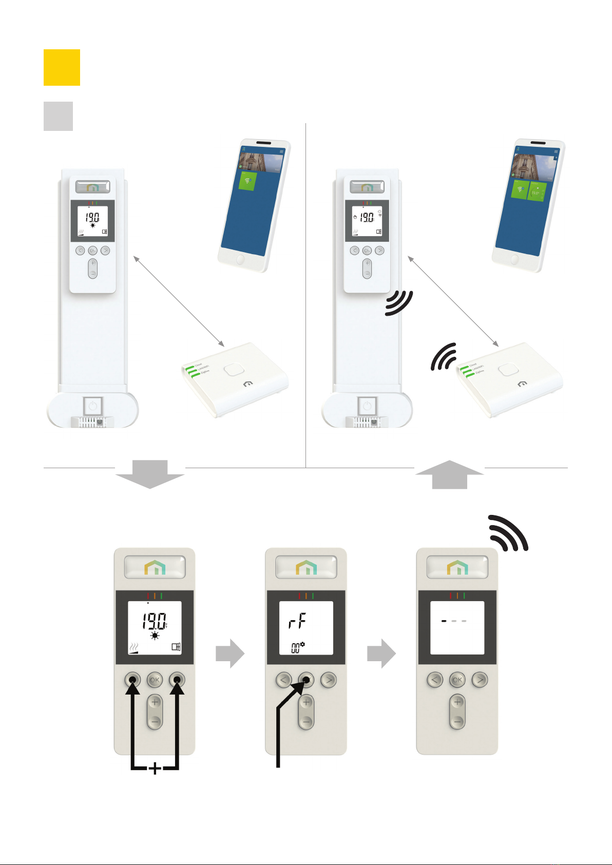
>Display (A, picture )
. Programme information bar or “behaviour” indicator.
. Day of week indicator.
. Cloud icon (with Unisenza PLUS Gateway).
. “RF connection” indicator (with Unisenza PLUS Gateway).
. Adaptive Start indicator.
Installation
.
Operation
.
General Information
.