Emotron EL-FI M20 User manual

WIRING
This wiring example shows how the M20 can be used to control the
starting and stopping circuit of the motor. Other wiring configura-
tions are possible.
1. The current transformer CTMxxx must be placed in the same
phase that is connected to terminal 9, phase L1.
2. For single-phase connection see fig 2.
Fig 1. Connection example
Note!
If the START/STOP is connected according to fig. 1, it is recommended that
terminals 6 and 7 be by-passed during programming. After the programming
is completed the by-pass must be taken out.
3
L1
L2
L3
12
S1 S2
M
3
CTMxxx
MONITOR
N
L1
L2
L3
Max.240V AC
N
K1
STOP
START
8
7
6
C
R1
DIG 5
R2
K1
PRE-
ALARM
34
A-A+
NOTE!
Inpower
down,bothrelays
arealwaysN.O.
-Reset
-Block
-Autoset
INSIDE THE BOX …
This instruction manual describes the installation and commissioning
of the M20 load monitor. The M20 supervises induction motor driven
equipment and provides alarms when abnormal conditions are
detected. The M20’s ability to provide reliable monitoring & protec-
tion ensures production equipment is optimised and expensive break-
downs and interruptions are minimized. Due to the special method of
subtracting motor power losses, the monitor is able to accurately mea-
sure the shaft power supplied by the motor to the application. This
advanced technique allows the M20 to monitor the “application” load
only as opposed to the “total” motor load, which includes the varying
motor losses.
• Check the delivery. Your shipment should contain the M20 load
monitor, a current transformer and this instruction manual.
• Check carefully that the ordered equipment complies with the
motors input voltage and that the current transformer rating is as
stated on the delivery packaging.
• Check that the contents have not been damaged in shipping.
Note!
If in doubt contact your supplier before starting to install or commissioning
the product.
1SAFETY
• Study this manual thoroughly before installing and using the
monitor.
• The monitor must be installed by qualified personal.
• Always disconnect supply circuits prior to installing.
• The installation must comply with standard and local regulations.
• Pay special attention to this SAFETY section and the part marked
“CAUTION!” in the OPERATION section.
• Should questions or uncertainties arise, please contact your local
sales outlet or see section 11 SERVICE.
Note!
Do not remove or break the seal on the housing. The warranty will be can-
celled.
2
Fig 4. Example CTM 025 with 2 windings for an 12 A motor.
Fig 5. Example 1 and 3 windings.
Note!
Normally the appropriate Current Transformer (CT) will have been ordered
and shipped with the M20, check that this is the case; contact the supplier
if in doubt.
Note!
The transformer connection and orientation are not polarity sensitive.
L1
L2
L3
12
S1 S2
M
3
MONITOR
2windings
CTM025
P2
SELECTION CURRENT TRANSFORMER
FOR MOTORS LESS THAN 100A
1. Check the rated motor current on the motor plate.
2. Compare this value with the current in table 1.
3. From table 1, select the current transformer and the appropriate
numbers of windings.
EXAMPLE:
• Rated motor current = 12A.
• Select 10.1-12.5A from the first colon in table 1.
• This gives:
- CTM025 with 2 windings.
Table 1. CT less than 100A.
Note!
Max length of the CTM cable is 1 m (39.37 in).
RATED MOTOR
CURRENT [A]
CURRENT TRANSFORMER TYPE
NUMBER OF WINDINGS
CTM 010 CTM 025 CTM 050 CTM 100
0.4 — 1.0 10
1.01 — 2.0 5
2.01 — 3.0 3
3.1 — 5.0 2
5.1 — 10.0 1
10.1 — 12.5 2
12.6 —25.0 1
26.0 — 50.0 1
51.0 — 100.0 1
4
Continue
ALTERNATIVE EXAMPLE FOR SINGLE-PHASE
CONNECTION
This wiring example shows the deviant power connection to be made
with regard to a single-phase connection. Refer to fig. 1 for the
remaining wiring.
Fig 2. Single-phase connection example.
EXAMPLE - DIGITAL INPUT
The Digital Input use the terminals 5 (DIG) and 6 (C-reference). It can
have either a VAC or a VDC signal. See also section 7 ADVANCED
FEATURES.
Fig 3. Wiring example for digital input.
3
L1
12
M
CTMxxx
MONITOR
N
L1
L2
L3
DIG
K1
8
7
6
C
R1
R2
S1 S2 5
DIG
C
MONITOR +
-
()~
()~
6
5
EL-FI®M20
SHAFT POWER MONITOR
INSTRUCTION MANUAL
Motor shaft output power measurement
Emotron AB
Mörsaregatan 12
Box 222 25
SE-250 24 Helsingborg
Sweden
Tel.: +46 42 169900
Fax: +46 42 169949
www.emotron.com
Protected by utility patent SE 9703952-3
International utility patent application pending WO 9925049
01-2551-01 r1a

Set RATED MOTOR POWER and CURRENT
(Windows 41, 42)
The RATED MOTOR POWER and the RATED MOTOR CURRENT
must be set in window 41 and 42.
Example motor plate:
Programming
1. Go to window 41 (default = 2.2kW).
2. Press or to set the RATED MOTOR POWER as indicated
on the motor plate (see example).
3. Press to confirm the change.
4. Go to window 42 (default = 5.6A).
5. Press or to set the RATED MOTOR CURRENT as indi-
cated on the motor plate (see example).
6. Press to confirm the change.
TYPE: T56BN/4 NR: 948287 Prot. IP: 54
Ser v: S1 Cos ϕ: 0.78 Is. Cl:F
V:Y/∆Hz HP kW RPM A:Y/∆
240/415 50 3 2.2 1400 5.6/9.4
260/440 60 3 2.2 1680 5.8/9.1
ASYNCHROUNOUS THREE-PHASE MOTORS
6:2
ENTER
ENTER
Set NUMBER OF PHASES (Window 43)
The NUMBER OF PHASES must be set according to number of motor
phases. Default is 3 phase.
Programming
1. Go to window 43 (default = 3PH).
2. Press or to set the NUMBER OF PHASES to 1 if a single-
phase motor is used.
3. Press to confirm the change.
6:3
43 3PH
ENTER
43 1PH
Continue
• The Actual Load window will appear automatically if no keys are
pressed for longer than 1 minute.
• If the PARAMETER LOCK is on, only windows
are visible.
• Window selects the monitor function, see section 6:4.
HOW TO CHANGE A VALUE
Example setting the RATED MOTOR CURRENT in window 42.
1. Press until the window number 42 appears.
2. Press or until the desired value is reached (e.g. 23A).
3. Press to confirm and save the change.
Note!
If the value is NOT to be changed, press the before the is
pressed.
CAUTION!
Make sure that all safety measures have been taken before switching on
the supply voltage and starting the motor/machine in order to avoid per-
sonal injury.
5
01 02 04
03
05
NEXT
42 5.6
A
42 23
A
ENTER
NEXT
NEXT
ENTER
PROGRAMMING
Set Measurement Unit “HP” or “kW”
Selecting the unit of measurement
The unit of measurement can be set to kilowatts or Horsepower both
as absolute or relative values. This setting is valid for the alarm levels,
rated motor power and the actual load readout in window 01.
* Measured shaft power as % of rated power.
Programming
1. Go to window 01.
2. Press and hold and simultaneously for 3 seconds.
3. The next unit of measurement is set and appears for 2 sec, (see
examples).
Repeat to select the desired measurement unit according to the table.
Measurement
Unit
Readout load
window 01
Rated power
window 41
Alarm levels
windows 11,12,13,14
Kilowatt relative value (def.)* %kW %
Horsepower absolute value HP HP HP
Horsepower relative value* %HP %
Kilowatt absolute value kW kW kW
6
6:1
HP
HP
%
kW
%
kW
3.52
01
12
%
01
4.62
kW
01
12
%
01
Horsepower:
absolute value
Horsepower:
relative value*
Kilowatt:
absolute value
Kilowatt:
relative value*
(default)
For 2 seconds Example readout
WINDOW MENU
• The ALARM window only appears if an Alarm output is
active.
• The Actual Load window Appears after power up.
• Use the key to scroll through the menu.
01
02
03
04
05
00
99
91
82
81
64
63
62
61
43
42
41 33
32
31
24
23
24
23
22 22
21
21
14 14
13
12
13
12
11 11
Alarm window
Load Defaults
Analog Output
Block Timer
Digital Input
Pre-Alarm Relay 2
Main Alarm Relay 1
Alarm No Current
Main Alarm Latch
Number Of Phases
Rated Motor Current
Rated Motor Power
Actual Load
Actual Line Voltage
Actual Current
Parameter Lock
Monitor Function
MAX Main Alarm level
MAX Pre-Alarm level
MIN Pre-Alarm level
MIN Main Alarm level
MAX Main Alarm margin
MAX Pre-Alarm margin
MIN Pre-Alarm margin
MIN Main Alarm margin
Start-up Delay
Response Delay
Hysteresis
OVER- and UNDERLOAD
OVERLOAD
UNDERLOAD
00
01
NEXT
OPERATION
Overview
5
Control terminals:
1 S1 Current transformer input
2 S2 Current transformer input
3 + Analog output
4 - Analog output
5 DIG External RESET or AUTO SET
or Block Pre-Alarm
6 C Common: RELAY, DIG
7 R1 Main Alarm Relay 1
8 R2 Pre-Alarm Relay 2
AUTO SET key:
Press for 3 seconds
during normal and sta-
ble load to apply the
automatic setting of
the alarm levels. Not
available if Parameter
Locked.
RESET key:
To reset ALARM
+/- keys:
Increasing and
decreasing value
Motor terminals:
9 L1 Motor phase
11 L2 Motor phase
13 L3 Motor phase
After Power up window 01
appears. It shows the actual
load value.
Default view (example shows
54% load):
Use the NEXT key to scroll
through the function menu.
54
%
01
LCD display:
12 Function (window) number
123 Function Value
Warning signal
»Start-, response delay or
block timer active
ÏParameter locked
V Voltage indicator
A Current indicator
mA Milliamp indicator
kW Kilowatt indicator
S Second indicator
% Per cent indicator
!
NEXT key:
Proceeds to next win-
dow. If no key is pressed
for 1 minute the display
returns to window 01
automatically.
ENTER key:
Confirm (save) changes.
12 123
%
Fig 6. Example of a CTM 010 with 2 windings and a primary transformer 500:5 with
1 winding for a 260 A motor.
Note!
The transformer connection and orientation are not polarity sensitive.
L1
L2
L3
12
S1 S2
M
3
MONITOR
2windings
CTM010
P2
500:5
S1 S2
1winding
Continue
FOR MOTORS GREATER THAN 100A
1. Check the rated motor current on the motor plate.
2. Compare this value with the current in table 2.
3. Select from table 2 the primary and the secondary current trans-
former and the appropriate numbers of windings.
EXAMPLE :
• Rated motor current = 260A.
• Select 251-500A from the first colon in table 2.
• This gives:
- Primary transformer 500:5, 1 winding.
- CTM010 with 2 windings.
Table 2. CT greater than 100 A
RATED MOTOR
CURRENT [A]
CURRENT TRANSFORMER TYPE and
NUMBER OF PRIMARY WINDINGS
101 — 150 150:5 + CTM 010
1+2
151 — 250 250:5 + CTM 010
1+2
251 — 500 500:5 + CTM 010
1+2
501 — 999 1000:5 + CTM 010
1+2
Note!
Normally the appropriate Current Transformer (CT) will have been ordered
and shipped with the M20, check that this is the case; contact the supplier
if in doubt.
4Start Window

Set the START DELAY (window 31)
A START DELAY must be set to allow the motor and machine to
speed up and to allow the power in-rush currents to be ignored by the
monitor.
Programming
1. Determinein seconds, how long it takes forthe motor and machine
to reach speed and for the power in-rush to pass. This will be the
minimum START DELAY.
2. Go to window 31 (default = 2.0s).
3. Press or to set the determined START DELAY time in
seconds.
4. Press to confirm the change.
Fig 8. Start Delay.
6:5
ENTER
31 2.0
S
Example: Start Delay 2.0 s
Start Delay [31]
t
P
Set the RESPONSE DELAY (Window 32)
A RESPONSE DELAY allows the machine to remain in an over- or
underload condition for a specific time before the alarm relays are acti-
vated.
Programming
1. Determine in seconds, how long an under- or overload condition is
allowed. This depends on machine properties and behavior. This
will be the RESPONSE DELAY.
2. Go to window 32 (default = 0.5s).
3. Press or to set the determined RESPONSE DELAY time in
seconds.
4. Press to confirm the change.
Fig 9. Response Delay.
6:7
ENTER
32 0.5
S
Alarm level
P
Alarm
Response Delay [32] t
Example: RESPONSE DELAY
Set HYSTERESIS (Window 33)
The HYSTERESIS of an Alarm level prevents the alarm relay “chatter-
ing” if the load fluctuates even in a normal “stable” condition . Apply
also for pre-alarm. This feature is normally only used if the “Main
Alarm Latch” (Window 61) is set to “OFF”. Default = 0%.
Fig. 10 Hysteresis
Set MAIN ALARM LATCH (Window 61)
The MAIN ALARM LATCH keeps the MAIN ALARM output active,
even if the alarm condition has been removed (relay R1). A latched
alarm output can be reset by:
•theresetkey
• external reset via Digital input (see window 81).
• switching of the power of the monitor (see also “Wiring”).
Default = OFF.
Set ALARM AT NO MOTOR CURRENT (Window 62)
The “ALARM AT NO MOTOR CURRENT” gives an alarm if the
motor current becomes zero (ON). Default = OFF (No alarm at no
motor current).
MAX Main Alarm level [11]
MIN Main Alarm level [14]
Relay 1 MAIN Alarm
Hysteresis [33]
P/%
t/s
Set Alarm levels with AUTOSET
The AUTOSET command performs a measurement of the actual
motor load and automatically sets the relevant Alarm levels depend-
ing on the selected monitor function.
Programming
1. Start the motor and let it run at the normal machine load, until the
START DELAY has expired.
2. Press for 3 seconds. This can be done in any window.
3. The display shows “SEt”, to confirm that the AUTOSET level has
been measured and the Alarm levels have been set. The display
reverts to window 01.
4. If the alarm levels are too high or too low, readjust the appropriate
MARGINS (see table above) and perform a new AUTOSET. Alter-
natively, alarm levels can be set manually - see section 7.
Protection
(Monitor function
window 05)
Alarm
Margin Value
(Default
margins)
Margins
(Windows)
Alarm Level at
AUTOSET
OVER- and
UNDERLOAD
(Default)
MAX Main-Alarm 16% 21: MAX Main
Alarm margin
Normal machine
load+Window 21
MAX Pre-Alarm 8% 22: MAX Pre-
Alarm margin
Normal machine
load+Window 22
MIN Pre-Alarm 8% 23: MIN Pre-
Alarm margin
Normal machine
load-Window 23
MIN Main-Alarm 16% 24: MIN Main
Alarm margin
Normal machine
load-Window 24
OVERLOAD MAX Main-Alarm 16% 21: MAX Main
Alarm margin
Normal machine
load+Window 21
MAX Pre-Alarm 8% 22: MAX Pre-
Alarm margin
Normal machine
load+Window 22
UNDERLOAD MIN Pre-Alarm 8% 23: MIN Pre-
Alarm margin
Normal machine
load-Window 23
MIN Main-Alarm 16% 24: MIN Main
Alarm margin
Normal machine
load-Window 24
6:6
5ET40
%
01
3 seconds
ADVANCED FEATURES
Set ALARM LEVELS manually (Window 11-14)
The alarm levels can be set manually, without using the AUTOSET.
Also after an AUTOSET has been performed, these levels can be read-
justed e.g. for fine-tuning.
Set MARGINS (window 21-24)
The MARGINS for the AUTOSET can be changed manually. After the
adjustment, the AUTOSET action must be performed once again to
activated the new margins.
Protection
(Monitor function window 05)
Alarm levels
(Window) Default
OVER- and UNDERLOAD
(Default)
11: MAX Main Alarm 100%
12: MAX Pre-Alarm 100%
13: MIN Pre-Alarm 0%
14: MIN Main Alarm 0%
OVERLOAD 11: MAX Main Alarm 100%
12: MAX Pre-Alarm 100%
UNDERLOAD 13: MIN Pre-Alarm 0%
14: MIN Main Alarm 0%
Protection
(Monitor function window 05) Window Default
OVER- and UNDERLOAD
(Default)
21: MAX Main Alarm margin 16%
22: MAX Pre-Alarm margin 8%
23: MIN Pre-Alarm margin 8%
24: MIN Main Alarm margin 16%
OVERLOAD 21: MAX Main Alarm margin 16%
22: MAX Pre-Alarm margin 8%
UNDERLOAD 23: MIN Pre-Alarm margin 8%
24: MIN Main Alarm margin 16%
7Set RELAY OUTPUTS (Window 63 and 64)
The RELAY OUTPUTs R1 and R2 can be set to NO or NC contacts.
Set DIGITAL INPUT (window 81)
The DIGITAL INPUT can be set for:
Set BLOCK TIMER (window 82)
To set the timer for the blocking time after the Block command is
released (see also window 81). Default = 0.0 sec.
Fig 11. Block timer
Note!
If the power to the load monitor is switched off the relay contacts
are allways in the NO.
RES: External RESET
(Default)
to reset an Alarm.
AU: External AUTOSET to perform an AUTOSET with an external command.
bLo: Block Pre-Alarm to block the Pre-Alarm function and start the Block timer.
If the input is high a Pre-Alarm is blocked, e.g. it is neglected.
See also window 82.
MAX Main-Alarm level [11]
MAX Pre-Alarm level [12]
Relay 1 Main alarm
Relay 2 Pre-alarm
AUTOSET level
Block signal high on terminal 5 DIG [81] Block timer [82]
P/%
t/s
Pre-Alarm Blocked
Programming
1. Go to window 05. The default selection is OVER- and UNDER-
LOAD monitor.
2. Press or to select UNDERLOAD or OVERLOAD monitor.
3. Press to confirm the change.
-
05
-
05 -
OVER- and UNDERLOAD UNDERLOAD OVERLOAD
-
05
ENTER
Monitor Function (Window 05)
Over- and underload monitor
Fig 7. Over- and underload monitor.
Monitor
(Protection)
Indication in
window 05 Alarm Output Relay
(default)
OVER- and UNDER-
LOAD (default)
MAX Main-Alarm Relay 1 (NC): 6-7
MAX Pre-Alarm Relay 2 (NO): 6-8
MIN Pre-Alarm Relay 2 (NO): 6-8
MIN Main-Alarm Relay 1 (NC): 6-7
OVERLOAD MAX Main-Alarm Relay 1 (NC): 6-7
MAX Pre-Alarm Relay 2 (NO): 6-8
UNDERLOAD MIN Pre-Alarm Relay 2 (NO): 6-8
MIN Main-Alarm Relay 1 (NC): 6-7
6:4
MAX Main Alarm level [11]
MAX Pre-Alarm level [12]
AUTOSET level
MIN Pre-Alarm level [13]
MIN Alarm level [14]
Relay 1 Main alarm
Relay2 Pre-alarm
Start-up delay [31]
MAX Pre-alarm
margin [22]
MIN Pre-alarm
margin [23]
MAX Main alarm
margin [21]
MIN Main alarm
margin [24]
Main Alarm latch=ON [61]
t/s
P/%
Response
delay [32]

TROUBLESHOOTING
Problem Solution
Window 01 always shows zero load,
even if the motor is running
- Check the connection of the current
transformer(s).
- Check that value of the rated motor power in
window 41 is the same as the rated motor power
on the motor plate.
- Check that window 03 shows a phase current
value in correspondents with the rated motor
current.
Window 03 shows an improper value
of the phase current
- Check that current transformer has been
selected according to the tables 1 and 2.
- Check that the number of windings is according
to table 1 and 2.
- Check that the value of the motor current in
window 42 is the same as the value of the motor
current on the motor plate.
The monitor never gives an alarm - Check that window 01 shows a value greater
than zero.
- Check the alarm levels in windows 11 to 14. If
not correct readjust the levels or per form an
AUTOSET.
The monitor always gives an alarm - Check the alarm levels in windows 11 to 14.
If not correct readjust the levels or per form an
AUTOSET.
- Check if the monitor is programmed for “latched
alarm” (window 61=on). If so reset the monitor
by pressing the reset key.
Window 00 shows “LU” or “OU”.
Under- or over voltage alarm.
Switch off the supply:
- Check that the supply voltage is corresponding
with the voltage range on the monitor type plate.
Window 01 shows “oor”. "Out Of
Range" alarm.
- The measured shaft power is higher than 125% of
the rated motor power programmed in window 41.
Window 03 shows “oor”. “Out Of
Range” alarm.
- The measured motor cur rent is higher than 125%
of the rated motor cur rent programmed in
window 42.
The alarm relays are not switching - Check that the wire links between terminals 6
and 7 are removed according to “Wiring”.
8
Continue
Dismantling and disposal
The housing is made of recyclable plastic, PC/ABS and the circuit
board contain small amount of tin and lead. When disposing, the
parts must be handled and recycled in accordance with local regula-
tions.
EU (European Union) specifications
EMC EN 50081-1, EN 50081-2,
EN 50082-1, EN 61000-6-2
Electrical safety IEC 947-5-1
Rated insulated voltage 690 V
Rated impulse withstand voltage 4000V
Pollution degree 2
Terminals 3, 4, 5, 6, 7 and 8 are basic insulated from the line.
Terminals 3 and 4 are basic insulated from terminals 5, 6, 7 and 8.
US specifications
FCC (Federal Communications Commission). This equipment has
been tested and found to comply with the limits for a class A digital
device pursuant to the Part 15 of the FCC Rules. These limits are
designed to provide reasonable protection against harmful interfer-
ence when the equipment is operated in a commercial environment.
This equipment generates, uses and can radiate radio frequency
energy and, if not installed and used in accordance with the instruc-
tion manual, may cause harmful interference, in which case, the user
will be required to correct the interference at their own expense.
Canada specifications
DOC (Department of communications). This digital apparatus does
not exceed the Class A limits for radio noise emissions from digital
apparatus as set out in the Canadian interference-Causing Equipment
Regulations. Le présent appareil numérique n'ément pas de bruits
radio-électriques dépassant les limites applicables aux appareils
numériques de la Classe A prestite dans le Régelement sur le brouil-
lage radioélectrique édicté du Canada.
9
Window Function Range Default Custom Symbol
14 MIN Main Alarm
(relay R1)
0-125 0 %
0-745 0 kW
0-125 0 %
0-999 0
21 MAX Main Alarm
margin
0-100 16 %
22 MAX Pre-Alarm
margin
0-100 8 %
23 MIN Pre-Alarm
margin
0-100 8 %
24 MIN Main Alarm
margin
0-100 16 %
31 Star t delay 1-999 2 s
32 Response delay 0.1-90 0.5 s
33 Hysteresis 0-50 0 %
41 Rated motor power 0.10-745 2.2 kW
0.13-999 3
42 Rated current 0.01-999 5.6 A
43 Number of phases 1PH/3PH 3PH
61 Main alarm latch on/OFF OFF
62 Alarm at no motor
current
on/OFF OFF
63 Main Alarm relay R1 nc/no nc
64 Pre-Alarm relay R2 nc/no no
81 Digital input rES/AU/bLo rES
82 Block timer 0.0-90 0.0 s
91 Analog output 0.20/4.20/20.0/
20.4
0.20
99 Factor y defaults dEF/USr dEF
SERVICE
This manual is valid for the following model:
EL-FI M20
Document number: 01-2551-01
Document version: r1a
Date of release: 2002-02-26
Emotron AB reserves the right to alter product specifications without
prior notification. No part of this document may be reproduced with-
out permission from Emotron AB.
For more information contact your local sales outlet or one of the
Emotron companies below or visit us at: www.emotron.com
Emotron AB, Headquater, Sweden
Mörsaregatan 12, Box 222 25
SE-250 24 Helsingborg, Sweden
Tel. +46 42 169900
Fax +46 42 169949
Emotron Antriebssysteme GmbH, Germany
Tel. +49 3943 92050
Fax +49 3943 92055
Emotron B.V., The Netherlands &Belgium
Tel. +31 497 389222
Fax +31 497 386275
Emotron Drives (UK) Ltd, Great Britain
Tel. +44 1270 879 440
Fax +44 1270 886 119
Emotron El-Fi SA, Spain
Tel. +34 93 209 14 99
Fax +34 93 209 12 45
Emotron Inc., USA
Tel. +1 (419) 841-7774
Fax +1 (419) 843-5816
K.K: El-Fi, Japan
Tel. +81 42 528 88 20
Fax +81 42 528 88 21
11
PARAMETER LIST
Window Function Range Default Custom Symbol
00 Alarm indication
01 Measured shaft
power in % rated
power
0-125 0-125 %
Measured shaft
power in kW
0-745 kW
Measured shaft
power in % rated
power
0-125 %
Measured shaft
power in HP
0-999
02 Measured line volt-
age
90-760 V V
03 Measured current 0.00-999 A A
04 Parameter lock 0-999 Ï
05 Monitor function OVER- and UNDER-
LOAD, OVERLOAD,
UNDERLOAD
OVERLOAD and
UNDERLOAD
11 MAX Main Alarm
(relay R1)
0-125 100 %
0-745 2.2 kW
0-125 100 %
0-999 3
12 MAX Pre-Alarm
(relay R2)
0-125 100 %
0-745 2.2 kW
0-125 100 %
0-999 3
13 MIN Pre-Alarm
(relay R2)
0-125 0 %
0-745 0 kW
0-125 0 %
0-999 0
10
TECHNICAL DATA
Dimensions (WxHxD) 45x90x115 mm (1.77" x 3.54" x 4.53")
Mounting 35 mm DIN-rail 46277
Weight 0.30 kg (10.5 oz)
Supply voltage (±10%) 1x100-240 VAC, 3x100-240 VAC, 3x380-500 VAC, 3x525-
600 VAC, 3x600-690 VAC
Frequency 50 or 60 Hz
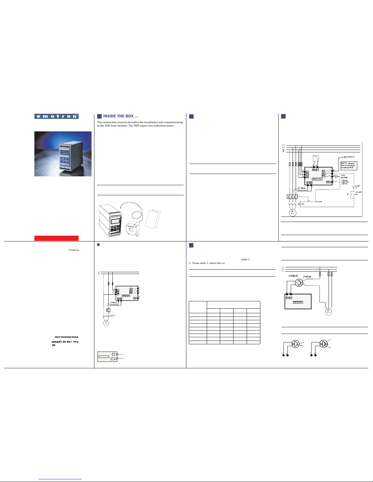
Current input Current transformer; CTM 010, 025, 050 and 100 (>100A
extra transformer needed)
Power consumption max 6 VA
Start-up delay 1-999 s
Hysteresis 0-50% of rated motor power
Response delay 0.1-90 s
Relay output 5 A/240 VAC Resistive, 1.5 A/240 VAC Pilot duty/AC12
Analog output max load 500 ohm
Digital input max 240 VAC or 48 VDC. High:>24 VAC/DC.
Low:<1 VAC/DC
Fuse max 10 A
Terminal wire size Use 75°C copper (CU) wire only. 0.2-4.0 mm2single core
(AWG12). 0.2-2.5 mm2flexible core (AWG14), stripped length
8 mm (0.32")
Terminal tightening torque 0.56-0.79 Nm (5-7 lb-in)
Accuracy ±2%, ±1 unit cos phi>0.5; excl. current transformer; +20°C
(+68°F)
Repeatability ±1 unit 24h; +20 °C (+68°F)
Temperature tolerance max 0.1%/°C
Operating temperature -20 to +50 °C (4°F to +122°F)
Storage temperate -30 to +80 °C (22°F to +176°F)
Protection class IP20
Approved to CE, cUL (UL and CSA up to 600 V)
9
115mm(4.53)
45mm (1.77)
26mm
(1.02) 35mm
(1.38)
90mm(3.54)
Reset to FACTORY DEFAULTS (Window 99)
The FACTORY DEFAULTS are reset by entering “dEF” in window 99.
If Window 99 shows “USr” it indicates that the settings have been
changed to user specific settings.
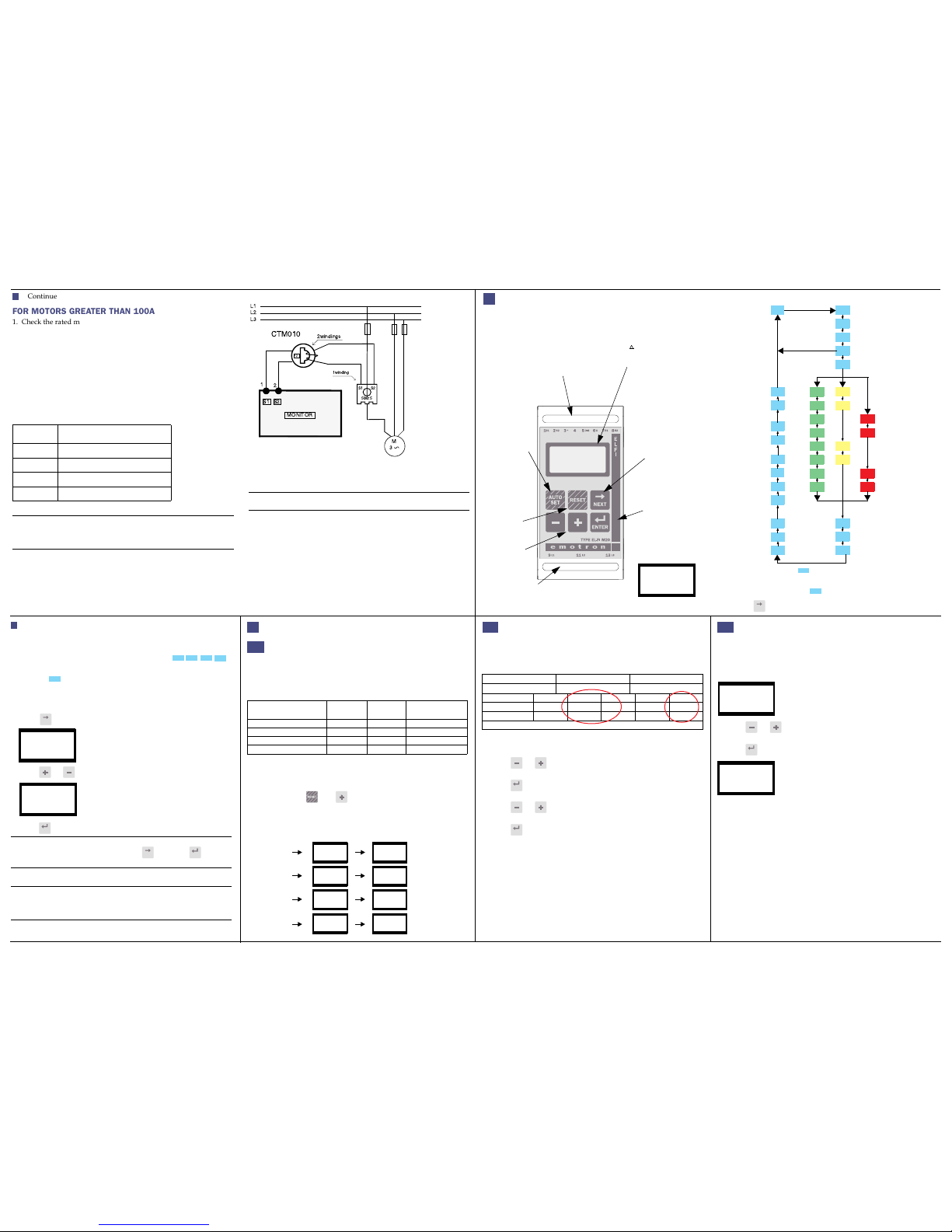
View ALARM MESSAGE (Window 00)
In an alarm condition, the window 00 appears automatically. The
window indicates the following Alarm conditions. Window 00 is
always blinking.
F
F^
LU
00
0U
00
F0
00
00
00
00
00
00
F_
FOOO
!
!
!
!
!!
!!
O
_Pre-Alarm MAX
level reached
Alarm MAX
level reached
Pre-Alarm MIN
level reached
Alarm MIN
level reached
Under voltage,
switch of f the
Over voltage,
switch of the
No motor current
Window 62=on
Out Of Range.
This message
appears only in
window 01 (actual
load) or 03 (actual
current)
supply!
supply!
Continue
Set ANALOG OUTPUT (Window 91)
The ANALOG OUTPUT provides an analog signal of either 0-20 mA
or 4-20 mA signal which represents the motor shaft power. The signal
can be inverted. Full scale: rated motor power.
Fig 12. Analog Output.
LOCK PARAMETERS (Window 04)
To avoid unintentional change of parameter settings the program-
ming can be locked by entering the code “369” in window 04. Now
only the motor variables LOAD [01], VOLTAGE [02] and CURRENT
[03] can be checked. Follow the same procedure to UNLOCK the
monitor. The AutoSet button is disabled when parameters are locked.
AutoSet via Digital Input is always active if window 81 is set to AU
(AutoSet).
Note!
The “Lock” symbol appears in all windows.
7
4.20
91
PSHAFT
100%
0%
0mA 4mA 20mA Output
20.4
20.0
0.20
4.20
24
%
01
Ï
Other manuals for EL-FI M20
1
Table of contents