manuals.online logo
Brands
  1. Home
  2. •
  3. Brands
  4. •
  5. Empire Comfort Systems
  6. •
  7. Blower
  8. •
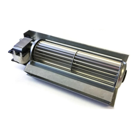
  9. Empire Comfort Systems FBB9-1 User manual

Empire Comfort Systems FBB9-1 User manual

Other Empire Comfort Systems Blower manuals

Empire Comfort Systems FBB5-1 User manual

Empire Comfort Systems

Empire Comfort Systems FBB5-1 User manual

Empire Comfort Systems FBB4 User manual

Empire Comfort Systems

Empire Comfort Systems FBB4 User manual

Empire Comfort Systems FBB21 User manual

Empire Comfort Systems

Empire Comfort Systems FBB21 User manual

Empire Comfort Systems RH-50 User manual

Empire Comfort Systems

Empire Comfort Systems RH-50 User manual

Empire Comfort Systems CIB3-2 User manual

Empire Comfort Systems

Empire Comfort Systems CIB3-2 User manual

Empire Comfort Systems FBB21 User manual

Empire Comfort Systems

Empire Comfort Systems FBB21 User manual

Popular Blower manuals by other brands

Lithium Earthwise LB20024 Operator's manual

Lithium Earthwise

Lithium Earthwise LB20024 Operator's manual

EINHELL GE-CL 36 Li E Original operating instructions

EINHELL

EINHELL GE-CL 36 Li E Original operating instructions

EINHELL VENTURRO 18/210 operating instructions

EINHELL

EINHELL VENTURRO 18/210 operating instructions

Troy-Bilt 657 Operator's manual

Troy-Bilt

Troy-Bilt 657 Operator's manual

Weed Eater VS2000BV instruction manual

Weed Eater

Weed Eater VS2000BV instruction manual

KRAUSMANN U37020-00 Operation manual

KRAUSMANN

KRAUSMANN U37020-00 Operation manual

GreenWorks Pro BLB482 Operator's manual

GreenWorks Pro

GreenWorks Pro BLB482 Operator's manual

ARIETE 2768 manual

ARIETE

ARIETE 2768 manual

NuTone 331H user guide

NuTone

NuTone 331H user guide

GÜDE GLB 200 18 Li-Ion Translation of the original instructions

GÜDE

GÜDE GLB 200 18 Li-Ion Translation of the original instructions

I.VA.CO. SC Series Operating and maintenance manual

I.VA.CO.

I.VA.CO. SC Series Operating and maintenance manual

DeWalt DCE100 instruction manual

DeWalt

DeWalt DCE100 instruction manual

Ryobi RY40404VN Operator's manual

Ryobi

Ryobi RY40404VN Operator's manual

Becker SV 7.330 operating instructions

Becker

Becker SV 7.330 operating instructions

Metabo AG 18 Pro instructions

Metabo

Metabo AG 18 Pro instructions

Desa GA3650TB installation instructions

Desa

Desa GA3650TB installation instructions

Hanseatic BVN 2500 operating instructions

Hanseatic

Hanseatic BVN 2500 operating instructions

Echo Power Blower PB-230LN Operator's manual

Echo

Echo Power Blower PB-230LN Operator's manual

manuals.online logo
manuals.online logoBrands
  • About & Mission
  • Contact us
  • Privacy Policy
  • Terms and Conditions

Copyright 2025 Manuals.Online. All Rights Reserved.

29847-5-0719 Page 1Empire Comfort Systems Inc. • Belleville, IL
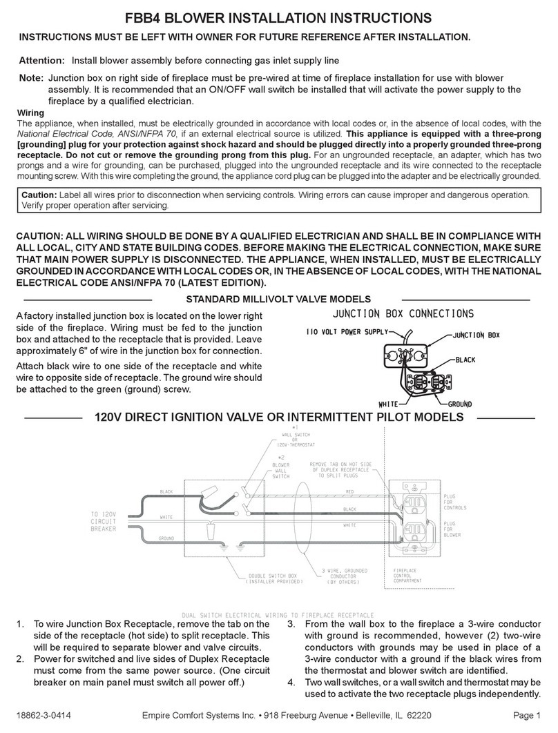
ATTENTION: Install blower assembly before connecting gas
inlet supply line
NOTE: Junction box on right side of replace must be pre-
wired at time of replace installation for use with blower
assembly. It is recommended that an ON/OFF wall switch be
installed by a qualied electrician that will activate the power
supply to the replace.
WIRING
The appliance, when installed, must be electrically grounded
in accordance with local codes or, in the absence of local
codes, with the National Electrical Code, ANSI/NFPA 70, if
an external electrical source is utilized. This appliance is
equipped with a three-prong [grounding] plug for your
protection against shock hazard and should be plugged
directly into a properly grounded three-prong receptacle.
Do not cut or remove the grounding prong from this plug.
For an ungrounded receptacle, an adapter, which has two
prongs and a wire for grounding, can be purchased, plugged
into the ungrounded receptacle and its wire connected to
the receptacle mounting screw. With this wire completing
the ground, the appliance cord plug can be plugged into the
adapter and be electrically grounded.
CAUTION
Label all wires prior to disconnection when servicing
controls. Wiring errors can cause improper and dangerous
operation. Verify proper operation after servicing.
BLOWER MOTOR
The blower motor does not have oiling holes. Do not attempt
to oil the blower motor.
BLOWER WHEELS
The blower wheels will collect lint and could require periodic
cleaning. If the air output decreases or the noise level
increases, it indicates a dirty blower wheel. Remove blower
and clean blower wheels.
WARNING
Unplugging of blower accessory will not stop the heater
from cycling. To turn off gas to the heater (millivolt model):
push in gas control knob slightly and turn clockwise to
“OFF.” Do not force. To turn off gas on direct ignition
model, turn gas line valve to “OFF.”
BLOWER INSTALLATION
WARNING
If previously installed, do not damage gas inlet supply
line when blower assembly is inserted into replace.
If necessary, removal of the gas inlet supply line may
be necessary.
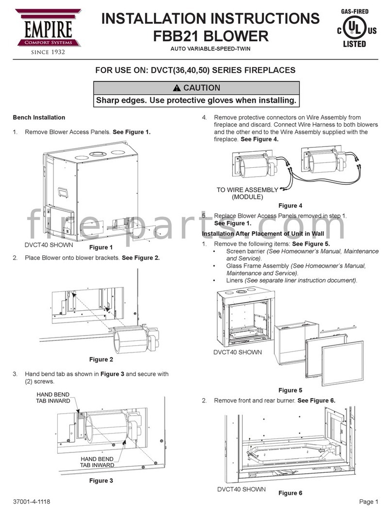
1. Remove decorative front, valve cover (three screws), and
glass door assembly.
2.
Reposition the extension module mount plate, module, and
extension module by placing them in front of the valve.
3. Insert the blower assembly past the rebox support leg
with the motor portion angled to the front of the replace.
See Figure 1. Slide the blower past the supply tubing to
position the blower along the back wall of the replace
back in the open space along the left side of the replace.
See Figure 2.
Figure 1
Figure 2
FBB9-1 BLOWER KIT
INSTALLATION INSTRUCTIONS
INSTRUCTIONS MUST BE LEFT WITH THE OWNER FOR FUTURE REFERENCE AFTER INSTALLATION.
29847-5-0719Page 2
2
1
3
4
5
ITEM NO. PART NO. DESCRIPTION
130605 Bracket, Blower
2 R12447 Blower Assembly
3R7615 Cord Set
4 R7891 Ground Wire
5R2142 #10 Screw
www.empirecomfort.com
Empire Comfort Systems Inc.
Belleville, IL
If you have a general question
about our products, please e-mail
us at [email protected].
If you have a service or repair
question, please contact your dealer.
4. Replace the extension module mount plate, module and
extension module.
5. Plug the blower into the 3-prong receptacle on the
extension module labeled “fan”. See Figure 3.
120 VOLT AC
BLOWER ASSEMBLY
POWER CORD
MODULE
SECURE GROUND TERMINAL
UNDER AVALVE MOUNTING
SCREW
Figure 3
6. Remove one of the valve mounting screws. Locate the
ground wire ring tongue terminal and secure the ground
to the valve by re-installing the valve mount screw. See
Figure 3.
7. Insert the power cord plug from the extension module into
the junction box at the right side of the replace.
8. Verify wiring connections did not get loose or disconnected
during blower installation.
9.
Replace glass door assembly, valve cover, and decorative
front.
EXPLODED VIEW AND PARTS LIST
SECURE GROUND
TERMINAL UNDER A VALVE
MOUNTING SCREW