Emriver Em2 Installation instructions

Warnings
© 2012 Little River Research & Design; updated July 2018 1
YOU MUST READ AND UNDERSTAND THESE WARNINGS
BEFORE USING THE EMRIVER MODEL
The Emriver model is very heavy when filled with water and sediment. A collapse of the
model’s supports could severely injure or kill a person. Be absolutely sure you understand
how to use the supports.
Use only the supports provided with the Emriver geomodel. Despite weight-bearing claims, no
standard production sawhorse is strong enough to safely support the model. Sawhorses and
folding tables can collapse under dynamic or side loading.
Check all fittings on the aluminum supports before each use to be sure they are secure.
When setting up the box, the supports must be laterally level and aligned. They must also be
aligned with the proper support point underneath the box. Otherwise the box could warp or
collapse when loaded.
Never set the box up on a surface with a slope exceeding 8% (a 7-inch drop in 7 feet).
Never use more than 27 gal (102 L) of water in the model. Using more than the maximum
amount of water and sediment could cause the box or supports to collapse.
Never use more than the provided 150 lb (68 kg) of sediment in the box, and do not place any
heavy objects in the box.
Never allow people to sit or stand on or in the box. Never get underneath the loaded box.
Use only the pump and power supply provided with the Emriver Em2. Be certain to connect
the power supply to a properly grounded outlet. Always use the Ground Fault Circuit
Interrupter (GFCI) provided with the Emriver model (see Figure 18), and be sure to read the
manual that accompanies the GFCI.
When using a 12-volt battery to power the model, always use the Emriver Battery Adapter
from Little River Research & Design. Never bypass the fuses.
When powering the model with a 12-volt battery, be sure you understand the dangers
associated with charging and using lead-acid batteries, and consider using safer spill-proof
batteries.
The box should only be used for its intended purpose as stated herein.
If any part of the box or pumping system is damaged, if you have any doubts about the
electrical or structural safety of the model, or if you do not understand these directions, do not
use this model.

2 © 2012 Little River Research & Design; updated July 2018
[This page was intentionally left blank.]

Introduction
© 2012 Little River Research & Design; updated July 2018 3
Introduction .................................................................................................................................................. 4
Parts and Accessories Checklist .................................................................................................................... 6
Assembly and Operation............................................................................................................................... 7
Setup checklist ............................................................................................................................................21
Disassembly, Transport and Storage .......................................................................................................... 22
Maintenance and Care…………………………………………………………………………………………………………………………..23
Demonstrations and Experiments ..............................................................................................................24
Specifications ..............................................................................................................................................26
All contents copyrighted 2012
Little River Research & Design
All rights reserved
Emriver and the meandering river
logo are registered trademarks
Introduction
4 © 2012 Little River Research & Design; updated July 2018
Introduction
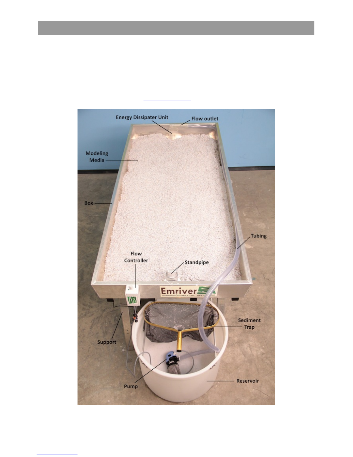
This manual describes the safe use and maintenance of your Emriver Em2 river process simulator. It is
very heavy when filled with modeling media and water, and could be dangerous if not properly
supported, assembled, and operated.
Therefore, it is important that you read, understand, and abide by all the instructions and warnings in
this manual to avoid damage to the model or personal injury. Updates to this manual and other support
for the Emriver model may be found at www.emriver.com.
Figure 1. Parts of the Emriver Em2 river process simulator. Power supply is shown in Figure 2.

Introduction
© 2012 Little River Research & Design; updated July 2018 5
Figure 2. Power supply included with the
Emriver Em2 model, shown attached to the
downstream support.

Parts and Accessories Checklist
6 © 2012 Little River Research & Design; updated July 2018
Emriver parts and accessories checklist:
Parts and Accessories Checklist
Other parts and supplies you may want to have on
hand:
Emriver Em2 Box
Modeling media in 5 buckets
Emriver Use and Care Manual
Emriver Lab Materials
Standpipe
Emriver supports
Reservoir
Sediment trap
Pump and filter
¾-inch-diameter tubing
Electronic Flow Controller
Energy Dissipater Unit (EDU)
Flow outlet
Power supply
GFCI-equipped outlet
Hydraulic shapes
Measuring tape
Solid scoop
Perforated Scoop
Riprap stones
Simulated riparian vegetation
Scrapers for moving media
Blue and green dye
Paper towels and mop
Shim materials
Hand level
Plastic buckets for sediment and water
Garden hose
Scraper/trowel
Notebook
Household bleach
Small towels for drying hands
Sieve
Laser level (for use with Scientific/Academic
Kit)
12-volt battery (for use with Emriver Battery
Adapter)
Battery charger (for use with Emriver Battery
Adapter)
Accessories available for purchase from Little River
Research & Design:
Digital Flow Controller
Emriver Battery Adapter
Structures Kit:
Box culverts
Walled culvert
Double walled culvert
Model houses
Academic Kit:
Emriver level rod and holder
Graduated cylinder (250 mL)
Graduated cylinder (1000 mL)
Graduated beaker (2000 mL)
Stopwatch
Coarse mesh hand sieve
Perforated scooper
Hand size scooper (not perforated)
Assembly and Operation
© 2012 Little River Research & Design; updated July 2018 7
Assembly and Operation
STEP 1 -Set up the supports
To assemble the model, begin by setting up the aluminum supports. The shorter support will
hold the downstream end of the box, so keep in mind how you would like the model oriented
when placing the supports.
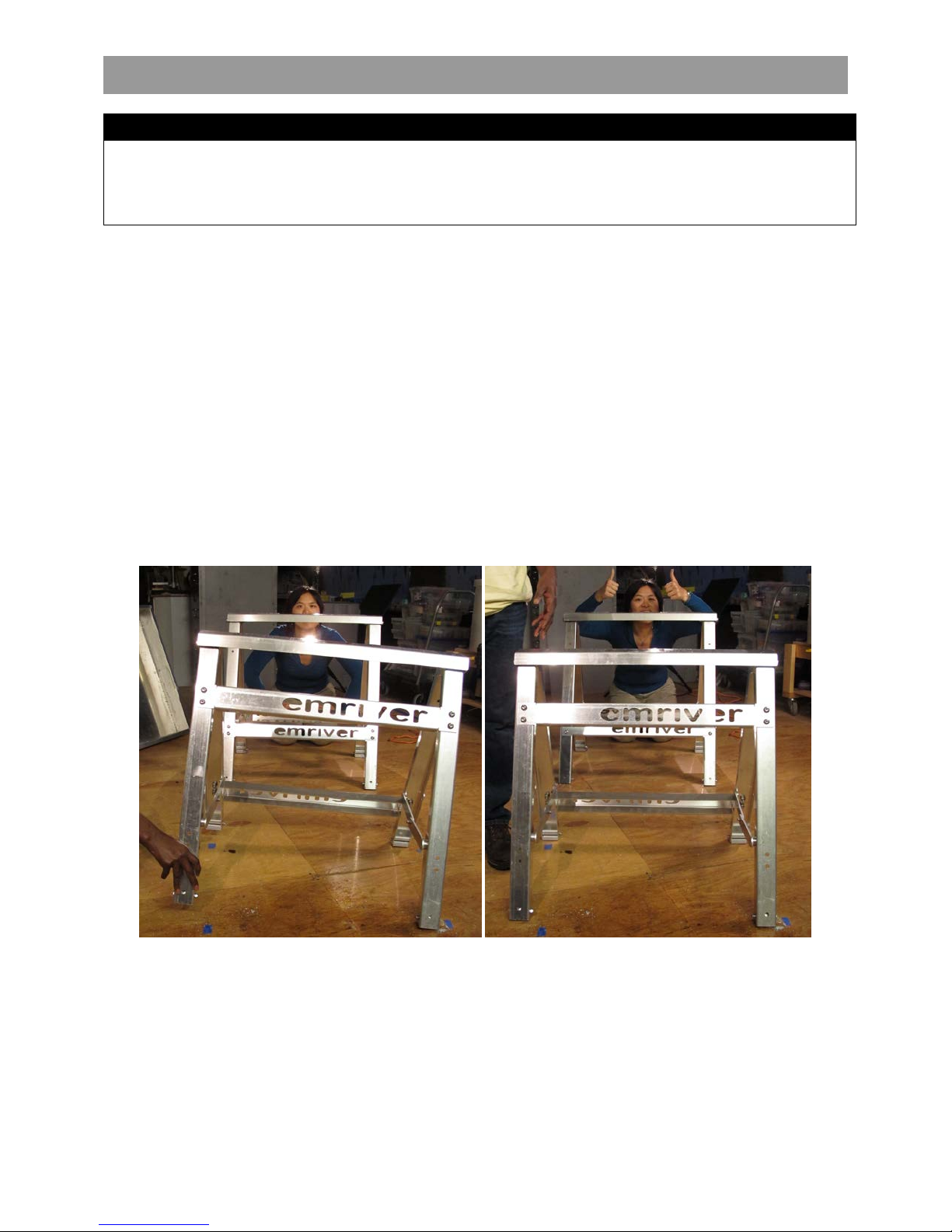
If the supports are not properly aligned, the box will twist when fully loaded, which may
damage the box. To check alignment, look across the support crossbars as shown in
Figure 3. The supports must be both level and parallel.
The supports should be set up so that the crossbars are 49 in (1.25 m) apart and aligned as
shown in Figure 3 to prevent damage to the box.
Figure 3. Incorrect (left) and correct (right) support alignment. Crossbars must be both level and
parallel when viewed as shown.
WARNING
When fully charged with water, the model can weigh in excess of 500 lb (227 kg). Dynamic loading during
use, caused by someone leaning on the model, for example, can greatly increase this load. A collapse of
the model’s supports could be dangerous and seriously damage the model. You must be certain the
model is adequately supported and that you have read and understand all warnings.

Assembly and Operation
8 © 2012 Little River Research & Design; updated July 2018
On uneven ground, use shims made from ¾-inch plywood or 2-by-4 scraps under the support
feet as necessary.
Be sure all four feet of each support are properly supported. One horse is modified to provide
clearance for the reservoir (see Figure 9). Place the supports so this opening lies at the
downstream end.
The Emriver supports have a difference in height of about 3 in (76 mm), yielding a box
slope of 6%.
The slope of channels in the box will be determined by the position of the standpipe, so
the exact box slope is not necessarily important.
Note: Labels on the supports display arrows that indicate proper placement and orientation,
with the shorter support at the geomodel’s downstream end. See Figure 4.
Figure 4. Labels on the supports indicate proper orientation, with
the shorter support at the downstream end.

Assembly and Operation
© 2012 Little River Research & Design; updated July 2018 9
STEP 2 -Install the standpipe in the drain assembly
Install the standpipe by sliding it into the drain assembly from the underside of the box. Insert
the handle first. The seal may be damaged if you insert the standpipe from above. For initial
setup, the standpipe should extend into the box approximately 2 in (50 mm).
The standpipe will move much more freely in the drain assembly seal when wet — you may
want to moisten the standpipe before inserting it.
The standpipe has been lubricated with a silicone grease to allow smooth action against the
rubber seal. This lubricant is waterproof, nontoxic, and should last for many uses. As needed,
apply a small amount to restore smooth movement. This silicone grease may be found at most
hardware stores and is typically used for waterproofing electronics and o-rings. An extra tube of
silicone grease has been provided with your model and can be found inside the red carrying
case. Keep the standpipe coated with a thin film of silicone grease to ensure years of trouble-
free operation.
The drain assembly nut should not be over tightened. Some water should leak from around
the drain assembly, down the outside of the standpipe, and into the reservoir. This flow allows
“groundwater” to exit the media and improves river modeling performance.
Figure 5. Insert the standpipe from
the underside of the box to avoid
damage to the seal. The standpipe
will move much easier when the seal
is wet. Never attempt to install the
standpipe from the top of the box.

Assembly and Operation
10 © 2012 Little River Research & Design; updated July 2018
STEP 3 -Install the box
The box MUST be supported at the two reinforced ribs, and nowhere else. See Figure 6.
Figure 6. Support ribs on the underside of the box
(indicated with arrows) are areas where the box
must be supported.
CAUTION
The supports must be properly aligned with the support ribs on the box before any weight is
added to the box. See Figure 8.

Assembly and Operation
© 2012 Little River Research & Design; updated July 2018 11
When the supports are level and aligned, place the box on them.
Note: Gaps of more than 0.25 in (6 mm) between the box’s support ribs and the support
crossbars indicate that the supports are NOT properly aligned.
Figure 7. Lift the box onto the supports. It is best to complete this
task with two people.
Figure 8. Check to ensure that the support ribs on the box rest on
the supports properly.

Assembly and Operation
12 © 2012 Little River Research & Design; updated July 2018
STEP 4 -Position the reservoir
Place the reservoir beneath the box at the downstream end. The reservoir should be located as
shown in Figure 9 so that the standpipe will drain into the reservoir. Note that the support at
the downstream end of the box has an opening for the reservoir.
Figure 9. Place the reservoir beneath the support
at the downstream end.
STEP 5 -Position the pump
Attach one end of the tubing onto the arm of the pump. Place the pump, lying on its side, in the
bottom of the reservoir, keeping the wire connectors outside of the reservoir. Check that the
filter is securely attached to the pump. Note that you may have a pump and filter that look
different than those in the photo, but the setup is the same for each.
Figure 10.Place the pump with filter in the bottom of the reservoir, lying on its side. The filter easily screws
onto the pump. The tubing is attached to the arm on the pump.

Assembly and Operation
© 2012 Little River Research & Design; updated July 2018 13
STEP 6 -Fill the reservoir
Using the graduations on the reservoir, fill it with 27 gal (102 L) of water. The reservoir is
graduated in U.S. gal. Position the reservoir before filling it with water. Do not move the
reservoir after it has been filled as this will cause damage to the reservoir. Do not fill the
reservoir with more than 27 gal (102 L) of water.
WARNING
Using more than 27 gal (102 L) of water could damage the box or cause it to collapse. Do not exceed
this volume and do not start the pump until you have filled the reservoir and carefully measured the
total volume of water in the system.
WARNING
When full of water, the reservoir weighs over 200 lb (91 kg). It will be damaged or destroyed if moved
when full.
STEP 7 -Position the sediment trap
Place the sediment trap on the aluminum struts in the reservoir. Be sure the sediment trap sits
directly below the standpipe.
Figure 11. Place the sediment trap on the aluminum struts in the
reservoir.
Assembly and Operation
14 © 2012 Little River Research & Design; updated July 2018
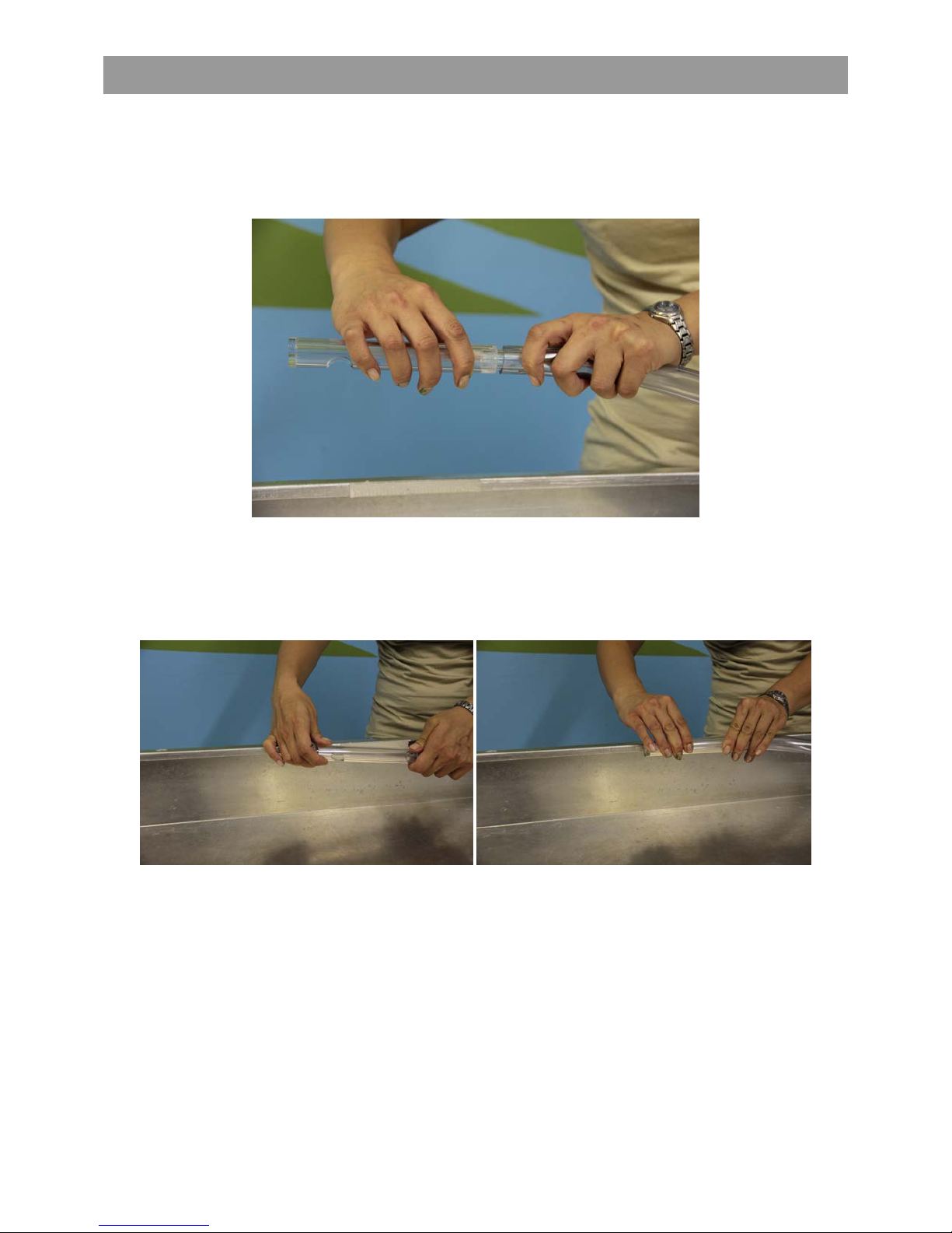
STEP 8 -Attach and position the tubing and flow outlet
Connect flow outlet to the tubing as shown below in Figure 12.
Figure 12. Insert the flow outlet into the tubing.
After the tubing is attached, align and attach the mushroom fasteners on the back of the flow
outlet to the fasteners on the inside of the box at the upstream end, as shown in Figure 13. The
outlet should snap into place.
Figure 13. Align the mushroom fasteners on the flow outlet with those on the inside of the box at the
upstream end. Snap the fasteners together to secure the outlet to the box.
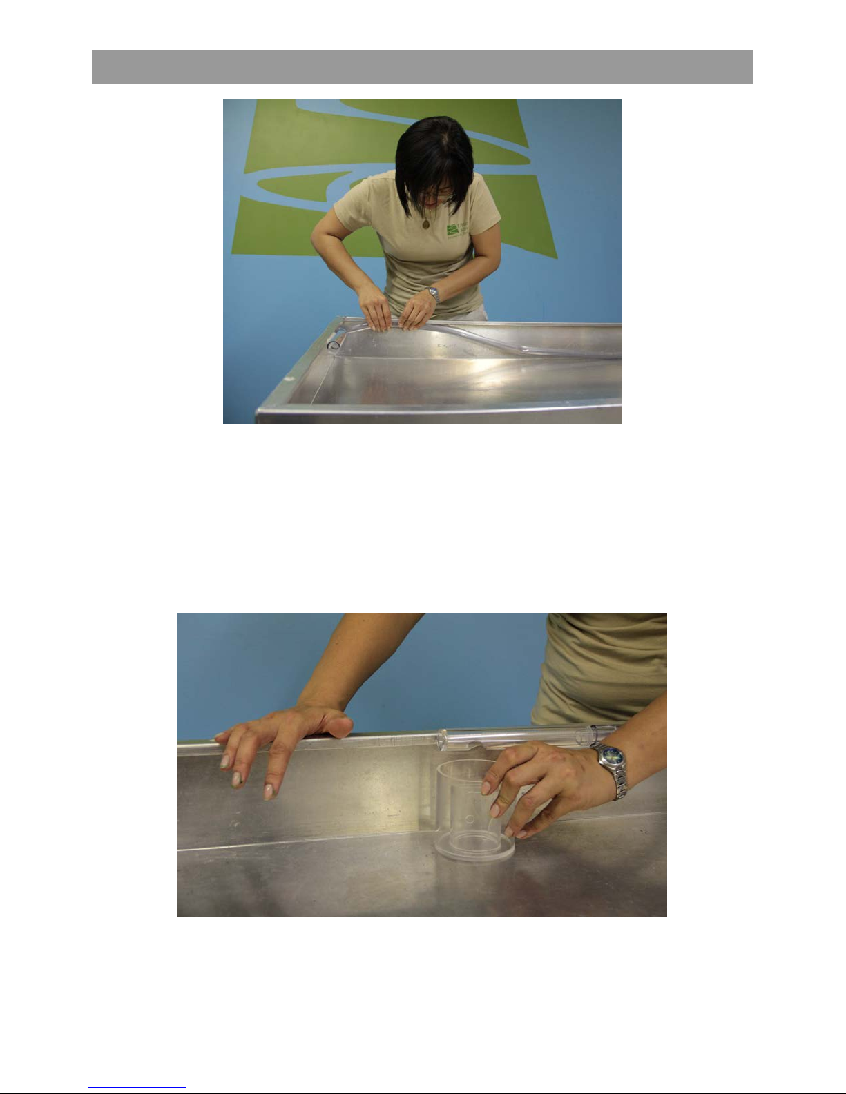
Place the tubing along the inside edge of the box, starting from the attached flow outlet. The
tubing should run out of the box and into the reservoir, where it is connected to the pump (see
Figure 1). Starting from the upstream end, roll the tubing under the lip of the box until you are
near the standpipe. This will keep the tubing from interfering with demonstrations and media
behavior. See Figure 14.
Assembly and Operation
© 2012 Little River Research & Design; updated July 2018 15
Figure 14. Tuck the tubing beneath the lip on the inside of the box.
STEP 9 -Position the Energy Dissipater Unit
Place the Energy Dissipater Unit (EDU) beneath the flow outlet. The flow outlet opening should
line up with the innermost cylinder of the EDU. The EDU’s Y-shaped opening should face
downstream. See Figure 24 for a photo of the EDU while in use.
Figure 15. Place the EDU beneath the flow outlet.

Assembly and Operation
16 © 2012 Little River Research & Design; updated July 2018
STEP 10 -Fill the box with modeling media (sediment)
Pour the media into the box one bucket at a time. Spread the media using the scraper included
with your geomodel to distribute it evenly throughout the box. See Figure 16.
Handling the media:
•During experiments and demonstrations, sediment leaving the box will accumulate in
the sediment trap. The rate at which the sediment trap fills is highly variable,
depending on activity in the box.
•When the sediment trap becomes full, use the perforated scoop included with the
Emriver model to return sediment to the box.
Allowing sediment to accumulate in the
reservoir will NOT harm the pump. The
filter is sized to allow the pump to function
normally even when completely buried in
sediment. However, fine debris such as
dirt, lint and pollen can accumulate in the
media over time and clog this filter. Just
give it a rinse now and then.
Figure 16. Pour the media into the box
Assembly and Operation
© 2012 Little River Research & Design; updated July 2018 17
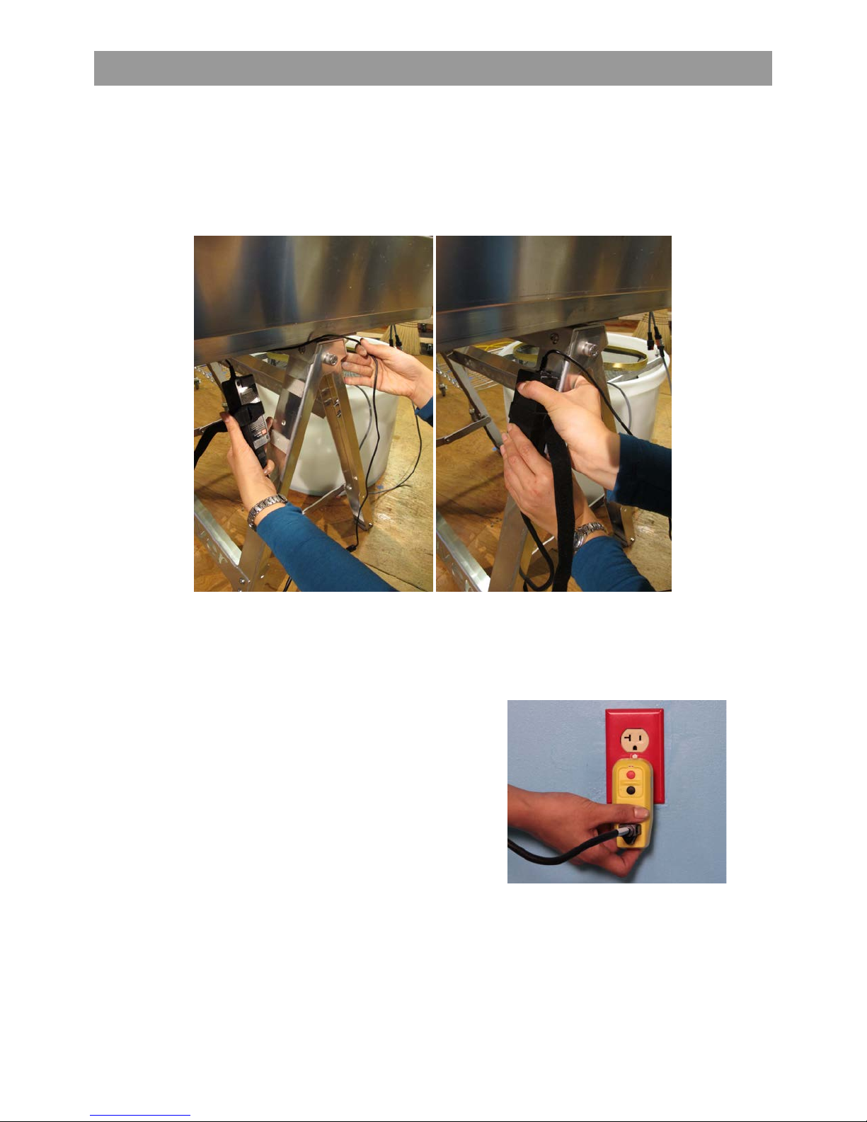
STEP 11 -Power the pump
Attach the brick power supply to the leg of the shorter support using the mushroom fasteners
on the support and the brick power supply. Wrap the Velcro® strap around the support leg and
the brick power supply to fasten securely. See Figure 17.
Figure 17. Attach the brick power supply to the leg of the downstream
support.
Connect the power cord to the Ground Fault Circuit
Interrupter (GFCI) (US users only). If you are using an
extension cord, connect the extension cord to the
GFCI. Do not plug the model's power cord directly
into a wall outlet. Always use the GFCI.
If the red indicator light on the GFCI is on, it is ready
for use and the model should be powered. If the red
indicator light is off, press the red “Reset” button.
Figure 18. Always connect the power
cord to the GFCI. Never plug the
model's power supply directly into a
wall outlet.
Assembly and Operation
18 © 2012 Little River Research & Design; updated July 2018
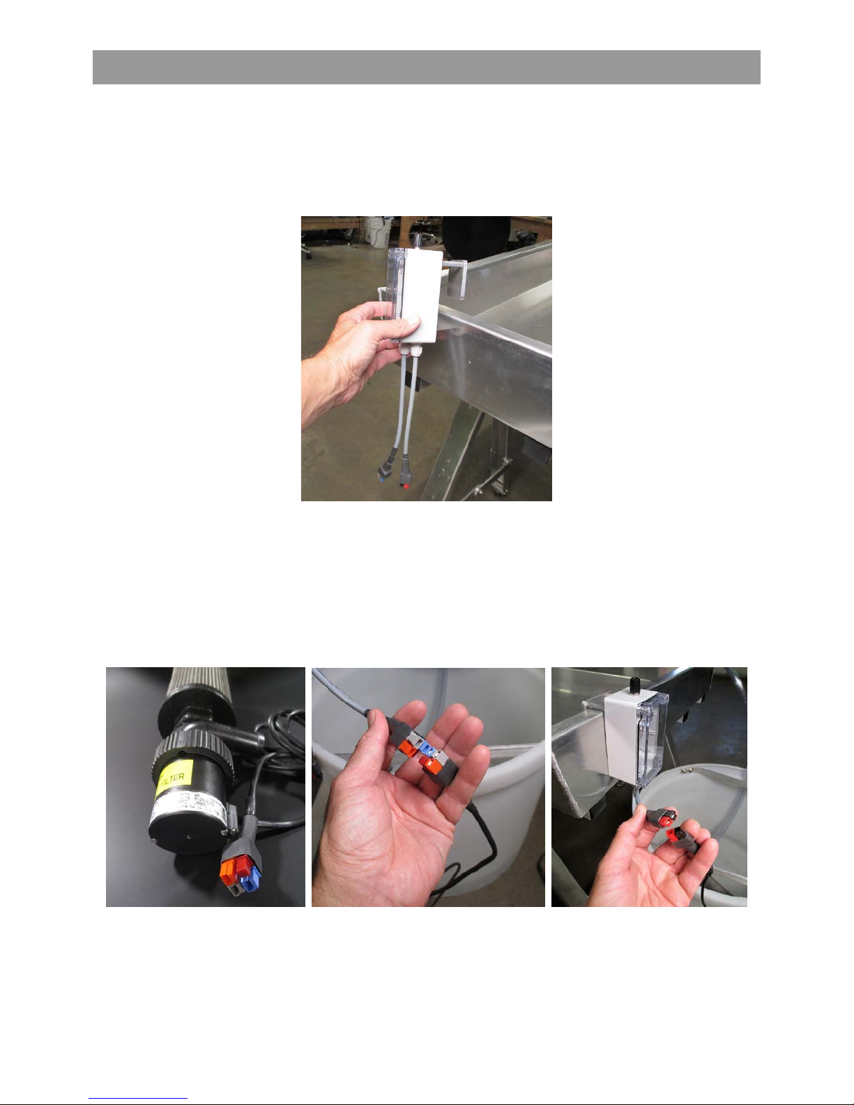
STEP 12 -Attach the Electronic Flow Controller (Model K28, or older Crayfish)
If you purchased the Digital Flow Controller (Model K500, or older Alix), see the separate
instruction sheet. Attach the flow controller to the downstream end of the box using the hook
(note that some older controllers have a Velcro connection). See Figure 19.
Figure 19. Attach the controller to the downstream end of the box.
Connect the pump to the controller using the gray, blue, and orange connectors (note there is
one red tab that is not a connector). Then, connect the controller to the power supply using the
black and red connectors. See Figure 20. Note that older models of the pump and controller
have different connectors. The older models will not work with the new models as shown here.
Simply match up the colors on the connectors.
Figure 20. The pump, at left, connects to the flow controller,
middle. The flow controller, right, connects to the power supply.
The color-coded connectors on each component will match up.

Assembly and Operation
© 2012 Little River Research & Design; updated July 2018 19
A square, green indicator light in the circuit board displays when the power is on. Change flow rate
using the knob on the controller. Pressing the knob resets the flow to zero. See Figure 21.
Troubleshooting: If the controller does not produce flow, and there are no lights on the circuit board,
check the power supply to ensure that the cord is fully connected and that there is a light on the power
brick.
If the power light is on, but there is no flow, check to see that the flow indicator LED is lit on the circuit
board (round green light). If it is lit, check the connection between the controller and the pump. Also
check for any obstructions or clogged filters. Expel all air from pump and hose. If the flow indicator LED
is not lit, adjust the knob clockwise until the LED is lit and there is flow.
Figure 21. Turn on the pump and
control flow with the knob.
Note:The knob does not turn the pump off completely; it merely stops flow. The pump is on as long as
the power is connected. To completely turn off the pump, the power must be disconnected.
Note:If the pump is reluctant to prime when started, reorient or shake it a bit (while underwater) to
remove air trapped in its intake. If necessary, clean any debris from the filter by unscrewing it from the
pump and flushing it with water.
Assembly and Operation
20 © 2012 Little River Research & Design; updated July 2018
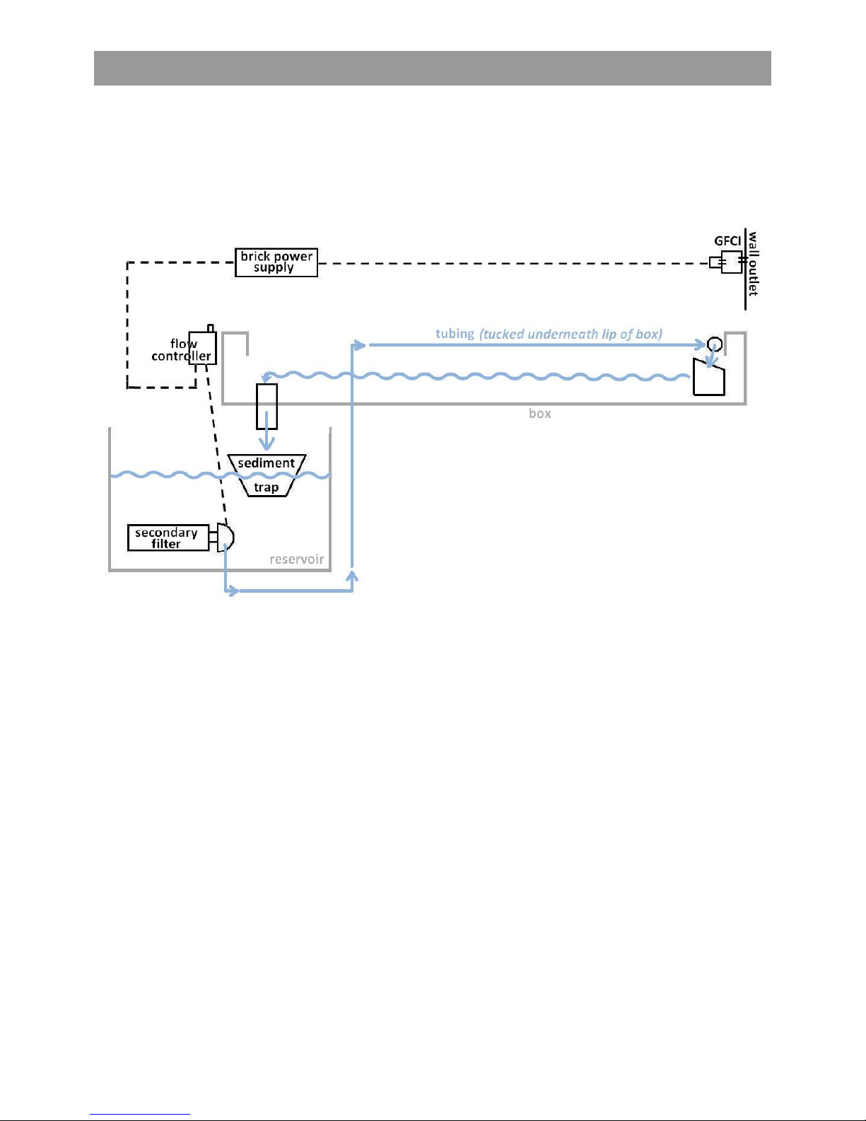
Flow Pathways
After the Emriver Em2 model has been assembled according to the instructions in this manual, it is
ready for use. Figure 22 is a conceptual chart that shows flow pathways of water and electricity through
a properly assembled Emriver Em2 model during use.
Figure 22. Flow pathways for water (solid line) and electricity (dotted line).
Table of contents


