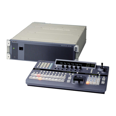
EMTEST UCS 500Mx Instruction Manual

Manual
For Operation
UCS 500Mx
The ultra-compact simulator
and its system modules
UCS 500 upgrade version
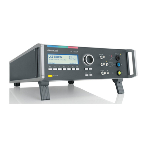
UCS 500 M4
UCS 500 M6
UCS 500 M6A
UCS500Mx - designed as a modular system - is the most
intelligent solution offering exactly what you need for full-
compliant immunity tests against transient and power fail
phenomena. The distinct operation features, convenient DUT
connection facilities, a clearly arranged menu structure and
display philosophy as well as the pre-programmed standard test
routines make testing easy, reliable and safe. Extendable by a
variety of test accessories the UCS500Mx is a universal
equipment for abroad range of recommendations even for three-
phase applications up to 100A
EN/IEC 61000-4-2
EN/IEC 61000-4-4
EN/IEC 61000-4-5
EN/IEC 61000-4-8
EN/IEC 61000-4-9
EN/IEC 61000-4-11
EN/IEC 61000-4-12
EN/IEC 61000-4-29
EN 61000-6-1
EN 61000-6-2
Version: 3.05 / 31.01.2005
emc test equipment
Replaces: 3.04 / 17.12.2004
Filename: UCS500Mx operating manual V305.doc
Printdate: 31.01.05

EM TEST UCS 500 Series
Operating Manual V 3.05 2/ 57
Contens
1. Model Overview ..............................................................................................................4
1.1. UCS Models.......................................................................................................................................4
2. Standards covered by UCS 500 M4 / M6 / M6A ............................................................ 4
3. Operating Functions.......................................................................................................5
3.1. Front view...........................................................................................................................................5
3.2. Rear view...........................................................................................................................................6
4. Operation......................................................................................................................... 9
4.1. Description of the menus ...................................................................................................................9
4.2. Menu structure...................................................................................................................................9
4.3. Main Menu........................................................................................................................................10
4.4. Service .............................................................................................................................................11
4.5. Setup................................................................................................................................................12
5. Test Equipment UCS 500 M .........................................................................................13
6. Technical data...............................................................................................................14
6.1. EFT Electrical Fast Transients Burst as per IEC 61000-4-4...............................................................14
6.2. SURGE Immunity requirements as per IEC 61000-4-5...................................................................15
6.3. Power Fail Generator as per IEC 61000-4-11 .................................................................................16
6.4. ESD as per EN 61000-4-2, EN 61000-6-1/2, IEC 61000-4-2, IEC 801-2........................................17
6.5. General Specifications.....................................................................................................................17
6.6. UCS 500 upgrade version................................................................................................................18
7. Maintenance and service .............................................................................................19
7.1. General.............................................................................................................................................19
7.2. Test set- up......................................................................................................................................19
7.3. Calibration and verification...............................................................................................................19
8. Delivery Groups............................................................................................................20
8.1. Basic equipment...............................................................................................................................20
8.2. Accessories and options..................................................................................................................20
9. EFT Burst as per IEC 61000-4-4.................................................................................. 21
9.1. Operation..........................................................................................................................................21
9.1.1. Quick Start .......................................................................................................................................21
9.1.2. Standard test routines.....................................................................................................................22
9.1.3. User Test Routines ..........................................................................................................................23
9.2. Burst generation...............................................................................................................................25
9.3. Test level with Burst as per IEC 61000-4-4 Ed.2.............................................................................25
9.4. Coupling decoupling network...........................................................................................................26
9.4.1. Coupling/decoupling network for ac/dc power lines.........................................................................26
9.4.2. Capacitive coupling clamp...............................................................................................................27
9.5. Burst Test Setup ..............................................................................................................................27
10. Surge Immunity as per IEC 61000-4-5.........................................................................28
10.1. Operation..........................................................................................................................................28
10.1.1. Quick Start .......................................................................................................................................29
10.1.2. Standard test Routine ......................................................................................................................30
10.1.3. User Test Routines ..........................................................................................................................32
10.1.4. Pulsed magnetic field as per IEC 61000-4-9 ...................................................................................33
10.1.5. Ring Wave........................................................................................................................................34
10.1.6. Setup current limiter for surge current .............................................................................................34
10.2. Surge pulse generation....................................................................................................................35
10.3. Coupling decoupling network...........................................................................................................35
10.3.1. Coupling to ac/dc power supply lines...............................................................................................35
10.3.2. Coupling to I / O lines.......................................................................................................................35
10.4. Test set-up.......................................................................................................................................35

EM TEST UCS 500 Series
Operating Manual V 3.05 3/ 57
11. Voltage Dips as per IEC 61000-4-11 ............................................................................ 36
11.1. Operation..........................................................................................................................................36
11.1.1. Quick Start .......................................................................................................................................37
11.1.2. Standard Test Routines ...................................................................................................................38
11.1.3. User test routines.............................................................................................................................41
11.2. The Power Fail Test.........................................................................................................................42
11.3. The Power Fail Test.........................................................................................................................43
11.3.1. Voltage Interruptions........................................................................................................................43
11.3.2. Voltage dips, voltage variations .......................................................................................................44
11.4. DC Power networks .........................................................................................................................44
11.5. Test setup and accessories .............................................................................................................45
11.5.1. Transformer type V4780 ..................................................................................................................45
11.5.2. Motor variac type MV 2616..............................................................................................................47
11.6. 50/60Hz Magnetic Field as per IEC 61000-4-8................................................................................49
12. Electrostatic Discharge as per IEC 61000-4-2............................................................50
12.1. Operation..........................................................................................................................................50
12.2. Quick Start .......................................................................................................................................51
12.3. Standard test routines......................................................................................................................51
12.4. ESD Generator.................................................................................................................................52
12.4.1. Test set-up according IEC 61000-4-2..............................................................................................52
12.4.2. Test application................................................................................................................................53
12.4.3. Test Level IEC 61000 - 4 - 2............................................................................................................53
12.4.4. Discharge Unit..................................................................................................................................54
13. Appendix .......................................................................................................................55
13.1. Declaration of CE-Conformity..........................................................................................................55
13.2. UCS 500 M - General Diagram........................................................................................................56
13.3. Main diagram control connection.....................................................................................................56
13.4. Main diagram high voltage connection ............................................................................................57

EM TEST UCS 500 Series
Operating Manual V 3.05 4/ 57
1. Model Overview
1.1. UCS Models
Standard models
Model Pulse voltage CDN
UCS 500 4kV 250V 16A einphasig upgrade version
UCS 500 M4 4kV 250V 16A single phase
UCS 500 M6 6kV 250V 16A single phase
UCS 500 M6A 6kV 250V 16A single phase
Special models
Special models have the index UCS500Mx Sx. The difference to the standard models are the voltage and current
ranges. The operation is the same as by the standard UCS equipment’s.
Model Pulse voltage CDN
UCS 500 M4 S1 4kV 250V 32A single phase
2. Standards covered by UCS 500 M4 / M6 / M6A
A fully equipped UCS 500M covers the following standards
- IEC 61000-4-2 ESD
- IEC 61000-4-4 Burst
- IEC 61000-4-5 Surge
- IEC 61000-4-8 50/60Hz magnetic field
- IEC 61000-4-9 Pulse magnetic field
- IEC 61000-4-11 Voltage dips
Voltage interruptions
Voltage variations for ac power mains supply
- IEC 61000-4-12 Ringwave
- IEC 61000-4-29 Voltage interruptions
Voltage dips for dc power supply systems
- ANSI Surge with 2ΩΩ couplings ( M6A only )

EM TEST UCS 500 Series
Operating Manual V 3.05 5/ 57
3. Operating Functions
3.1. Front view
1Display
2"Test On"
3Function keys "F1..F7
4Knob (Inc / Dec
5Cursor keys "←" and "→"
6Exit
7Escape
8CRO U (surge
9CRO I (surge
10 CRO trigger output ↑5V
11 HV pulse Burst output 50 Ω
12 Ground reference
13 Coupling ( burst, surge and ESD
14 Channel PF1 and PF2
15 EUT test supply
1Display
All functions and parameters are displayed (8 lines with max. 40 characters).
2Test On
By pressing the key "Test On" the test procedure is initiated with the preselected parameters. The red LED indicates the
trigger of a burst event.
3Function keys "F1 .. F7
Parameters and functions, displayed in the lowest line, can be selected with the related function key.
4Knob (Inc / Dec
The knob increments or decrements test parameters with a numeric value or selects from a list of parameters.
5Cursor keys
Parameters and functions can be changed on-line. The selection of these parameters is realized with the cursor moving to
the left or to the right.
6Exit
Pressing of the Exit function will cause a reset of the firmware. This is only possible if no test routine is running.
7ESC
When pressing the ESC button the user moves back one page in the menu.
8CRO U (surge)
At the BNC output the voltage pulse (surge) of the generator can be measured. The max. level is 10V
9CRO I (surge
At the BNC output the current pulse (surge) of the generator can be measured. The max. level is 10V
10 BNC - CRO Trigger
At the BNC output the generator trigger can be checked, e.g. the burst duration, the burst repetition rate and the spike
frequency (+15 V rectangular). This output can be generally used as oscilloscope trigger output and is synchronous to the
following events
- Burst and surge release
- Voltage dip or interruption, start of the event
- ESD contact discharge
11 HV pulse output 50
External coupling devices such as the capacitive coupling clamp and the 3-phase coupling network are connected to the
coaxial 50 ohm output. Also the calibration of the generator is handled at this output
12 Ground reference
During test or calibration procedure the burst generator must be grounded to the reference ground plane
13 Coupling mode
The actual coupling mode is indicated by LED
14 Channel PF1/PF2
This LED indicates the channel mode during the power fail test.
15 EUT test supply
For single-phase EUT the coupling/decoupling network is part of the generator. The EUT is powered via the safety banana
plugs at the front panel of the simulator

EM TEST UCS 500 Series
Operating Manual V 3.05 6/ 57
3.2. Rear view
1Test supply input; channel PF1 together with
the red lamp for phase indication
2Test supply input; channel PF2 together with
the red lamp for phase indication
3Test supply input neutral
4Test supply input PE
5Sync input
6Reference earth connection
7HV output for Surge pulse
8Common output for Surge pulse
1Test supply PF1
The phase of the power supply for the EUT is connected to the banana connector PF1. The phase L is
conducted to the EUT voltage supply via PF1 if channel PF1 is selected in the set-up menu.
To guarantee a correct function of the synchronization the phase shall be connected to this input. The red lamp
than shall be alighted
2Test supply PF2
The phase of the power supply for the EUT is connected to the banana connector PF2. This input is generally
used for voltage dip testing as per IEC 61000-4-11. At this input the reduced dip voltage is applied The phase L
is conducted to the EUT voltage supply via PF2 if channel PF2 is selected in the set-up menu. Normally a variac
is connected to PF2, e.g., 0-250V. A motor driven variac can be controlled via a 0-10V analogue control output.
To guarantee a correct function of the synchronization the phase shall be connected to this input. The red lamp
than shall be alighted
3Test supply neutral ( PF1/PF2 )
The neutral line of the power supply for the EUT is connected to the banana connector N
4Test supply PE ( PF1/PF2 )
The protective earth line of the power supply for the EUT is connected to the banana connector PE
5SYNC input
An ac voltage to which the events shall be synchronized is connected to this input. If no voltage is available the
tests are started automatically in asynchronous mode. Normally this input shall be connected directly to L of the
channel PF1. The maximum input voltage is 250Vac
6Reference earth connection
The generator has to be connected to the reference earth plane of the test set up. The connection at the rear
part of the generator is an alternative to the grounding point at the front panel
Connection EUT supply
The EUT power supply is normally connected to
the UCS plugs PF1, N and PE
A tap of a motor variac or adapting transformer for
power fail testing is connected to the connection
PF2.
The phase synchronisation SYNC must be
connected to PF1. By missing this connection all
tests runs in asynchronous mede with no phase
angle adjust for pulse release.
The earth bolt must be connected to the ground
reference.

EM TEST UCS 500 Series
Operating Manual V 3.05 7/ 57
7HV output for Surge pulse
8Common output for Surge pulse
9Ventilation
10 Warning lamp
11 External trigger
12 BNC connector MON U
13 BNC connector MON I
7HV output
The coax plug is the HV HIGH output of the simulator. It is used for external coupling/decoupling networks as
well as for the RWG 500 modules
8COM output
The Com output is the HV LOW output of the simulator. The output is floating
Attention
The direct output of the surge generator is located at the rear panel of the instrument, HV and
COM. It is not allowed to connect these outputs to any other coupling/decoupling network than
manufactured by EM TEST, e.g. the types CNV and CNI. Before to connect any external
networks to this output the operator must contact the manufacturer. Any damages due to this
matter are not covered by warranty.
The direct pulse output shall also not be used to connect the generator directly to any power
conducting lines
The waveshape measured at the direct pulse output must not be within the tolerances specified in
IEC 61000-4-5. The pulse shape shall be verified at the CDN output directly, no matter whether it
is an internal or external CDN.
9Ventilation
After long term duration tests the generator should keep on running for some minutes to cool down the system.
10 Warning lamp
A voltage free contact is available for external warning indications (warning lamp). The signal is generated after
pressing TEST ON.
11 External trigger
One single event, burst, surge, voltage dip or ESD can be released. Trigger level 5-15V positive going.
12 BNC connector MON U
At this BNC connector the output power supply voltage for the EUT can be measured. The max. level is 10V.
13 BNC connector MON I
At this BNC connector the output current for the EUT can be measured, e.g. the nominal current or the peak
inrush current. The rating is 10mV/A.

EM TEST UCS 500 Series
Operating Manual V 3.05 8/ 57
14 Control voltage 0-10V
15 Security circuit
16 Mains selector 115V / 230V
17 Power on switch
18 Fuse of the high voltage power supply
19 Serial interface RS 232
20 Parallel interface IEEE
21 Remote control connector
22 FAIL 1
23 FAIL 2
14 Mains selector
The voltage is used to control external power sources. The source is normally connected to the channel PF2
(normally a motor driven variac). The voltage level is selectable via the operating facilities of the UCS 500M. The
voltage level can also be selected within the service menu under the function „setup.
15 Safety circuit
The test can only be started if the security circuit is closed. If the circuit is opened during a running test the
simulator will be switched off immediately.
14 Mains selector
Selection of 115V / 230V
17 Power on switch
The switch is part of the mains filter. Mains fuses are part of the filter. (230V / 1A and 115V / 2A )
18 Fuse of the high voltage power supply
The high voltage power supply is protected by this fuse „F3“. In case that no high voltage is generated but the
control unit works properly this fuse shall be checked.
19 Serial interface
RS 232 interface with a 9-pole connector.
20 Parallel interface GPIB / IEEE 488
IEEE 488 interface with IEEE connector
21 Remote control connector CN
External coupling devices are controlled via this remote control connector.
22 Fail detection FAIL 1 EUT control (TEST STOP
Grounding this input will cause a complete stop of the running test procedure. (+15V to ground) The test must
be completely restarted.
23 Fail detection FAIL 2 EUT control (TEST PAUSE
Grounding this input will cause a break for the running test procedure (+15V to ground).The test will be
continued when the input is no more connected to ground.

EM TEST UCS 500 Series
Operating Manual V 3.05 9/ 57
4. Operation
4.1. Description of the menus
The simulator is operated by an easy menu control system. Seven function
keys are available to select parameters and functions.
The selected parameter is blinking and can be changed by turning the knob (incr./decr.). The digit
to be changed can be selected with the cursor (çè ).
ESC will take you back to the previous level in the menu and set the displayed values. The latest
settings are stored automatically and will be recalled when the menu is selected again.
EXIT will reset the firmware to the main screen.
All functions are indicated on the display; max. 8 lines and 40 characters.
EM TEST
UCS 500 M4
Ultra Compact Simulator
V 3.00a02
Burst
Surge
Power Fail
ESD
SWN: 001234
The serial number and the version number SWN are
used for traceability reasons. These numbers are listed
in the test reports and calibration certificates. These
numbers also are listed within the test reports
generated by the ISM ISO software.
Start-up display example UCS 500M4. The models type is displayed after startup.
4.2. Menu structure
Level 0...4
Level 0 Level 1 Level 2 Level 3 Level 4
MAIN MENU
F1 BURST IEC 61000-4-4
F2 SURGE IEC 61000-4-5/9
F3 PFS IEC61000-4-11/8/29
F4 ESD IEC 61000-4-2
F7 SERVICE
Burst IEC 61000-4-4
F1 Quick Start
F2 Standard routines
F3 User test routines
Quick Start
F1 Start
F2 Change
F3 Continue
Start
Start the test routine
Change
Select all parameters
Continue
Continue the test routine
Surge IEC 61000-4-5/9 Standard routines
Preprogrammed test routines as
per standard requirements
Standard routines
F1 : F4 IEC 61000-4-4 Level 1-4
F5 Generic Standard EN 61000-6-1
F6 Generic standard EN 61000-6-2
F7 Manual standard routine
Standard routines F1..F3
F1 Start
F2 Change
F3 Continue
Power Fail IEC 61000-4-8/11/29 User test routines
Preprogrammed test routines for
evaluation and design support
F1 Synchronous to the mains
F2 Random burst release
F3 Change V after T by ∆U
F4 Frequency sweep I
F5 Frequency sweep II
F6 Frequency sweep III
F7 Change polarity after T
User test routines F1..F3
F1 Start
F2 Change
F3 Continue
ESD IEC 61000-4-2
Service
F1 Adresses
F3 Setup
F4 Change standard levels
Setup
F1 Change language
F2 LCD backlighting
F3 Interfaces
F4 ESD/keyboard beeper
F5 Running time clock
F6 Set voltage
F7 Magnetic field factors
Change language Gern or English
LCD backlighting On, Off or Auto
Interfaces Select all parameters
ESD/keyboard beeper (on, off)
Running time clock
Display of the TEST ON time
Set voltage (ext. motor variac)
Magnetic field factors
Correctionfactors formagneticfield
antennaand currenttransformer
Change standard level Change standard level
F1 Allparameterstostandardlevel
F2 IEC 61000-4
F3 EN 61000-6-1
F4 EN 61000-6-2
Change standard levels
F1 IEC 61000-4-4 Burst
F2 IEC 61000-4-5 Surge
...

EM TEST UCS 500 Series
Operating Manual V 3.05 10 / 57
4.3. Main Menu
MAIN MENU
F1 : BURST IEC 61000-4-4
F2 : SURGE IEC 61000-4-5/9/12
F3 : POWER FAIL IEC 61000-4-11/8/29
F4 : ESD IEC 61000-4-2
F7 : Service
F1 F2 F3 F4 F5 F6 F7
F1 Burst test
With function key F1 the user can select Burst Test as per IEC 61000-4-4 . The test pulses are fast transients
with a pulse shape of 5/50ns.
Attention: The generator covers complete the new specifications given in the draft revision IEC 61000-4-4 edition 2 ( 2004). This
means a new spike frequency which is selectable between 5kHz and 100kHz. The burst duration is automatically matched
between 15ms and 0.75ms. The common mode coupling is new with all copplings at the same time.
F2 Surge test
With function key F2 the user can select Surge Test as per IEC 61000-4-5 . The test pulses are high energy
pulses with a voltage shape of 1,2/50µs and a short circuit current shape of 8/20µs.
The M6A type additionally supports coupling modes to meet the ANSI standard.
In addition the test procedure for Pulse Magnetic Field testing as per IEC 61000-4-9 and the Ring Wave Test as
per IEC 61000-4-12 or ANSI/IEEE is included in this menu.
To select the RWG option the user has to enable this menu within the service menu, under “Setup” and than “Set
Voltage”.
F3 Power Fail test
With function key F3 the user can select the Power Fail Test as per IEC 61000-4-11.
The simulator will generate voltage dips and voltage fluctuations with preselectable parameters. IEC 61000-4-11
is valid for ac power supply systems. For dc supply system in future IEC 61000-4-29 shall be recommended.
In addition the test procedure for 50/60Hz Magnetic Field Testing as per IEC 61000-4-8 is included within the
menu.
The Power fail menu includes a Voltage Variation test as per IEC 61000-4-11 as test procedure. The simulator
will generate voltage variations in the second range.
Attention: The generator covers already the new specifications given in FDIS IEC 61000-4-11 ( 2004). This means the introduction of
a new 80% test level as well as a new function for the Voltage Variation test.
F4 ESD as per IEC 61000-4-2
With function key F4 the user selects the ESD mode. In addition the ESD discharge gun shall be connected to
the rear output of the UCS.
F7 Service
Setup and servicing routines are available.

EM TEST UCS 500 Series
Operating Manual V 3.05 11 / 57
4.4. Service
SERVICE
F1 : Addresses
F3 : Set-up
F4 : Change standard levels
F7 : Status
F1 F2 F3 F4 F5 F6 F7
F1 Addresses
The addresses of the EM TEST AG and the EM TEST GmbH are shown. For all other addresses of all EM TEST
sales partners refer to
the URL www.emtest.com.
F3 Set-up
The software will clearly explain the set-up procedure.
F4 Change standard levels
F1: Set all parameters acc to standard The stored standard test levels can be changed within this menu.
The settings are actualised to the standards dated in summer 2004.
F2: IEC 61000-4
F1: IEC 61000-4-4 Burst
F2: IEC 61000-4-5 Surge
F3: IEC 61000-4-8 Magnetic field AC
F4: IEC 61000-4-9 Magnetic field Surge
F5: IEC 61000-4-11 Power Fail AC
F6: IEC 61000-4-29 Power Fail DC
F7: IEC 61000-4-2 ESD
F3: EN 61000-6-1 Generic
F1: EN 61000-6-1 Generic Burst
F2: EN 61000-6-1 Generic Surge
F3: EN 61000-6-1 Generic Power Fail
F4: EN 61000-6-2 Generic
F1: EN 61000-6-1 Generic Burst
F2: EN 61000-6-1 Generic Surge
F3: EN 61000-6-1 Generic Power Fail
F7 Status
Status information of the equipment.
Page 1 Page 2
UCS Model Built in modules Status Keyboard - Beep RS 232 Baudrate
Firmware Version Status ESD - Beep IEEE Address
Firmware Number Status Backlighting
Option Burst
Operating time DI – Status 00000 Voltage Magnetic field values
Device powered on SCR-Status 00000 V : max ext. Variac Cf :Coil factor
Testing time Vn : Nominal voltage Tf :Transformer factor
Device test time 2/2 Ch : Default channel If : Impedance factor

EM TEST UCS 500 Series
Operating Manual V 3.05 12 / 57
4.5. Setup
SETUP
F1 : Change language / Sprache ändern
F2 : LCD backlighting
F3 : Interfaces
F4 : Beep
F5 : Timer
F6 : Set voltage
F7 : Magnetic field correction factors
F1 F2 F3 F4 F5 F6 F7
F1 Change language
The user can chose between two languages, German and English.
F2 LCD backlighting
With the use of F2 the backlighting can be switched on or off.
Additionally the Auto Off function can be programmed to switch off the backlighting after a defined time that the
equipment has not been in operation (1 - 30minBecause of the limited lifetime of LCD displays, approx. 10,000h
this function should always be activated.
F3 Interfaces
This menu will help the user to define the status of the integrated serial and parallel interfaces, e.g. the baud rate
of the RS 232 or the address of the IEEE interface.
F4 Beep
F1 is the selector for the keyboard beeper ON/OFF mode. (Short beep at every keyboard hit)
F3 is the selector for the ESD-beeper ON/OFF mode. (Short beep at releasing an ESD pulse)
To indicate that a running test is finished the beeper sounds allways 3 times (not changeable).
F5 Operating time
Pressing of F5 will show the different operating time and status of the test equipment.
Operating time : Total time where the UCS is powered on.
Testing Time : Total time during a running test.
DI – Status : Service information about internal digital inputs.
SCR – Status : Service information about surge switch operation
F6 Set voltage
For control of an external power supply source an analogue control voltage can be programmed (0-10V dc).
The operator can specify the following parameters:
F1: Max. variac voltage V [ V ] Maximal output voltage at 100% position of the external motor variac or dc
controlled voltage source. The analogue reference value for the max. voltage is 10V.
F2: Mains supply voltage V [ V ] of the device under test. This voltage shall be specified by the operator and
depends on the type of equipment under test. The variac normally is automatically set to this output voltage.
F3: Default channel. The operator select the default channel PF1 or PF2 from which the EUT is powered.
F4: Ring Wave. For RWG testing the operator can select between two different modules:
-No module ( the RWG operation within the Surge menu is not available ).
-M4 module up to max 4000V
-M6 module up to max 6000V
F7 Magnetic field correction factors
F1 : Coil factor Af [A/m]Range [ 0.20...9.99 step 0.01 ]
F2 : Transformer factor Tf [A/V]Range [ 0.020...9.999 step 0.001 ]
F3 : Impedance factor If [A/V]Range [ 0.20...1.00 step 0.01 ]
These values are delivered together with the necessary options to conducted magnetic field testing.
-Coil factor depends on the type of antenna which is used for the test.
-Transformer factor depends on the type of transformer which is used for the test.
-Impedance factor depends on the type of surge generator which is used for the test. A generator with a
source impedance of 2Ωneeds an impedance factor of approx. If = 0.5

EM TEST UCS 500 Series
Operating Manual V 3.05 13 / 57
5. Test Equipment UCS 500 M
The simulator UCS 500M is separated in differents main parts. Each functional part is sep separately-held
mounted. The control unit is screened to all other parts.
1
2
3
7
5
6
Front panel
Back panel
20
4
16
16
19
19
6
18
9
10
11
13
15
17
14
14
821 22
23
21
12
Control unit
1Power supply board
2Interface board
3Controller board
4Power supply transformer
5Filter board / connecting board
6Keyboard / LCD- display
7General power supply input, filter
8Ventilation
High voltage unit
9High voltage power supply
10 Storage capacitor
11 HV- board
12 ESD controller board
13 Surge switch-board
14 Coupling capacitors for surge mode
15 High voltage switch for burst mode
16 Power switches for voltage dip mode PF1, PF2
17 Current sensor
Coupling/decoupling unit
18 Filter board
19 Decoupling chokes
20 Coupling/decoupling network
21 Measuring and control output
22 Input for the power mains supply of the EUT
23 Output for the EUT supply

EM TEST UCS 500 Series
Operating Manual V 3.05 14 / 57
6. Technical data
6.1. EFT Electrical Fast Transients Burst as per IEC 61000-4-4
Test Level M4 Type, UCS 500 upgrade M6/M6A Type
Open circuit * 200V - 4400V ± 10% 200V – 5500V ± 10%
Wave shape into a 50Ωload 100V – 2200V 100V – 2750V
Rise time tr 5ns ± 30% 5ns ± 30%
Pulse duration td 50ns ±30% 50ns ±30%
Wave shape into a 1000Ωload 200V – 4400V 200V – 5500V
Rise time tr 5ns ± 30% 5ns ± 30%
Pulse duration td 35ns - 150ns 35ns - 150ns
Source impedance Zq = 50Ω± 20% Zq = 50Ω± 20%
Polarity Positive / negative positive / negative
Trigger
Trigger of bursts AUTO, MANUAL, EXTERN
Synchronization 0° - 360°
Burst duration td 0.10ms - 999.9ms
Burst repetition rate tr 10ms - 9999ms
Spike frequency f 0.1kHz – 1000kHz Range Step
< 10 kHz 0.1 kHz
10 – 100 kHz 1.0 kHz
100 – 250 kHz 10.0 kHz
> 250 kHz 50.0 kHz
Test duration T 0:01 min - 99:59 min
Output
Direct via 50Ωcoaxial connector To connect ext. coupling devices
Coupling network To L, N, PE all combinations
DUT power mains supply AC 250 V / 16 A / 50/60 Hz
DC 250V/10A
Test routines
Quick Start Immediate start, all parameters adjustable during a running test
Standard test as per IEC 61000-4-4 level 1
IEC 61000-4-4 level 2
IEC 61000-4-4 level 3
IEC 61000-4-4 level 4
EN 61000-6-1 Generic
EN 61000-6-2 Generic
IEC 61000- 4-4 Manual operated standard test routine
User test routines Synchronous burst release
Random burst release
Change level V after T by steps of dV
Frequency sweep in one single burst
Frequency sweep with constant pulses
Frequency sweep, constant burst duration
Change polarity after T
* With Burst pulses as per. IEC 61000-4-4 Ed2 : 2004 the max. output voltage can be limited.

EM TEST UCS 500 Series
Operating Manual V 3.05 15 / 57
6.2. SURGE Immunity requirements as per IEC 61000-4-5
Test level M4, UCS 500 upgrade M6/M6A
Open circuit voltage 160V - 4000V ± 10% 250V - 6600V ± 10%
Wave shape
Rise time tr 1,0 ± 30% 1,0 ± 30%
Pulse duration 50µs ± 20% 50µs ± 20%
Short circuit current 80A - 2000A ± 10% 125A - 3300A ± 10%
Wave shape
Rise time tr 6.4 ± 20% 6.4 ± 20%
Pulse duration 16µs ± 20% 16µs ± 20%
Polarity Pos., Neg., Alt Pos., Neg., Alt
Repetition rate max. 1Hz (1s* - 999s) max. 0.5Hz (2s* - 999s)
Events preselection 1 - 30'000 or endless 1 - 30'000 or endless
Counter 1 - 1000000 1 - 1000000
Trigger
Trigger of pulses AUTO, MAN, EXTERN AUTO, MAN, EXTERN
Synchronization 0 - 360° 0 - 360°
Resolution 1° 1°
Measurements
CRO 5V Trigger 5V Trigger
CRO Û 10Vp at 4kV 10Vp at 6.6kV
CRO Î 10Vp at 2kA 10Vp at 3.3kA
Peak voltmeter 4000V 6600V
Peak current meter 2000A 3300A
Output M4 M6 M6A
Direct HV-coaxial connector; Zi = 2ΩX
HV-Banana connector, Zi = 2ΩX X
Coupling network L – N with Z = 2ΩX X X
L-PE, N-PE, L+N-PE with Z = 12ΩX X X
L-PE, N-PE, L+N-PE with Z = 2ΩX
DUT supply AC 250V / 16A / 50/60 Hz X X X
DC 250V / 10A X X X
Test routines
Quick Start Immediate start, all parameters adjustable during a running test
Standard test routines as per IEC 61000-4-5 level 1
IEC 61000-4-5 level 2
IEC 61000-4-5 level 3
IEC 61000-4-5 level 4
EN 61000-6-1 Generic
EN 61000-6-2 Generic
IEC 61000-4-5 Manual operated standard routine
User test routines Change polarity after n pulses
Change coupling mode after n pulses
Change voltage level V after n pulses by ∆V
Change phase angle A after n pulses by ∆A
Magnetic field test test routine as per IEC 61000-4-9
test level 100, 300 and 1000A/m
cont. adjustable within Quick Start

EM TEST UCS 500 Series
Operating Manual V 3.05 16 / 57
6.3. Power Fail Generator as per IEC 61000-4-11
EUT supply
Channel PF1 and PF2
AC voltage/current max. 250V/16A
Mains frequency 50/60 Hz
DC voltage/current max. 250V/16A
Inrush current more than 500A
Protection Electronic fuse for continuos overcurrent / inrush currents
Electronic control of overheating
PF1 and PF2 are safe against short circuit
Trigger
Events trigger AUTO, MAN, EXTERN
Repetition rate 0.01 - 99s
Synchronization 0° - 360°
Resolution 1°
Duration of events 100µs - 9900ms
Measurements
DUT supply AC/DC voltage in the LCD display
BNC output MON U Measurement of the EUT supply
BNC output MON I divider ratio 1:100 +/- 10%
Measurement of the EUT current and the
inrush current 10mV/A, max. 1000A
CRO TRIGGER positive going flank
0-10V Control Output 0-10V DC for external voltage source
Test routines
Quick Start Immediate start, all parameters adjustable during a running test
Standard test routines as per IEC 61000-4-11 ac power ports
as per IEC 61000-4-29 dc power ports
as per IEC 61000-6-1 Generic
as per IEC 61000-6-2 Generic
Manual operated standard test routine
User test routines Voltage variation, external variac control
Change phase angle W after n events by dW
Change events duration td after n events by dtd
Inverse mode
Magnetic field test test routine according to IEC 61000-4-8
test level 1, 3, 10 and 30A/m with MC 2630 and a variac
test level 100, 300 and 1000A/m with MC26100
Magnetic field tests per IEC 61000-4-8 and -9
The test routines for handling the magnetic field tests are included in the internal UCS 500M firmware. All functions to
control external options as voltage/current sources or magnetic field antennas are included. In addition the following
hardware is required:
Option required for Magnetic Field Test per IEC 61000-4-9
- Magnetic field antenna (square 1mx1m coil MS 100)
- Adapter for connecting the square coil to the surge output.
Option required for Magnetic Field Test 50/60Hz per IEC 61000-4-8
- External variac (MV2616) and magnetic field antenna (square 1mx1m coil MS 100)
- External current transformer (MC2630) to test 1, 3, 10 and 30A/m levels
- External current transformer (MC26100) to test level 100, 300 and 1000A/m levels (short term).

EM TEST UCS 500 Series
Operating Manual V 3.05 17 / 57
6.4. ESD as per EN 61000-4-2, EN 61000-6-1/2, IEC 61000-4-2, IEC 801-2
Air discharge mode
Discharge unit type P18
Test voltage 1 – 16.5kV
Discharge capacitor 150pF ±10%
Discharge resistor 330Ω±10%
Polarity positive/negative
Holding time > 5s
Contact discharge mode
Discharge unit type P18
Test voltage 1 - 8kV
Discharge capacitor 150pF ±10%
Discharge resistor 330Ω±10%
Polarity positive/negative
Trigger
Single Single discharge
Continue Multiple discharges, controlled by the operator
Auto Automatic discharge controlled by the mainframe
Repetition rate max 10Hz, free selectable
Discharge mode Air- or contact discharge selectable
Preselector counter Preselection of the desired numbers of discharges
Beeper ON/Off acoustical signal at each discharge
Contact discharge and single air discharges
Test routines
Quick Start Immediate start, all parameters adjustable during a running test
Standard Test Routine as per IEC 61000-4-2
Rise time of the discharge current 0.7ns - 1.0ns
Test voltage First peak value Current at 30ns Current at 60ns
2 kV 7.5 A 4.0 A 2.0 A
4 kV 15.0 A 8.0 A 4.0 A
6 kV 22.5 A 12.0 A 6.0 A
8 kV 30.0 A 16.0 A 8.0 A
Ipk
10%
90%
tr
t
I 30ns I 60ns
6.5. General Specifications
Mains supply 230V/115V, 50/60Hz
Power consumption 110W
Fuse 230V : 2 AT slow blow
115V : 4 AT slow blow
Safety
Safety circuit External interlock capability
Warning lamp voltage free contact max. 250V 5A
Design per IEC 1010, EN 61010
Interfaces
Serial RS 232 1200 - 19200 Baud
Parallel IEEE Address 1-31
Analog output 0-10V DC, to control an external power supply
Dimensions 19" / 3 HU
Weight app. 25 kg
=> Not relevant data for the standards can be changed by the manufacturer <=

EM TEST UCS 500 Series
Operating Manual V 3.05 18 / 57
6.6. UCS 500 upgrade version
Upgraded UCS 500 have the same specifications as UCS 500 M4 exception the following items.
Warning lamp
The warning lamp connection is not potential free like the other UCS models. The power
supply is delivered by the internal 24V supply.
EM Test recommends to use a relays for control the external powered warning lamps.
Voltage : 24V dc
Max. load : 200mA
Synchonisation
The phase synchronisation is refered to the default channel.
ESD Option
Construction-conditioned the ESD option is not retrofitable.
Inrush current
The upgrade version has no inrush current function.

EM TEST UCS 500 Series
Operating Manual V 3.05 19 / 57
7. Maintenance and service
7.1. General
The generator is absolutely maintenance-free by using a solid state semiconductor switch to generate transients
7.2. Test set- up
When setting up the test national and international regulations
regarding human safety have to be guaranteed.
It is recommended to connect the simulator to the ground reference
plane of the test set-up.
The generators of the series 500, UCS, VCS, CSS, TSS and CNI, can
be linked together to a fully automotive test set-up.
The set-up communicates via the IEEE / GPIB bus and is controlled by
ISMIEC software. For setting up the system see the following figures:
Each generator can be operated individual as a single equipment.
7.3. Calibration and verification
The EM Test equipment are calibrated in the factory and marked with a
calibration-tag. The measuring instrument is traceable to the Swiss Federal
Office of Metrology.
The calibration date is marked. The validity of the calibration is in the area of
responsibility of the users quality system. Example: EM Test calibration-tag
Please refer to the corresponding standard before proceed a calibration or verification. The standard describes
the procedure, the tolerances and the necessary auxiliary means. There are suitable calibrations adapters to use.
All calibrations and verifications are always without mains supply voltage on the impulse- or coupling network
output.
Danger
Before starting the calibration or verification
remove the EUT Mains Supply
from the generator and from the coupling network

EM TEST UCS 500 Series
Operating Manual V 3.05 20 / 57
8. Delivery Groups
8.1. Basic equipment
•Generator type UCS 500M4/M6/M6A with recommended modules ( Burst, Surge, Power Fail, ESD)
•Mains cable
•Mains cable for the EUT supply
•Adapter for power cable
•Manual
•Calibration certificate
8.2. Accessories and options
Burst
-Capacitive coupling clamp as per IEC 61000-4-4 to couple the fast transients to signal and data lines
-ITP immunity test set for radiation
-50 Ωmatching resistor with integrated attenuator (1:100) type KW 50
-1000 Ωmatching resistor with integrated attenuator(1:1000) type KW 1000
-Attenuator 6 dB / 50 Ω
Surge
-Coupling/decoupling network as per IEC 61000-4-5 for signal lines type CNV 504/508 (4 wires and 8 wires)
-3 phase CNV 503 up to 100A
Power Fail
-Transformer type V4780
-Variac MV 2616
Magnetic field
-Magnetic field antenna MS 100
-Current transformer MC 2630 up to 30A/m
-Current transformer MC 26100 up to 1000A/m
ESD
-Vertical coupling plate type VCP
-Grounding set type EAS 30
-Test table PRT
General for Burst and Surge
-External coupling/decoupling network 3 - phase CNI 503
-EUT mains supply 400 V rms max. // 480V for USA
-Nominal current In = 16 A / 32A / 63A / 100 A rms
-Frequency 50/60 Hz
-Coupling to all lines, N, PE
-50ΩBurst output The coupling will be controlled by the UCS 500 or EFT 500
-Output for Surge coupling to other coupling networks as CNV types ...
Software "ISM_IEC"
-Test and documentation under Windows (see separate documentation)
This manual suits for next models
4
Other EMTEST Switch manuals
