EMX Industries Brite-X 100 User manual
B
Br
ri
it
te
e.
.X
X
1
10
00
0
B
Br
ri
ig
gh
ht
tn
ne
es
ss
s
s
se
en
ns
so
or
r
Operating Instructions
Brite-X 100 Operating Instructions 2
Document no. 10040204
CAUTIONS AND WARNINGS
WARNING:
1. The Brite-X is not intended for use in personal safety applications.
2. The Brite -X is not an explosion-proof enclosure. Do not use in an environment where flammable materials are
present.
3. The Brite -X sensor uses a high intensity, blue LED, do not look directly into this light source.
CAUTION: The discrete output must not be connected to outputs from other sensors (i.e.
outputs from multiple sensors must not be connected in parallel). Parallel
connections may damage sensor output circuitry.
IMPORTANT:
This product is an accessory or part of a system. Always read and follow the manufacturer’s
instructions for the equipment before connecting this product. Comply with all applicable codes
and safety regulations. Failure to do so may result in damage, injury or death.
CERTIFICATIONS: CE, CSA, UL

Brite-X 100 Operating Instructions 3
Document no. 10040204
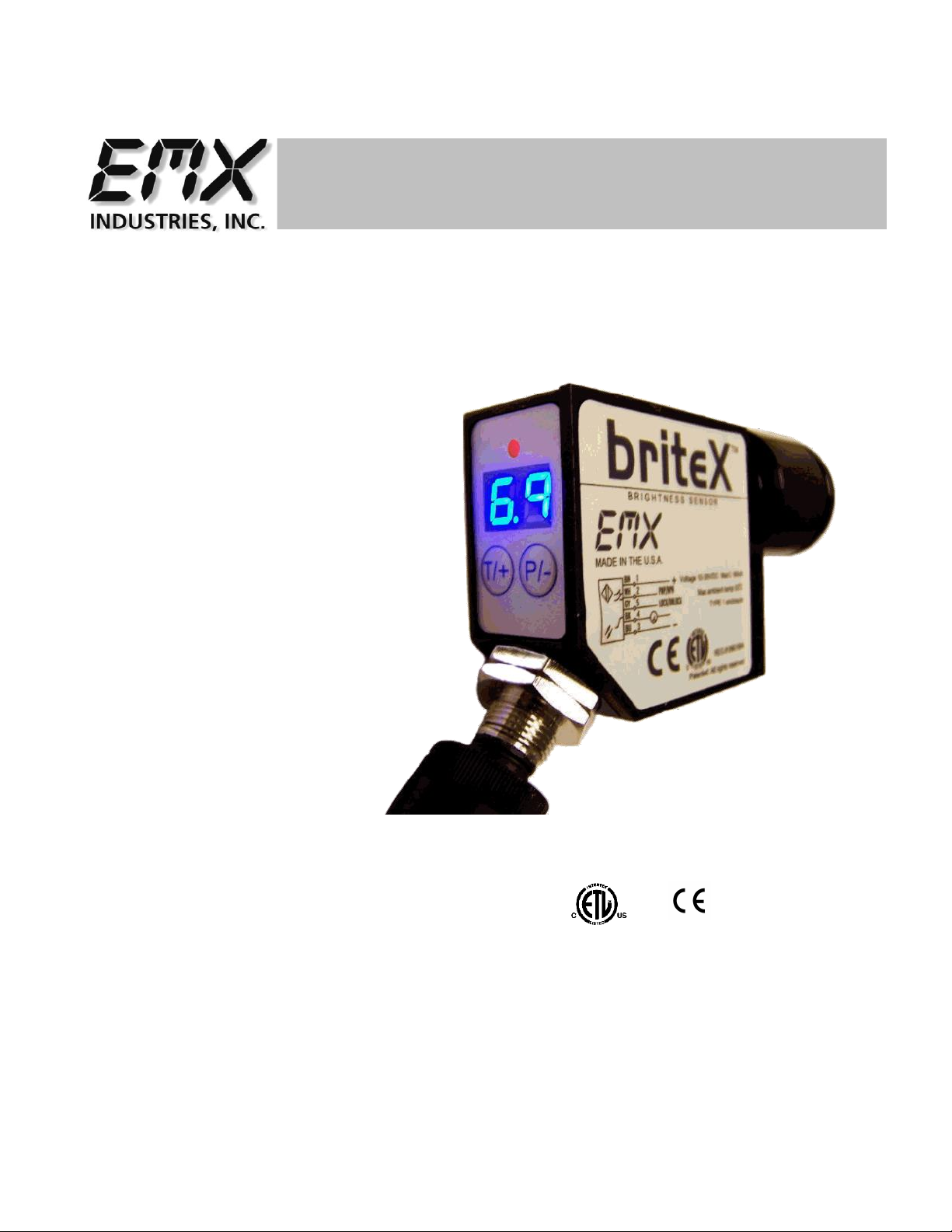
PRODUCT OVERVIEW
Brite-X 100 sensor was designed to measure the relative brightness of various materials. The brightness
is a reflectance factor of diffused blue light (457nm) as defined by ISO 2470. Brite-X 1000 uses a blue
LED to emit modulated light that is projected on to a test surface. This light is then reflected back to
the Brite-X 100 optics and measured by the sensor software.
The output is provided as an analog, 0 –5 V signal with high, 20mV resolution. A PLC or a computer can
process the analog output, or the reflected level can be set on the Brite-X 100 to trigger a discrete
output.
The Brite-X 100 is a compact sensor with a range of operation of up to 6 inches. Two seven segment
displays provide visual representation of the relative brightness from 00 to 99. Easy, five step sensitivity,
and 3 LED intensity settings provide for flexible operation over wide range of distances and materials.
Specifications
Blue Light source
457nm LED, min.100,000 hours
LED Intensity
3 levels
Relative Brightness Display Range
00 to 99
Sensitivity
X1, X2, X3, X4, X5
Detection Range
Up to 6” (150mm)
Switching Frequency
5 kHz
Brightness level
Two 7 segment digits
Brightness threshold
Two 7 segment digits
Analog Output
0 –5 V (20mV resolution)
Digital Output
Auto-Detect PNP / NPN
Extend Output Pulse
0 - 90 mS (10 steps)
Output Function
NO/NC selectable
On/Off Delay
<200 uS
Detect indicator
Red LED
Programming indicator
Yellow LED
Data retention
EEPROM non—volatile memory
Dimensions
2” (51mm) x 4” (100mm) x 1” (25mm)
Weight
.26 lbs. (117g)
Supply Voltage
10…24 VDC
Operating Current
60 mA
Short Circuit Protection
Yes (Outputs)
Overload / Reverse Polarity Protection
Yes (Supply Voltage)
Operating temperature
-20ºC…55ºC
Storage temperature
-20ºC…70ºC
Housing
Metal alloy
Mechanical protection
IP65 NOT FOR PRESSURE WASHDOWN
Connector
M12 5 pin

Brite-X 100 Operating Instructions 4
Document no. 10040204
QUICK START GUIDE
1. The display range is 00 through 99. The decimal points indicate the LED intensity level. The RED
LED above the display indicates that the intensity level exceeds the threshold setting.
2. Connect cable to power supply observing correct polarity. Reference wiring diagram.
3. Apply power; sensor will initialize and perform its power up sequence.
4. The relative intensity will be displayed. By aiming the sensor away from any objects the display
will indicate 00. Aim the sensor at a white piece of paper and the display will indicate an
intensity measurement. Move the paper further away from the sensor to decrease the intensity
level.
5. Press and release either key located below the display to view the current gain setting. R1
indicates a gain of 1; R2 indicates a gain of 2 and so on through R5. After several seconds the
sensor will return to the normal intensity display mode. While the current gain setting is shown
on the display, press the + or –key to increase or decrease the setting, then wait for the sensor to
return to the normal intensity display mode.
6. User programmable parameters are discussed in detail in the following sections.
Operation
Power up
Upon power up, the sensor initializes by turning on all segments on the display and sequencing
through red, amber and green on the status LED located above the display.
Intensity display mode
During normal operation the sensor display will indicate the relative intensity of a target within its
field of view. The range of the relative intensity display is 00 through 99.
The decimal points on the display indicate the LED output intensity. No decimal points indicate
low, one decimal point indicates medium and two decimal points indicate high intensity.
Gain Adjustment (R)
Press and release either key located below the display to view the current gain setting. R1
indicates a gain of 1; R2 indicates a gain of 2 and so on through R5. After selecting the desired
gain wait several seconds and the sensor will return to the normal intensity display mode. While
the current gain is shown on the display, press the + or –key to increase or decrease the setting,
then wait for the sensor to return to the normal intensity display mode. The selected gain is
stored in memory and is retained when power is removed.

Brite-X 100 Operating Instructions 5
Document no. 10040204
Programmable Parameters
All adjustments made to these parameters are stored in memory and are retained when power is
removed. To enter programming mode press and hold the P/-key for several seconds, the current
threshold setting will be displayed. Press and release the P/- key to scroll through the various settings.
Press and release the T/+ key to change a particular setting. Press and hold the P/-for several seconds
to return to the normal intensity display mode. The user programmable items are described below.
Threshold
When the relative intensity level exceeds the threshold setting the red status LED will turn on and
the discrete output will activate, indicating detection of the target. When the relative intensity
level drops below the threshold (as determined by the hysteresis setting), the red LED will
extinguish and the discrete output will de-activate. The threshold setting allows the user to
select the detection level. The default setting is 15.
To adjust the threshold, enter programming mode, press and hold the P/-key for several seconds,
the current threshold setting will be displayed. Press and release the T/+ key to increase the
threshold level, to decrease the threshold level, continue to hold the T/+ key until the value
approaches 99 then wraps around to 00.
LED Intensity Level (U)
The LED intensity is indicated on the display as U1, U2 and U3 for low, medium and high intensity.
Press and release the T/+ key to toggle through the 3 intensity levels. The default setting is U2,
medium intensity.
Hysteresis Level (H)
The hysteresis setting is indicated by H0 through H9. The hysteresis level is how far below the
threshold the signal must fall to de-activate or un-detect. The hysteresis can be set from 0 to 9.
For example, if the threshold is set at 25 and the intensity exceeds 25, the sensor will detect and
activate its output. With the hysteresis set to 5, the signal must drop to 20 to un-detect. This
feature is useful in cases where there may be variation within a target that might cause the
intensity to drop below the threshold slightly; the hysteresis allows the output to remain activated
until the level drops significantly. Press and release the T/+ key to change the hysteresis setting.
The default setting is 2.
Discrete Output Configuration
This setting allows the user to select either normal open (no) or normally closed (nc)
configuration. The normally open configuration de-activates the output during normal un-detect
operation, and activates the output upon detect. The normally closed configuration activates the
output during normal un-detect operation, and de-activates the output upon detect. Press and
release the T/+ key to toggle through the selections. Default is normally open.
Extend Output Pulse (P)
This feature allows extending the minimum length of time that the discrete output remains active
following target detection. The sensor response can be in the 100uS (microsecond) range, i.e. a
target can move through the sensing range in 100uS and the discrete output would active for only
that duration. A slower acquisition system (PLC) may not sample its inputs at a fast enough rate
to capture the signal. The discrete output pulse can be extended from 0 to 90mS (milliseconds) in
10 mS increments as indicated by P0 though P9 on the display. Press and release the T/+ key to
toggle through the selections.

Brite-X 100 Operating Instructions 6
Document no. 10040204
Null Offset (nu)
The null feature allows the sensor to be “zeroed”. For example, when the target is not in view
and there is a background that causes a reading above zero, the null feature allows this level to
be subtracted out, allowing the display to indicate 00. Press and hold the T/+ key to null the
sensor. The display will flash the value that is being subtracted. To set the sensor back to a true
zero, aim the sensor away from any target and repeat the null process.
Teach Function
The teach function allows the user to set the threshold by placing a representative target located
at the required distance and allowing the sensor to determine the optimum LED intensity and
setting of the threshold level.
1. Press and hold the T/+ key for several seconds until the yellow led flashes.
2. Place the target at the appropriate distance from the sensor and press the P/- key. The
display will flash 3 times and the sensor will adjust the LED intensity level to achieve
reasonable signal level. The green LED will flash.
3. Remove the target and press the P/- key. The display will flash 3 times.
4. Exit the teach function and return to the normal operating mode by Pressing the T/+ key
for several seconds.
When in the teach mode the LED flashes constantly, yellow, green or red. Yellow indicates that
the sensor is ready to be taught the Detect level. Green indicates that the sensor is ready to be
taught the Undetect level. Red indicates that the last attempt to teach resulted in an error. If
the error occurred during the teaching of the Detect level then the signal intensity was less than
01. If the error occurred during the teaching of the Undetect level, then the signal intensity was
greater than or equal to the threshold level. In either case, repeat the teach function to properly
set the levels.
Output Signals
Discrete Output
The discrete output is a PNP/NPN configuration allowing the user to provide a load on this output
that is either pulled high to VDC or low to ground. The sensor monitors this level and
automatically determines whether to operate the PNP/NPN driver. This output is typically
connected to a PLC. The output remains active as long as the intensity level exceeds the
threshold, in high-speed applications it may be useful to use the Extend Output Pulse feature to
lengthen the signal duration to meet acquisition requirements of the PLC.
CAUTION: The discrete output must not be connected to outputs from other sensors (i.e.
outputs from multiple sensors must not be connected in parallel). Parallel
connections may damage sensor output circuitry.
Analog Output
The analog output is 0-5V with 20mV resolution (8-bit). Any standard analog input channel
typically available on a PLC may monitor this output. The analog output signal is useful in
applications where simply triggering on the threshold is insufficient. For example, constant real-
time monitoring of intensity in process allows minor fluctuations or trends to be detected
permitting corrective action to be taken. In applications where minor differences in color are to
be detected, variations in brightness producing discernable level changes in the analog output can
be used to differentiate between similar colors.
Brite-X 100 Operating Instructions 7
Document no. 10040204
P/-
T/+
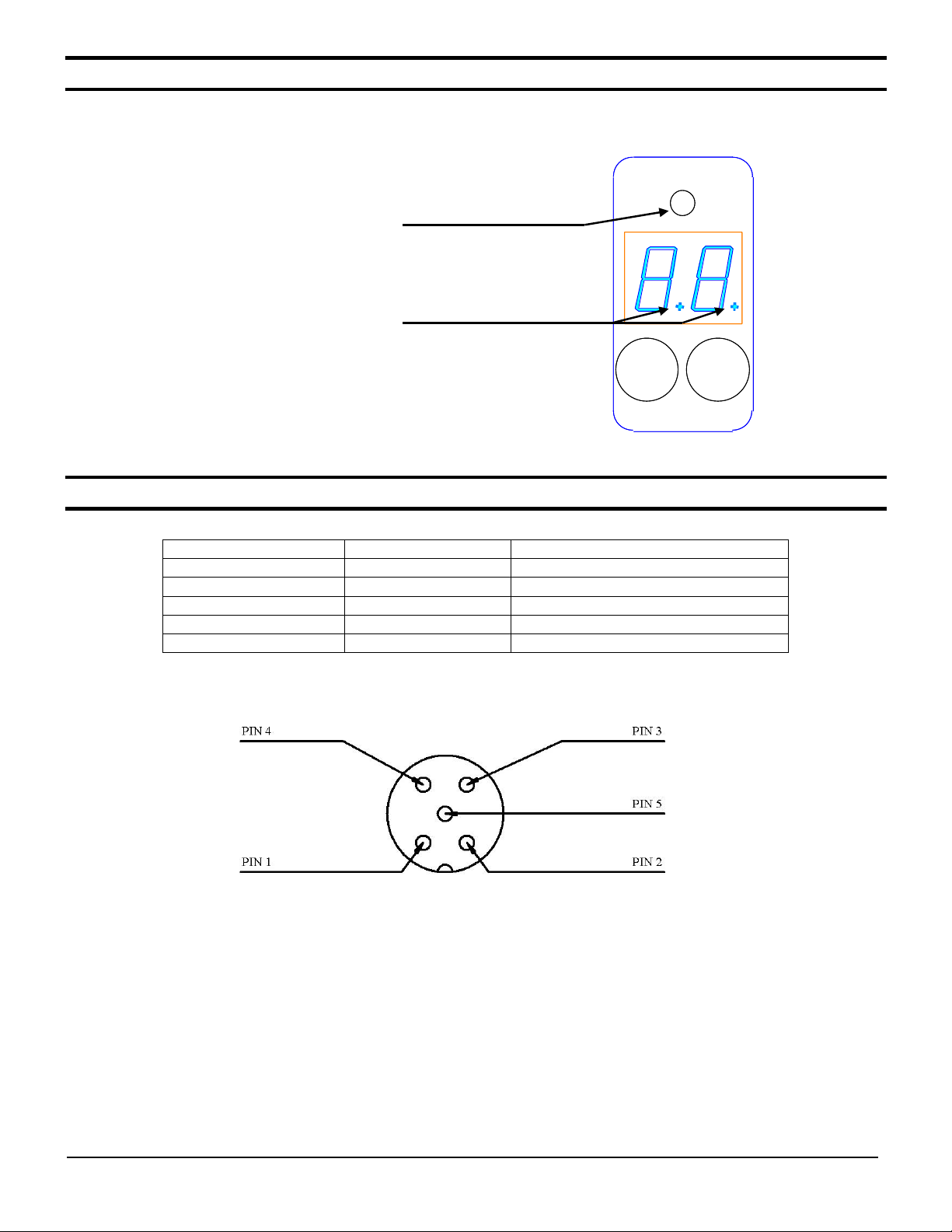
Display Indicators
Indicators
•Green LED Threshold Mode while in Undetect
•Red LED Detect
•Yellow LED Threshold Mode while in Detect
Display decimal points
•None illuminated, LED low intensity
•One illuminated, LED medium intensity
•Two illuminated, LED high intensity
M12 connector pin assignments
M12 Connector
Wire Color
Description
Pin 1
Brown
Power 10 to 24VDC
Pin 2
White
Discrete output, PNP/NPN, NO/NC
Pin 3
Blue
Ground
Pin 4
Black
Analog output 0 to 5V DC
Pin 5
Yellow
Not used

Brite-X 100 Operating Instructions 8
Document no. 10040204
Ordering information
Brite-X 100 Brightness sensor
Accessories
UVX300-BRKT UVX 300-C
Bracket 5-meter cable with M12
5 pin connector
Dimensional Details
3.70
(94.0 mm)
0.219
0.919
Ø0.175
0.000
0.625
0.150
0.650
8-32 UNC
1.2
2.45
(62.3 mm)
0.800
(20.3 mm)
Brite-X 100 Operating Instructions 9
Document no. 10040204
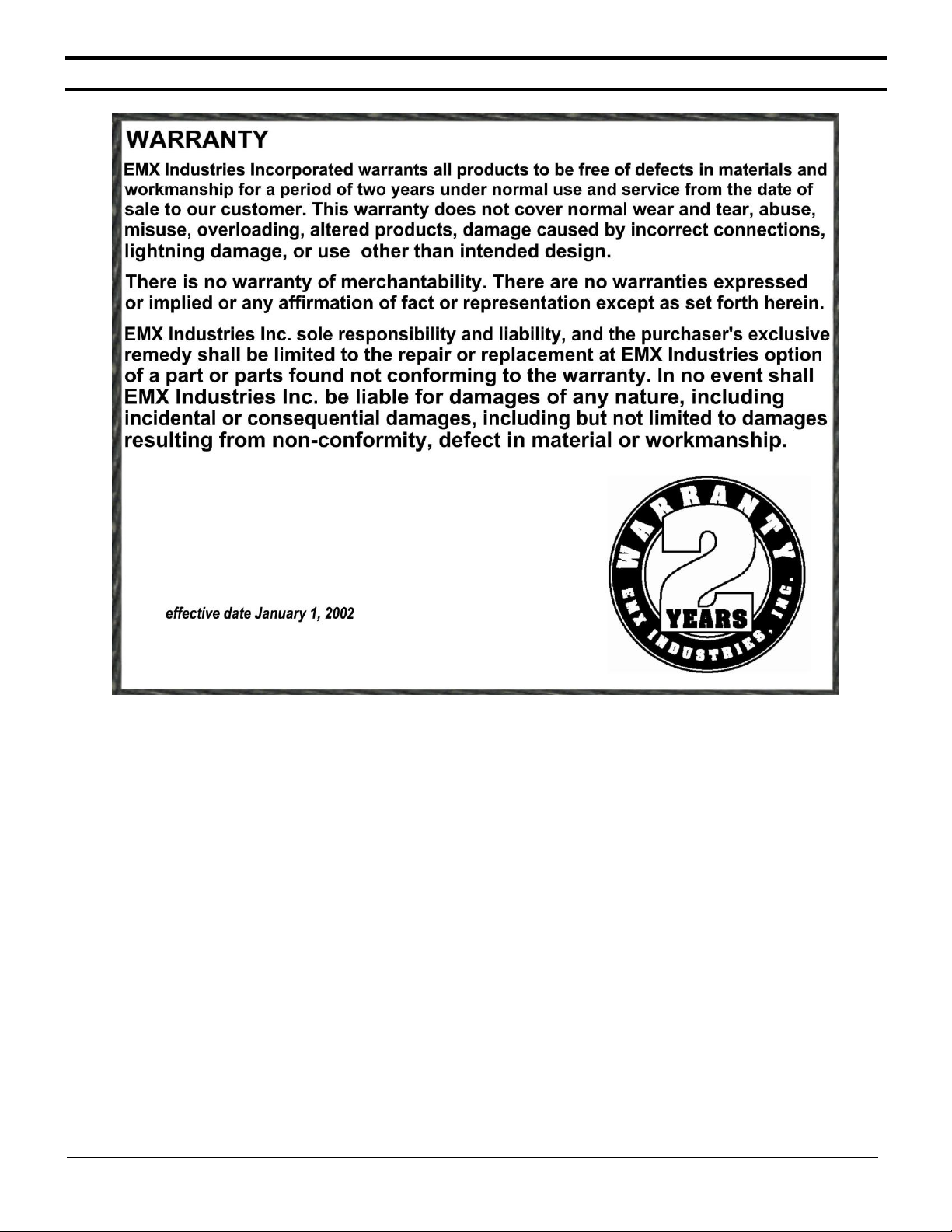
Warranty

Brite-X 100 Operating Instructions 10
Document no. 10040204
BLANK PAGE

Brite-X 100 Operating Instructions 11
Document no. 10040204
BLANK PAGE

Brite-X 100 Operating Instructions 12
Document no. 10040204
4564 Johnston Parkway
Cleveland, Ohio 44128
United States of America
WEB http://www.emxinc.com
Technical Support: (216) 834-0761
E-mail: [email protected]
Sales: (216) 518-9888
Fax (216) 518-9884
E-mail [email protected]
Revision 1.4
7.29.13
Table of contents
Other EMX Industries Measuring Instrument manuals

Popular Measuring Instrument manuals by other brands


Rayleigh Instruments
Rayleigh Instruments RI-F300 manual

Axon
Axon Synapse 2GM100 Installation and operation manual

Rice Lake
Rice Lake MASTER Bulkslide Operation manual

Endress+Hauser
Endress+Hauser Levelflex FMP53 operating instructions

Greenlee
Greenlee 200EP-G instruction manual

AR
AR Arrim ONE user manual


