Enapter Electrolyser 4.0 User manual

VERSION
DOCUMENT TITLE
RELEASE DATE
01
EL 4.0 –Battery Limits
2022-10-24
EL –Battery Limits –Rev.01 –September 2022II
Battery Limits
Electrolyser 4.0
Please study these battery limits carefully before unpacking, installing, and operating the device.
Rev. 01 –October 2022

VERSION
DOCUMENT TITLE
RELEASE DATE
01
EL 4.0 –Battery Limits
2022-10-24
EL –Battery Limits –Rev.01 –September 2022III
PREFACE
Thank you for choosing Enapter. Please study these battery limits carefully before unpacking, installing,
and operating the device.
If you have any further questions, please contact the Enapter customer support team. Quote the device
serial number and hardware number on the back of the device to help identifying your product quickly.
ENAPTER SRL
Headquarter: Via di Lavoria 56/G
56040 Crespina (PI) –Italy
T.: +39 050 644 281
E.: support@enapter.com
Website: www.enapter.com
VAT no. 13404981006
SCOPE OF THE DOCUMENT
This document must be read and understood in addition to the owner’s manual which is also available
on handbook.enapter.com. Reading this document does not replace the intensive studying of the
owner’s manual.
The purpose of this document is to define and describe the battery limits of the Electrolyser 4.0. It
illustrates the physical interface ports of the device, to allow the operator to integrate it with the other
equipment that composes his system.
This document applies to all Enapter devices with the following product code: ELE4005XXXXXSV00
APPROVED USE
This device must only be operated for its intended purpose, according to the specifications and
instructions provided in the owner’s manual. This document is intended as ancillary information only.
Keep this document in a safe place and readily available. It is the operator’s responsibility to ensure
that an installed device is always in proper conditions. Please observe any additional local requirements
applicable to the installation and operation of the device.
Improper use of the device can result in serious injuries and damage to the
environment.
Always use the device according to the specifications described in this document.
Ensure that this document is always accessible.
Make sure you have read and understood this document in its entirety.
Comply with all safety instructions and warnings.

VERSION
DOCUMENT TITLE
RELEASE DATE
01
EL 4.0 –Battery Limits
2022-10-24
EL –Battery Limits –Rev.01 –September 2022IV
Store this document and other documentation in a safe and accessible place and
pass them on to future owners and operators of the device.
Comply with all relevant local safety guidelines, rules, directives, and regulations.
Enapter is not guaranteeing efficiency, safety, and functionality in case of
modifications not described in this document.
Enapter is not responsible for any damage caused by the device or to the device
based on wrong operation or setup.
TERMS
The following terms are used in this document:
Device: Device means the unit, including its hardware and software as well as contained materials
and substances. It also includes directly attached tubes, pipes, and other equipment from Enapter
if not stated differently.
System: System means the combination of devices, tubes, pipes, and equipment from Enapter and
other manufacturers which are connected physically, logically or in any other way to produce, store,
use, transfer or convert hydrogen and related substances.
Operator: The operator is the responsible person in charge who operates, installs, connects,
maintains, and/or owns the device, its subcomponents, and additional components. To simplify
reading, this document only refers to the operator to distinguish from Enapter but may also include
the user, customer, client, owner, installer, instructor, system integrator or persons who are
responsible for a safe operation of the device.

VERSION
DOCUMENT TITLE
RELEASE DATE
01
EL 4.0 –Battery Limits
2022-10-24
EL –Battery Limits –Rev.01 –September 2022V
TABLE OF CONTENTS
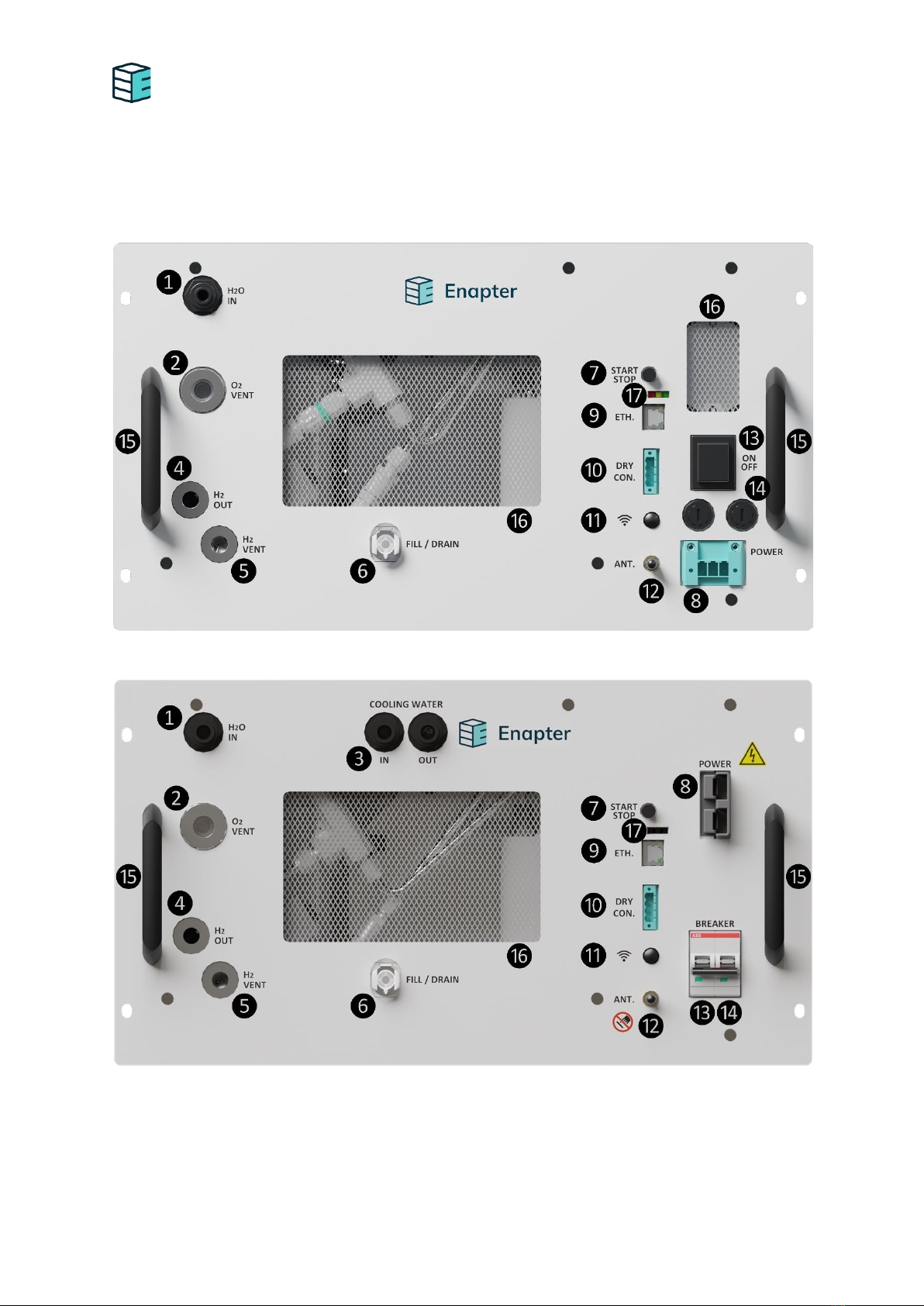
1.Device Interfaces ................................................................................................................ 7
2.Interfaces specifications...................................................................................................... 9
2.1 H2O IN................................................................................................................................ 9
2.2 O2 VENT............................................................................................................................. 9
2.3 COOLING WATER IN / OUT................................................................................................ 10
2.4 H2 OUT ............................................................................................................................ 10
2.5 H2 VENT........................................................................................................................... 11
2.6 FILL / DRAIN ..................................................................................................................... 11
2.7 START / STOP ................................................................................................................... 12
2.8 POWER............................................................................................................................. 12
2.9 ETHERNET ........................................................................................................................ 12
2.10 DRY CON .......................................................................................................................... 12
2.11 WiFi BUTTON ................................................................................................................... 13
2.12 ANTENNA......................................................................................................................... 13
2.13 ON/OFF BUTTON / BREAKER............................................................................................. 13
2.14 FUSES............................................................................................................................... 13
2.15 HANDLE BAR .................................................................................................................... 13
2.16 FRONT MESH.................................................................................................................... 13
2.17 LED .................................................................................................................................. 13
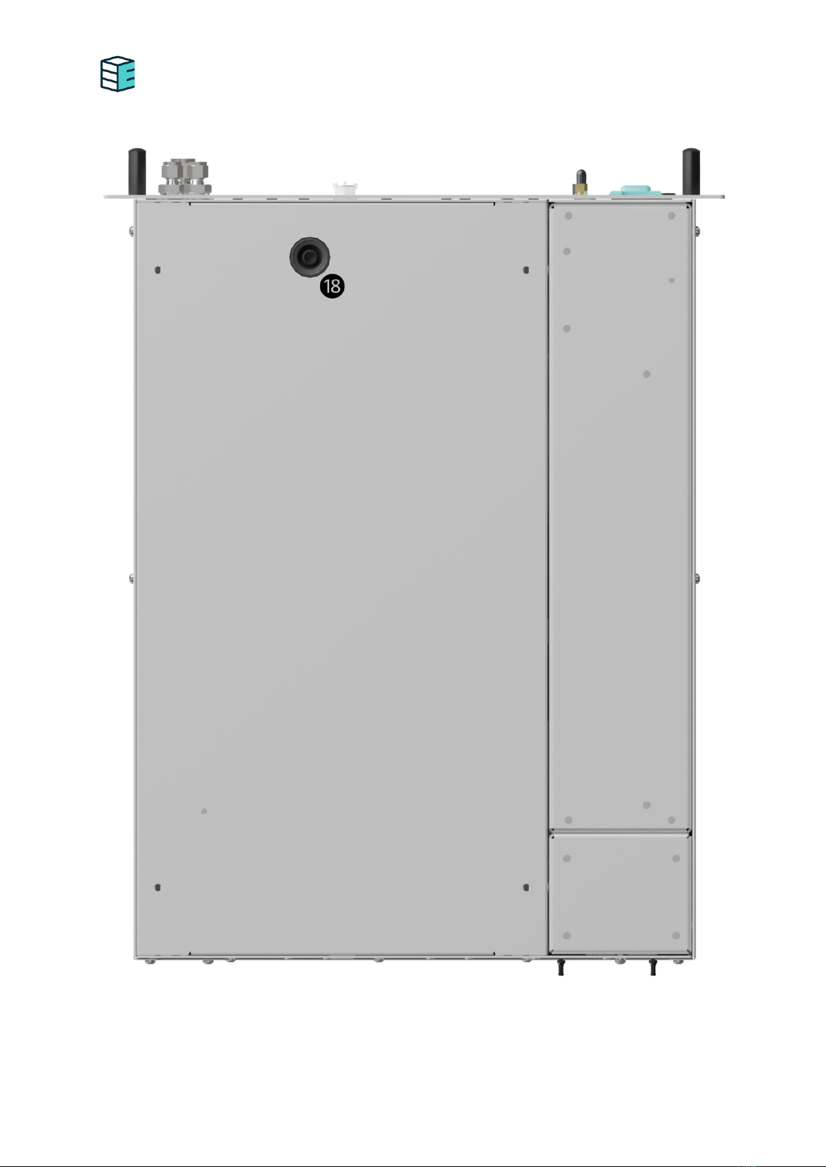
2.18 LEAKAGE DRAIN HOLE ...................................................................................................... 13

VERSION
DOCUMENT TITLE
RELEASE DATE
01
EL 4.0 –Battery Limits
2022-10-24
EL –Battery Limits –Rev.01 –September 20226
1. DEVICE INTERFACES
The following figure shows the position of the EL4.0’s physical interfaces.
EL4.0 air cooled AC version front view
EL4.0 liquid cooled DC version front view

VERSION
DOCUMENT TITLE
RELEASE DATE
01
EL 4.0 –Battery Limits
2022-10-24
EL –Battery Limits –Rev.01 –September 20227
EL4.0 bottom view

VERSION
DOCUMENT TITLE
RELEASE DATE
01
EL 4.0 –Battery Limits
2022-10-24
EL –Battery Limits –Rev.01 –September 20228
2. INTERFACES SPECIFICATIONS
The interfaces described in the following refer to the figures above. Not meeting these requirements
may result in a higher degradation and damages to the device. The requirements in this document must
always be met. However, this document does not contain the complete list of requirements for each
interface. For more information, please refer to the owner’s manual.
2.1 H2O IN
This inlet port is used for the automatic refilling of highly purified, demineralised water for the
electrolysis process.
Name
H2O IN
Direction
Pressurised input
Fitting Type
10 mm push-fit female bulkhead connector
Fitting Material
POM (Polyoxymethylene)
Fluid
Demineralised water (<20µS/cm at 25 °C)
<5 µS/cm at 25 °C recommended
Flowrate
Refilling speed up to 4 l/min periodically,
0.42 l/h water consumption in average
Pressure
1-4 barg
Temperature
5-55 °C
Make sure to not exceed the stated limits, especially do not exceed the maximum inlet
pressure.
2.2 O2 VENT
This outlet port is directly connected to the electrolyte tank and allows the produced O2 to leave the
device. Apart from the produced O2, up to 38 g/h of H2O @ 25 °C (ambient) is condensed in the line,
this is dependent on the ambient temperature and vent line material and insulation. Furthermore,
some trace of H2 (<2% concentration) can be contained in the gaseous vent output. The O2 vent
additionally serves as an overfill port if too much water or electrolyte has been provided.
Name
O2 VENT
Direction
Input and output
Fitting Type
⅜” bspp female port
Fitting Material
KOH and heat resistant material like Stainless
Steel 316L
Fluid
O2 + H2O vapour + H2 (<2%)
Flowrate
Up to 250 Nl/h (O2) + 38 g/h (H2O) @ 25 °C
Pressure
<0.5 barg
Temperature
20-225 °C
Make sure to not exceed the stated limits, especially make sure that there is no pressure
building up in this line. The device must be able to exhaust and take in gases at all times.

VERSION
DOCUMENT TITLE
RELEASE DATE
01
EL 4.0 –Battery Limits
2022-10-24
EL –Battery Limits –Rev.01 –September 20229
Make sure that this line is exhausting safely to the atmosphere.
Make sure to install an appropriate water trap at the lowest point of the O2 vent line to allow
the H2O to drain freely.
Make sure to connect O2, H2 and KOH compatible and heat resistant materials only.
2.3 COOLING WATER IN / OUT
Please be aware that this interface might not be available in your device.
This inlet/outlet port allows the device to be cooled via an external cooling loop. Temperature,
pressure, and flowrate must be calculated depending on the individual setup.
Name
COOLING IN / OUT
Direction
Pressurised input / output
Fitting Type
10 mm push-fit female bulkhead connector
Fitting Material
POM (Polyoxymethylene)
Fluid
Clean water or a water-glycole mixture with up
to 50% glycole
Flowrate
1-2 l/min non continuous depending on the
temperature
Input pressure
2-7 barg depending on the temperature
Input temperature
5-40 °C depending on the pressure and flowrate
Output temperature
<50 °C depending on input temperature
Make sure to not exceed the stated limits, especially do not exceed the maximum inlet
pressure.
Make sure to only provide cleaned fluids, free of particles and install the water filter shipped
with each device right upstream the COOLING IN port.
2.4 H2 OUT
This outlet port releases the produced H2. H2 downstream of that port, will not flow back through the
device.
Name
H2 OUT
Direction
Pressurised output
Fitting Type
¼” bspp female port
Fitting Material
Stainless Steel 316L
Fluid
H2 + 1000-ppm of H2O
Flowrate
300-500 Nl/h during hydrogen production
Pressure
Up to 35 barg (35 barg version) /
Up to 8 barg (8 barg version)
Temperature
20-55 °C (max 58°C)
Make sure to not exceed the stated limits, especially do not exceed the maximum outlet
pressure by attaching pressurised tanks or sudden purges.

VERSION
DOCUMENT TITLE
RELEASE DATE
01
EL 4.0 –Battery Limits
2022-10-24
EL –Battery Limits –Rev.01 –September 202210
Make sure to connect H2 compatible and pressure resistant materials only.
2.5 H2 VENT
This outlet port allows water which has been extracted from the H2, to leave the device. This venting
happens twice during ramp up, every 6 h during operation (35 barg version) / every 3 h (8 barg version)
and once during ramp down.
Name
H2 VENT
Direction
Input and pressurised output
Fitting Type
¼” bspp female port
Fitting Material
Stainless Steel 316L
Fluid
H2 + H2O
Flowrate
Up to 35 Nl/s (transient)
Pressure
Up to 35 barg (transient) (35 barg version) /
Up to 8 barg (transient) (8 barg version)
Temperature
20-55 °C
Make sure to not exceed the stated limits, especially make sure that there is no pressure
building up in this line. The device must be able to exhaust and take in gases at all times.
Make sure that this line is exhausting safely to the atmosphere.
Make sure to install an appropriate drainage system, in order not to exceed 0.2 barg of pressure
drops in the pipe, at the lowest point of the H2 vent line to allow the H2O to drain freely.
Make sure to connect H2 and KOH compatible and pressure resistant materials only.
2.6 FILL / DRAIN
This inlet/outlet port is used to fill up the device with electrolyte and to drain it again for maintenance.
Name
FILL / DRAIN
Direction
Input and output non-pressurised
Fitting Type
10 mm CPC quick connector
Fitting Material
POM (Polyoxymethylene)
Fluid
Aqueous KOH solution (1% concentration)
Flowrate
Up to 0.6 l/min
Pressure
Atmospheric
Temperature
5-55 °C
Manual Filling volume
2 l –1.54 % KOH concentration
Draining volume
Up to 4 l of KOH solution
with up to 2 % KOH concentration
Make sure to connect KOH compatible materials only.
Hold the electrolyte bag above the device’s top edge.to fill the device
Hold the electrolyte bag below the device’s lower edge.to drain the device

VERSION
DOCUMENT TITLE
RELEASE DATE
01
EL 4.0 –Battery Limits
2022-10-24
EL –Battery Limits –Rev.01 –September 202211
2.7 START / STOP
This button allows the operator to start and stop the hydrogen production.
Make sure to never start the device without a proper installation, inspection, and approval
according to all relevant local safety guidelines, rules, directives, and regulations.
2.8 POWER
This inlet port allows the power supply of the device.
Name
POWER
Direction
Input
Fitting Type
PCB 3-pin 7.62 mm pitch female socket (AC
version) /
2-pin 16 mm² AMP Power Series - 23.5 mm TYCO
ELECTRONICS (DC version)
Fitting Material
PA (Polyamide)
Fluid
Electric current
Current
0-13 A (AC version) /
0-50 A (DC version)
Voltage
220-230 V (AC version) /
48 –60 V (DC version)
Frequency
50/60 Hz (AC version)
Make sure to always follow the stated limits.
Keep in mind that the device’s production rate is not controlled by adjusting the voltage or
power supply of the device.
2.9 ETHERNET
This port allows reading and writing monitoring and control registers of the device via Modbus TCP/IP.
Name
ETH
Fitting Type
RJ45 Female Ethernet port
2.10 DRY CON
This port allows external devices to power cut the stack inside the electrolyser.
Name
DRY CON.
Direction
Input and output
Fitting Type
PCB 4-pin 5.08 mm pitch female socket (<2.5
mm² cross section cables)
Fitting Material
PA (Polyamide)
Fluid
Electric current
Maximum input resistance and
0.1 kΩ–1 mA

VERSION
DOCUMENT TITLE
RELEASE DATE
01
EL 4.0 –Battery Limits
2022-10-24
EL –Battery Limits –Rev.01 –September 202212
current for closed status (S1, COM1)
Maximum output resistance and
current in closed status (S2, COM2)
0.01 kΩ–250 mA
Make sure to not exceed the stated limits.
2.11 WIFI BUTTON
The WiFi button allows the operator to switch on/off the WiFi of the device.
2.12 ANTENNA
The antenna port allows the operator to install an antenna for a better WiFi connection.
2.13 ON/OFF BUTTON / BREAKER
This button is used to switch on/off the device. Please be aware that this interface might not be
available in your device.
2.14 FUSES
Please be aware that this interface might not be available in your device.
The port allows the operator to replace the fuses in case they burned through.
2.15 HANDLE BAR
The handle bar allows the operator to lift and move the device.
2.16 FRONT MESH
The front mesh allows air to enter the device, allows appropriate cooling and ensures, that no H2 is
accumulating inside the device in case of a H2 leakage.
Make sure to always keep the meshes free of dust and dirt.
2.17 LED
The LED shows the status of the device. For more information, please refer to handbook.enapter.com.
2.18 LEAKAGE DRAIN HOLE
The leakage drain hole allows the operator to drain the tray in case of an electrolyte or water leakage.
Name
Leakage Drain Hole
Direction
Output
Fitting Type
Sealing Plug GPN 915
Fitting Material
PHT
Fluid
KOH, water

VERSION
DOCUMENT TITLE
RELEASE DATE
01
EL 4.0 –Battery Limits
2022-10-24
EL –Battery Limits –Rev.01 –September 202213
Other manuals for Electrolyser 4.0
1
This manual suits for next models
1
Table of contents
Other Enapter Laboratory Equipment manuals

Enapter
Enapter Electrolyser 4.1 User manual

Enapter
Enapter EL 2.1 User manual

Enapter
Enapter EL 2.1 User manual

Enapter
Enapter EL User manual

Enapter
Enapter Electrolyser 4.0 User manual

Enapter
Enapter Electrolyser User manual

Enapter
Enapter EL 2.1 User manual

Enapter
Enapter Electrolyser 4.1 User manual

Enapter
Enapter Electrolyser EL 4.1 User manual

Enapter
Enapter Water Tank Module 2.0 User manual