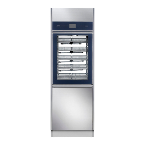
Smeg GW0260 User manual

User Manual
GW0260 - GW1260 - GW4260 - GW4290
193909119 rev.01
Page 1 –86
GW0260 - GW1260 - GW4260
GW4290
GW –LABORATORY GLASSWARE WASHERS
USER MANUAL
TRANSLATION OF THE ORIGINAL INSTRUCTIONS

User Manual
GW0260 - GW1260 - GW4260 - GW4290
193909119 rev.01
Page 2 –86
Table of Contents
1 INITIAL INSTRUCTIONS .............................................................................................................................. 6
2 INTENDED PURPOSE AND CLASSIFICATION............................................................................................... 7
2.1 INTENDED PURPOSE.......................................................................................................................... 7
2.2 LIFE CYCLE.......................................................................................................................................... 8
2.3 DEFINITION: “RESPONSIBLE BODY” IN RELATION TO THE DEVICE.................................................... 8
2.4 INTENDED USER AND SUPERUSER..................................................................................................... 8
3 PRESENTATION.......................................................................................................................................... 9
4 CONFIGURATIONS AND OPTIONAL ACCESSORIES..................................................................................... 9
4.1 Table of accessories......................................................................................................................... 10
4.2 GW0260........................................................................................................................................... 11
4.3 GW1260........................................................................................................................................... 12
4.4 GW4260........................................................................................................................................... 13
4.5 GW4290........................................................................................................................................... 14
4.6 REF –Configuration identifier ......................................................................................................... 15
5 SAFETY AND PRECAUTIONS FOR USE ...................................................................................................... 16
5.1 KEY TO THE SYMBOLS USED IN THE MANUAL AND ON THE DEVICE............................................... 16
5.2 GENERAL WARNINGS....................................................................................................................... 18
5.3 WARNINGS FOR HANDLING THE DEVICE......................................................................................... 20
5.4 ACCESSING AND REUSING THE DEVICE AFTER AN INCOMPLETE CYCLE AND ACCESSING THE
DEVICE AT END-OF-LIFE............................................................................................................................... 21
6 OPENING AND CLOSING OF THE DOOR................................................................................................... 22
6.1 MANUAL DOOR UNLOCKING / OPENING PROCEDURE................................................................... 23
6.2 OPENING THE HATCH OF THE SIDE CABINET –GW4290 ONLY....................................................... 24
7 COMMISSIONING .................................................................................................................................... 25
7.1 USING THE WATER SOFTENER......................................................................................................... 25
7.2 ADJUSTING THE SPRAY ARM WASHING PRESSURE......................................................................... 26
7.3 USINGDETERGENTS ......................................................................................................................... 27
7.3.1 LIQUID DETERGENT SUCTION SYSTEM –REPLACING AN EMPTY JERRY CAN.......................... 27
8 BASIC OPERATION ................................................................................................................................... 29
8.1 CONTROL AREA................................................................................................................................ 29
8.2 BUTTONS ......................................................................................................................................... 30
8.3 DISPLAY AND ICONS ........................................................................................................................ 31
8.4 With cycle preselected –information about program parameters ................................................ 33
8.4.1 Adjustments to current program............................................................................................. 34
8.5 SELECTING A PROGRAM .................................................................................................................. 34
8.6 STARTING THE PROGRAM ............................................................................................................... 34

User Manual
GW0260 - GW1260 - GW4260 - GW4290
193909119 rev.01
Page 3 –86
8.7 PROGRAM RUNNING....................................................................................................................... 35
8.7.1 PROGRAM RUNNING –“EASY MODE” DISPLAY ...................................................................... 35
8.8 PROGRAM COMPLETED................................................................................................................... 36
8.9 PROGRAM COMPLETED WITH ANOMALIES –WARNINGS.............................................................. 36
8.10 ALARMS –SERIOUS ANOMALIES..................................................................................................... 37
9 SETUP AND PARAMETER SETTING PROCEDURES.................................................................................... 38
9.1 Accessing the menus ....................................................................................................................... 40
9.2 Setup and dependent headings....................................................................................................... 40
9.3 SETTING THE TIME –Clock menu .................................................................................................... 44
9.4 SETTING THE DATE –Date menu..................................................................................................... 45
9.5 DRY HOUR COUNTER –DryH........................................................................................................... 45
9.6 CYCLE COUNTER –Count................................................................................................................. 46
9.7 PROGRAM ENABLING –PR EN......................................................................................................... 46
9.8 RESET ............................................................................................................................................... 46
9.8.1 RESET MC –Machine Configuration........................................................................................ 46
9.8.2 RESET ME –Machine Equipment ............................................................................................ 47
9.8.3 RESET DF –Dryer filter hours, relative decremental counter ................................................. 47
9.8.4 Reset RM –Number of cycles remaining before maintenance............................................... 48
9.9 PRINT –Reprint last cycle and machine parameters....................................................................... 48
9.10 LOG –Management of internal log, downloading of log file to USB drive ..................................... 49
9.11 ABOUT –firmware version installed ............................................................................................... 49
9.12 MEMORY AND PRINTOUT................................................................................................................ 50
9.13 EDITING CUSTOM PROGRAMS ........................................................................................................ 52
10 RECOMMENDED DETERGENTS AND IMPORTANT NOTICES................................................................ 53
11 PREPARING THE LOAD FOR THE WASHING AND DISINFECTION CYCLE .............................................. 55
12 ALARMS, WARNING AND DEVICE RESPONSE TO BLACKOUTS ............................................................ 56
12.1 WARNINGS....................................................................................................................................... 57
12.1.1 WARNING TABLE ..................................................................................................................... 58
12.2 ALARMS ........................................................................................................................................... 59
12.2.1 ALARM TABLE .......................................................................................................................... 60
13 CLEANING AND MAINTENANCE .......................................................................................................... 64
13.1 PRELIMINARY PRECAUTIONS........................................................................................................... 64
13.2 CLEANING THE DEVICE and its parts................................................................................................ 64
13.3 Cleaning the FILTERING UNIT .......................................................................................................... 66
13.4 IF THE DEVICE IS TO BE OUT OF USE ............................................................................................... 67
13.4.1 FOR A FEW HOURS .................................................................................................................. 67
13.4.2 FOR 24 HOURS OR MORE ........................................................................................................ 67
13.4.3 FOR 10 DAYS OR MORE ........................................................................................................... 67

User Manual
GW0260 - GW1260 - GW4260 - GW4290
193909119 rev.01
Page 4 –86
13.5 REUSING THE DEVICE AFTER A PERIOD OUT OF USE ...................................................................... 67
13.6 MAINTENANCE AND ROUTINE CHECK TIME INTERVALS................................................................. 68
13.6.1 DAILY........................................................................................................................................ 68
13.6.2 WEEKLY.................................................................................................................................... 68
13.6.3 EVERY SIX MONTHS ................................................................................................................. 68
13.6.4 EVERY YEAR.............................................................................................................................. 68
13.7 TROUBLESHOOTING ........................................................................................................................ 69
14 INSTALLATION...................................................................................................................................... 70
14.1 REMOVING THE PACKAGING AND PREPARING FOR HANDLING..................................................... 70
14.2 POSITIONING THE DEVICE ............................................................................................................... 70
14.3 INSTALLATION ON STAND ............................................................................................................... 71
14.4 ELECTRICAL CONNECTION REQUIREMENTS.................................................................................... 72
14.4.1 Power cable ............................................................................................................................. 72
14.5 WATER CONNECTION REQUIREMENTS........................................................................................... 73
14.5.1 WATER INTAKE ........................................................................................................................ 73
14.5.2 DEMINERALISED WATER REQUIREMENTS............................................................................... 74
14.5.3 UNPRESSURISED DEMINERALISED WATER –“PAD” ACCESSORY............................................ 74
14.6 WATER DRAIN REQUIREMENTS....................................................................................................... 75
14.7 TECHNICAL CHARACTERISTICS......................................................................................................... 76
14.7.1 WATER CONNECTIONS ............................................................................................................ 76
14.7.2 ELECTRICAL CONNECTIONS ..................................................................................................... 77
14.7.2.1 50 Hz version ....................................................................................................................... 77
14.7.2.2 60 Hz version ....................................................................................................................... 77
14.7.3 AMBIENT CONDITIONS............................................................................................................ 78
14.7.4 WEIGHT OF DEVICES AND STAINLESS STEEL MATERIALS........................................................ 78
14.7.5 CLASSIFICATION OF DEVICES, APPLIED DIRECTIVES AND STANDARDS................................... 78
14.8 DIMENSIONS OF PRODUCT AND CONNECTIONS ............................................................................ 79
14.8.1 GW0260 - GW1260 - GW4260................................................................................................. 79
14.8.2 GW4290................................................................................................................................... 80
14.9 CONNECTIONS AREA –ELECTRICITY AND WATER........................................................................... 81
14.9.1 CONNECTIONS TO 60 CM DEVICE –GW0260, GW1260, GW4260.......................................... 82
14.9.2 GW1260, GW4260 –Position of optional RS232 and LAN data ports..................................... 83
14.9.3 CONNECTIONS TO 90 CM DEVICE............................................................................................ 84
14.9.4 GW4290 –Position of optional LAN port ................................................................................ 85
15 AFTER-SALES SERVICE AND MANUFACTURER CONTACT DETAILS ...................................................... 86

User Manual
GW0260 - GW1260 - GW4260 - GW4290
193909119 rev.01
Page 5 –86
193909119
01
24/03/2023
Ins. GW0260
193909119
00
27/01/2023
First issue
Code
Rev.
Date
Notes

User Manual
GW0260 - GW1260 - GW4260 - GW4290
193909119 rev.01
Page 6 –86
1INITIAL INSTRUCTIONS
READ THIS USER MANUAL WITH CARE
This manual is an integral part of the device. Take good care of it and keep it to hand throughout the device’s life
cycle.
This manual and all the information it contains must be read carefully before using the device. Failure to read, any
misunderstanding or incorrect interpretation of the instructions provided in this manual may lead to misuse of the
device, put the operator at risk and impair the device’s performance.
Installation, maintenance and any repairs must be carried out by authorised technical staff.
Apart from leading to forfeiture of warranty cover, repairs performed by unauthorised staff
may put the user’s safety at risk.
Any components must always be replaced with genuine spare parts.
Use of the device in breach of the instructions provided by the manufacturer may jeopardise
the specified protection level (safety of the device) and the warranty cover for it (IEC 61010-1).
This device’s performance and safety have been tested with reference to the chemical products
recommended by the Manufacturer.
The Manufacturer declines all liability for uses other than those stated above.
Consumables (detergents, air filters, thermal printer paper, etc.) are not covered by the
warranty, except for any manufacturing defects.
The Warranty does not cover any parts found to be faulty due to negligent or careless use,
improper use, failure to comply with the device’s operating instructions, incorrect installation
or maintenance, maintenance or repairs performed using by unauthorised staff or repairs
made with non-genuine parts, damage during transport, or any circumstances in which the
device’s defects cannot be traced back to manufacturing faults. Any work relating to
installation and connection to the intake and drain systems, and the maintenance work
described in the user manual, are also excluded from the Warranty.
Any accessories may not be installed on the device by the user; this must be done by authorised
technical staff.
To request informative documentation to accompany accessories: contact the authorised dealer
and/or the authorised after-sales service, using the contacts provided in this manual (IEC 61010).
The information in this manual is provided for guidance only. The contents and the equipment described may be
subject to change without notice. Illustrations and the colours used in photographs, drawings and the forms which
reproduce the display are purely guideline, and intended to ensure that the user correctly understands the operating
concepts described in the text.

User Manual
GW0260 - GW1260 - GW4260 - GW4290
193909119 rev.01
Page 7 –86
2INTENDED PURPOSE AND CLASSIFICATION
2.1 INTENDED PURPOSE
PRODUCT DESCRIPTION: professional glassware washers, laboratory glassware washers (GW –glassware
washer).
Model
Key characteristics
GW0260
Laboratory glassware washers, 60 cm wide, without drying system, washing chamber in
stainless steel AISI304.
GW1260
Laboratory glassware washers, 60 cm, without drying system, washing chamber in stainless
steel AISI316.
GW4260
Laboratory glassware washers, 60 cm, with forced-air drying system, washing chamber in
stainless steel AISI316.
GW4290
Laboratory glassware washers, 90 cm, with forced-air drying system and side cabinet to take
detergent jerry cans, washing chamber in stainless steel AISI316.
INTENDED PURPOSE:
treatment, through washing and thermal disinfection, of glassware, laboratory components
and reusable components.
. The device was tested using the chemical products recommended in this manual. The use
of chemical products other than those recommended may impair the device’s fitness for its
intended purpose and its safety.
The device does not sterilise the load.
Sterilisation is performed by other devices (e.g. steam sterilisers) and is a treatment which
follows on from washing and thermal disinfection.
The washing trolley supports the load and determines type of load which can be processed
in a cycle. (The device is supplied as standard without washing trolleys; contact the
manufacturer for advice about the trolleys best suited to your needs.)
The instructions provided by the manufactures of the items in the load and the glassware
should always be followed when choosing the most appropriate treatment.
The operator’s own knowledge, especially of the Programs Table installed in the device
and the type of items for processing, is essential for selection of the correct treatment cycle:
the device offers various cycles with different time-temperature exposure (i.e. parameter A0)
values, which must be selected depending on the criticality of the load for processing.
It is essential to check the compatibility of the load for treatment with the specific washing
cycle chosen, in terms of the maximum temperatures reached and the chemicals used.
Information supplied in compliance with IEC 61010-2-040.
Any use other than that described in this manual constitutes misuse.
The manufacturer declines all liability for uses other than those stated above.
The manufacturer declines all liability for any damage caused by the use of the device to wash
instruments not approved by their manufacturers for automatic decontamination by means
of thermal disinfection.

User Manual
GW0260 - GW1260 - GW4260 - GW4290
193909119 rev.01
Page 8 –86
2.2 LIFE CYCLE
The “life cycle”, “lifetime” or “intended lifetime” is the period of time during which the device’s
characteristics and performance do not deteriorate to an extent which impairs the efficacy of the treatment
or the safety of the device.
Product life cycle: 10 years or 30000 cycles, whichever is reached first. This limit applies in normal conditions
of use with regular maintenance at the intervals and with the checks recommended in this manual,
performed by technical staff authorised by the manufacturer.
2.3 DEFINITION: “RESPONSIBLE BODY” IN RELATION TO THE DEVICE
Responsible body: “Individual or group responsible for the safe use and maintenance of equipment”.
Definition taken from the IEC 61010-1 standard.
(“RESPONSIBLE BODY: individual or group responsible for the safe use and maintenance of equipment”).
The responsible body should be clearly identified within the facility where the device is used, (for example
by recording the relative name and responsibilities on corporate forms).
2.4 INTENDED USER AND SUPERUSER
The device may only be used by specifically trained staff.
INTENDED USER PROFILE: the characteristics of the "TYPICAL USER" are as follows:
- staff specifically trained to use the device.
- staff trained concerning the washing thermal disinfection process and the correct cycle for treatment of
the load for processing.
Per device type “GW”: Technical staff working in a Laboratory.
The installation engineer is responsible for training the staff assigned to use the device at the time of
installation.
The manufacturer declines all liability in the event of malfunctions or accidents caused by use of the device
by untrained staff.
Staff training includes specific information on the possible risks involved in the use of the device, and
training in the safe performance of the operating procedures.
The installation engineer is also responsible for notifying the responsible body of the USER and SUPERUSER
passwords for access to the setup parameters. The responsible body must keep these passwords in a safe
place.
It is the duty of the device’s RESPONSIBLE BODY to ensure that those using the equipment have been
suitably trained in its operation, its safe use and routine checks, and that this training is suitably
maintained.
Staff training should be checked regularly.
The installation engineer is responsible for ensuring that the device operates correctly after commissioning.
Safety information supplied in compliance with IEC 61010-2-040.

User Manual
GW0260 - GW1260 - GW4260 - GW4290
193909119 rev.01
Page 9 –86
3PRESENTATION
The models referred to are small glassware washers with a single loading door.
The device’s user interface consists of an LCD screen and touch buttons for user interaction.
90 cm models have a side cabinet to accommodate the detergent jerry cans, and an electrical main switch.
They are also able to accommodate an optional printer to print the cycle report.
The door of the washing chamber may be in stainless steel or may have a clear glass section, depending on
the variant.
4CONFIGURATIONS AND OPTIONAL ACCESSORIES
The device’s default electrical connection is three-phase with neutral, indicated on the
technical dataplate as: 400 V 3N~ 50 Hz or 380 –400 V 3N~ 60 Hz, depending on the mains
frequency for which the device is preset.
The default version can be configured on site, by engineers authorised by the manufacture,
for the following power supply types:
-Three-phase without neutral.
-Single-phase.
Only authorised engineers may modify the product’s configuration, since they have access
to the operating procedures, the electrical system diagrams and the product testing
procedures.
Electrical connection variants available
Default connection 50 Hz, three-phase with neutral: 3N~ 400 V 50 Hz
Three-phase connection without neutral, 50 Hz: 230 V 3~ 50 Hz
Single-phase connection 50 Hz: 230 V ~ 50 Hz
Default connection 60 Hz, three-phase with neutral: 380 –400 V 3N~
Three-phase connection without neutral, 60 Hz: 220 –230 V 3~ 60 Hz
Single-phase connection 60 Hz: 220 –230 V ~ 60 Hz

User Manual
GW0260 - GW1260 - GW4260 - GW4290
193909119 rev.01
Page 10 –86
4.1 Table of accessories
The model may be equipped with a number of optional accessories; refer to the configuration table
provided below.
Key to symbols
Feature present
Optional feature (Some of these features can only be installed in the factory at the time of
ordering. Contact authorised sales staff for correct configuration of the product.)
-
Feature not present and not installable
IMPORTANT –DISPENSING OF CHEMICAL AGENTS
Chemical agents are dispensed by means of peristaltic pumps.
Where possible, each peristaltic pump installed should be combined with the control systems
available:
1. Chemical dosage control –by means of flow sensors;
2. Control of level in jerry can –by means of level sensors.
Unless the control systems are installed, the device is unable to check that the volume actually
dispensed is as preset and to alert the user when the product is about to run out.
The control devices can also be installed on site, by technical staff authorised by the manufacturer.
On 60cm models, GW1260 and GW4260: optional pumps P3 and P4 can only be installed as
alternatives to each other.
On GW4290 both optional pumps, P3 and P4, can be installed.
Contact your authorised dealer for information and explanations.

User Manual
GW0260 - GW1260 - GW4260 - GW4290
193909119 rev.01
Page 11 –86
4.2 GW0260
Model Name
GW0260
Type of door (bottom-hinged/sliding)
Bottom-
hinged
Number of doors (access to chamber:
single/double)
Single
Drying system
-
HEPA H14 absolute drying filter
-
Steam condenser
-
Built-in softener
Cold water connection
Hot water connection
-
Demineralised water connection
DD –Powder detergent dispenser in inner door
P1 –Peristaltic detergent pump
P2 –Peristaltic neutralising agent pump
[Peristaltic pumps P3 and P4 are optional]
-
P1 detergent dispensing monitoring
-
P2 acid neutralising agent dispensing monitoring
-
P3 detergent dispensing monitoring
-
P4 detergent dispensing monitoring
-
P1 –SL1 can level monitoring
-
P2 –SL2 can level monitoring
-
P3 –SL3 can level monitoring
-
P4 –SL4 jerry can level monitoring
-
Aquastop
Built-in panel printer
-
RS232 port (printer connection)
-
USB port
LAN communication port
-
Demineralised water pump (booster pump)
Integral drain pump for wall drain
Conductivity probe
-
Double drain valve
-
Non-customisable factory-set programs
N.7
+ 2 Service
Custom programs
-
Side cabinet to accommodate detergent jerry
cans
-
Electrical main switch
-

User Manual
GW0260 - GW1260 - GW4260 - GW4290
193909119 rev.01
Page 12 –86
4.3 GW1260
Model Name
GW1260
Type of door (bottom-hinged/sliding)
Bottom-
hinged
Number of doors (access to chamber:
single/double)
Single
Drying system
-
HEPA H14 absolute drying filter
-
Steam condenser
Built-in softener
Cold water connection
Hot water connection
Demineralised water connection
DD –Powder detergent dispenser in inner door
P1 –Peristaltic detergent pump
P2 –Peristaltic neutralising agent pump
[Peristaltic pumps P3 and P4 are optional]
P1 detergent dispensing monitoring
P2 acid neutralising agent dispensing monitoring
P3 detergent dispensing monitoring
P4 detergent dispensing monitoring
P1 –SL1 can level monitoring
P2 –SL2 can level monitoring
P3 –SL3 can level monitoring
P4 –SL4 jerry can level monitoring
Aquastop
Built-in panel printer
-
RS232 port (printer connection)
USB port
LAN communication port
Demineralised water pump (booster pump)
Integral drain pump for wall drain
Conductivity probe
-
Double drain valve
-
Non-customisable factory-set programs
20
Custom programs
20
Side cabinet to accommodate detergent jerry
cans
-
Electrical main switch
-

User Manual
GW0260 - GW1260 - GW4260 - GW4290
193909119 rev.01
Page 13 –86
4.4 GW4260
Model Name
GW4260
Type of door (bottom-hinged/sliding)
Bottom-
hinged
Number of doors (access to chamber:
single/double)
Single
Drying system
Relative drying filter
HEPA H14 absolute drying filter
Steam condenser
Built-in softener
Cold water connection
Hot water connection
Demineralised water connection
DD –Powder detergent dispenser in inner door
P1 –Peristaltic detergent pump
P2 –Peristaltic neutralising agent pump
[Peristaltic pumps P3 and P4 are optional]
P1 detergent dispensing monitoring
P2 acid neutralising agent dispensing monitoring
P3 detergent dispensing monitoring
P4 detergent dispensing monitoring
P1 –SL1 can level monitoring
P2 –SL2 can level monitoring
P3 –SL3 can level monitoring
P4 –SL4 jerry can level monitoring
Aquastop
Built-in panel printer
-
RS232 port (printer connection)
USB port
LAN communication port
Demineralised water pump (booster pump)
Integral drain pump for wall drain
Conductivity probe
-
Double drain valve
-
Non-customisable factory-set programs
20
Custom programs
20
Side cabinet to accommodate detergent jerry
cans
-
Electrical main switch
-

User Manual
GW0260 - GW1260 - GW4260 - GW4290
193909119 rev.01
Page 14 –86
4.5 GW4290
Model Name
GW4290
Type of door (bottom-hinged/sliding)
Bottom-
hinged
Number of doors (access to chamber:
single/double)
Single
Drying system
Relative drying filter
HEPA H14 absolute drying filter
Steam condenser
Built-in softener
Cold water connection
Hot water connection
Demineralised water connection
DD –Powder detergent dispenser in inner door
P1 –Peristaltic detergent pump
P2 –Peristaltic neutralising agent pump
[Peristaltic pumps P3 and P4 are optional]
P1 detergent dispensing monitoring
P2 acid neutralising agent dispensing monitoring
P3 chemical agent dispensing monitoring
P4 chemical agent dispensing monitoring
-
P1 –SL1 can level monitoring
P2 –SL2 can level monitoring
P3 –SL3 can level monitoring
P4 –SL4 jerry can level monitoring
Aquastop
Built-in panel printer
RS232 port (printer connection)
-
USB port
LAN communication port
Demineralised water pump (booster pump)
Integral drain pump for wall drain
Conductivity probe
-
Double drain valve
-
Non-customisable factory-set programs
20
Custom programs
20
Side cabinet to accommodate detergent jerry
cans
Electrical main switch

User Manual
GW0260 - GW1260 - GW4260 - GW4290
193909119 rev.01
Page 15 –86
4.6 REF –Configuration identifier
REF: the REF of a product, which appears on its technical dataplate, is its “catalogue number”, the code
which enables unique identification of its configuration.
E.g. GW1260-SC-000 identifies model GW1260:
1. Equipped with peristaltic pumps P1 and P2
2. With steam condenser
3. Electrical connection three-phase with neutral 3N~ 50 Hz
4. Chamber and inner door STD, AISI 316
The REF code is built up by combining the following fields.
Type
SERIES
1st
character
2nd
character
3rd
character
4th
character
5th
character
6th
character
7th
character
GW
0260
-
S
C
-
0
0
0
1260
P
0
6
G
4260
0
J
4290
Legend
1st character: separator
-
Fixed field
2nd character: detergent dispensing configuration
S
Peristaltic pumps P1 and P2 installed
P
Peristaltic pumps and special equipment for Petrol sector installed
0
Powder detergent dispenser in inner door and peristaltic pump P2 installed
3rd character: whether or not steam condenser is installed
C
Steam condenser present
0
No steam condenser
4th character: separator
-
Fixed field
5th character: electrical connection
0
Three-Phase with Neutral (configurable)
6th character: mains frequency
0
50 Hz
6
60 Hz
7th character: Chamber and inner door materials
0
Chamber and inner door STD, AISI 316
J
Chamber and inner door AISI 304
G
Chamber in AISI 316, inner door in AISI 316 and Glass (G: Glass)

User Manual
GW0260 - GW1260 - GW4260 - GW4290
193909119 rev.01
Page 16 –86
5SAFETY AND PRECAUTIONS FOR USE
5.1 KEY TO THE SYMBOLS USED IN THE MANUAL AND ON THE DEVICE
The following is the key to the symbols used on the device and in this manual, as required by IEC 61010-2-
040.
SYMBOL
MEANING
Read this information carefully.
Symbol which appears beside particularly important instructions or warnings.
Power “ON”
Standard symbol (IEC 60417:1 –5007): appears on the electrical main switch, if provided on devices,
to indicate connection to the mains power supply.
Power “OFF”
Standard symbol (IEC 60417:1 –5008): appears on the electrical main switch (circuit breaker) to
indicate disconnection from the mains power supply.
Manufacturer
The symbol appears on the product’s technical dataplate, accompanied by the name and address of
the medical device's Manufacturer.
(ISO 15223-1 –Symbol 5.1.1, ISO 7000 no. 3082)
Country of manufacture
The symbol indicates products’ country of manufacture (IT). If it is accompanied by a date, this is the
date of reference for manufacture.
(ISO 15223-1 –Symbol 5.1.11, “Country of manufacture”)
Consult instructions for use.
The symbol appears on the product’s technical dataplate to indicate that users must consult the
instructions for use of the device.
(ISO 15223-1 –Symbol 5.4.3, ISO 7000 no. 1641)
Warning, danger.
The symbol appears in the manual next to safety instructions.
Warning, hot surface.
The symbol is affixed to the device close to parts which may heat to high temperatures and constitute
a burn hazard –do not touch parts near this symbol. The symbol appears in the manual to emphasise
safety instructions relating to the burn hazard.
Warning, electric shock hazard.
The symbol is affixed close to live parts –the device’s power supply must be disconnected before
doing any work on these parts. Do not touch live parts if the power supply has not been
disconnected.
Laboratory Sector.
USB port –Data communication and programming of the device.
Transport, storage and unpacking precautions.
Biological hazard.

User Manual
GW0260 - GW1260 - GW4260 - GW4290
193909119 rev.01
Page 17 –86
SYMBOL
MEANING
Flammability hazard.
“Crossed dustbin” symbol. This device is tagged under European Directive 2012/19/EU ON WASTE
ELECTRICAL AND ELECTRONIC EQUIPMENT (WEEE) (ref. annex IX of directive). The symbol appears on
the product’s technical dataplate and the pack label: at the end of its working life, the product must
be consigned to a disposal plant for recovery and recycling in accordance with the relevant legislation
in the country of installation. Contact the specialist disposal consortia.
The management of WEEE (waste electrical and electronic equipment) is the responsibility of
manufacturers, who must plan and operate collection systems; used equipment can now be
consigned directly to the dealer free of charge when purchasing new equipment of the same type.
All disposal expenses will be borne by the manufacturer only when purchasing an equivalent new
device to replace the previous one.
At end-of-life the device may be contaminated, especially the chamber and water circuit (e.g. if the
device has ended its working life due to a fault that has caused the failure of the last thermal
disinfection cycle): take appropriate care when decommissioning.
Make sure that it is scrapped correctly to safeguard the environment and health.
Once decommissioned, the device must be rendered unusable. Cut the power supply cable after
removing the plug / disconnecting the cable from the power socket.
Before the old device can be disposed of, all accessible, old batteries and storage batteries must be
separated from the old device. The same applies to lamps, which can be removed from the old device
without damaging them. The end user is also responsible from obliterating any personal data on the
old device.
Notes on the recycling of materials
Help to recycle all materials marked with this symbol. Do not dispose of these materials, especially
packaging, with household waste; use the special recycling bins or the local collection systems
provided.
CE marking; the manufacturer guarantees compliance with the EU directives applicable to the
product.
Type of product “GW” – Laboratory glassware washers.
#
The # symbol identifies the Model (e.g. “GW4260”)
REF
The REF of a product, which appears on its technical dataplate, is its “catalogue number”, the code
which enables unique identification of its configuration (e.g. “GW4260-SC-000”).

User Manual
GW0260 - GW1260 - GW4260 - GW4290
193909119 rev.01
Page 18 –86
5.2 GENERAL WARNINGS
MAXIMUM LOAD WEIGHT
Leaning or sitting on the open door of the device might cause it to tip over, putting people in
danger. The door is not designed primarily to support loads.
Safety information: the maximum weight which can be loaded on the door, including the
weight of the instrument rack, must never exceed: 37 kg. If the weight of the instrument trolley
and baskets is excluded, the maximum load must never exceed: 23 kg.
N.B.: the maximum load which can actually be processed depends on the correct arrangement
of the items, as instructed in the “Preparing the Load” section. In particular, items in the load
must never be overlapped.
MALFUNCTIONS and PERFORMANCE ANOMALIES
In case of operating anomalies or unforeseen events: read the “ALARMS” section of this
manual and, if appropriate, contact your nearest Authorised Service Centre.
In the event of water leaks: disconnect the device from the electricity supply and turn off the
water taps.
If the device’s interface display remains off or unresponsive even with the main switch
correctly set ON: do not touch the display as this may trigger unexpected operation of parts
of the device. Switch the device off using the main switch. Wait at least 10 seconds after
switching off before switching back on again.
Refer to the “TROUBLESHOOTING" section.
If changes in the device’s performance are noticed check:
1. That all operating conditions are as specified by the manufacturer in this manual and the
documentation supplied with the product.
2. That all maintenance procedures and recommended intervals have been complied with,
If the device’s performance is non-compliant, contact the authorised after-sales service to have
it checked and repaired.
The USB port on the product cannot be used for USB charging.
The port must only be used with the USB sticks supplied by the manufacturer and according to
the methods indicated in the user manual.
Maintenance: change drying filter (if installed)
The device provides an alert when the filter needs changing. Keeping the filter in operation after
the end of its useful life will lead to poor drying results. If the filter is fouled, the drying air flow
rate is reduced.
The filter’s useful life may be less than the preset nominal time, depending on the amount of dirt
in the environment. If drying performance deteriorates, users should have the filter changed
earlier. The device does not signal this type of wear, but only wear arising from the hours actually
worked.

User Manual
GW0260 - GW1260 - GW4260 - GW4290
193909119 rev.01
Page 19 –86
Routine maintenance
The device provides an alert when routine maintenance is required.
These are inspection and maintenance operations which must be performed by authorised staff
to keep the device safe and in good working order.
These maintenance operations are not covered by the product Warranty, which does not include
the replacement of components which deteriorate due to normal wear and tear.
USE OF AND ACCESS TO THE DEVICE
The device must only be used by staff suitably trained in its operation.
The chamber of the device is not designed for users to climb into it. The user must never climb
into the chamber –this might put their safety at risk (ref. IEC 61010-2-040:2015 –7.102).
REPORTING SERIOUS INCIDENTS
The person responsible for the device is obliged to report any serious incident occurring in
relation to it to the manufacturer.
The authorised after-sales service will interface with the headquarters after-sales service for
timely management of the event.
RECOMMENDED DETERGENTS AND CHEMICALS
The device’s performance, reliability and safety have been tested with reference to the
chemical products recommended by the Manufacturer.
As well as performance tests, specific tests relating to safety aspects regarding the emission of
substances into the workplace where the device is installed have also been conducted.
Use of the device in combination with chemicals other than those recommended by the
manufacturer may cause a deterioration of its performance and lead to problems regarding the
safety of the device, its operators and the environment, for which the Manufacturer cannot be
held responsible.
DEMINERALISED WATER
A connection to a demineralised water supply is necessary for installation of the device.
If demineralised water is not available, the user is responsible for ensuring that the quality of
the water supplied to the device does not cause mineral salts or other substances to be
deposited on the instruments processed, rendering their subsequent use unsafe.
FLAMMABLE SUBSTANCES
Do not place flammable substances inside the device. Do not use flammable detergents.
Do not place alcohol or solvents such as turpentine, which might cause an explosion, inside the
device. Do not place materials dirty with ash, wax or paint inside the device.

User Manual
GW0260 - GW1260 - GW4260 - GW4290
193909119 rev.01
Page 20 –86
5.3 WARNINGS FOR HANDLING THE DEVICE
The device is shipped packaged: standing on and affixed to a wooden pallet and
enclosed in cardboard packaging material. Do not use devices which have been
damaged in transit.
STORAGE: the device must be stored in an enclosed place (not outside) and must be placed
in an environment having the same temperature and humidity values as those specified for
operation.
Moving the device to the intended place of operation is the responsibility of the customer
and requires the use of a forklift truck.
Consult the product technical datasheet for information on the device weight, net and gross
including the pack.
Unpacking operations:
1. Remove the outer straps from the pack.
2. Open and remove the cardboard box and nylon wrapping.
3. Do not rest the device on its sides.
4. Remove the polystyrene corner protections.
5. The base of the device is secured to a pallet for lifting and transporting it. The self-
tapping wood screws used to secure the device to the pallet must be removed in
order to place it in its installation position.
6. Place the device on a horizontal surface with a slope of no more than 2°; level using
the adjustable feet.
7. Do not place the device on a flammable surface.
8. Do not attempt to move the system by means of the door handles.
As far as possible, the product should not be moved around by hand.
If manual handling is unavoidable, at least 3 or more people must be used.
This manual suits for next models
3
Table of contents
Other Smeg Laboratory Equipment manuals
Popular Laboratory Equipment manuals by other brands

Dado Lab
Dado Lab QB1 user manual

Sartorius
Sartorius Centrisart G-16 operating manual

LAN Power
LAN Power LP-2590 installation guide

Okolab
Okolab UNO-T-H-PREMIXED Quick installation user's guide

Terra Universal
Terra Universal Ductless Exhaust Fume Hood Installation and operating guide

CenturionPro
CenturionPro GC1 owner's manual