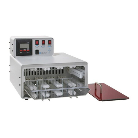
Egger EL 1 plus N2 User manual

egger Otoplastik+Labortechnik GmbH
Aybühlweg 59
87439 Kempten/Germany
egger EL 1 plus N2
Bedienungsanleitung
Operating instruction
REF 51110 (230 V)
Deutsche Anleitung: Seite 1-12
English version see: page 13-24

2
egger EL 1 plus N2
Bitte lesen Sie die Betriebsanleitung aufmerksam, bevor
Sie mit dem Gerät arbeiten!
Bewahren Sie die Betriebsanleitung zum späteren Ge-
brauch an einem sicheren Ort auf!
Inhaltsverzeichnis Seite
1 Allgemeines 3
2 Sicherheitshinweise 3
2.1 Sicherheitsbewusst arbeiten 4
3 Installation, Bedienung und Inbetriebnahme 4
3.1 Lieferumfang 4
3.2 Leistungsmerkmale 4
3.3 Ersatzteile/Zubehör 5
3.4 Gerät aufstellen und anschließen 5
3.5 Bedienung 6
3.6 Timer programmieren 6
4 Arbeiten mit den Lichtpolymerisaten 7
4.1 Lagerung 7
4.2 Besondere Verarbeitungshinweise 7
4.3 Ohne Gas polymerisieren 7
4.4 Mit Gas nachpolymerisieren 8
4.5 Lackierung mit LP/H Lacken 8
4.6 Lackierung mit LP/W Lack 8
4.7 Reparaturen/Modifikationen mit Modellierpasten 9
5 Wartung 9
5.1 Auswechseln der Lichtröhren 9
5.2 Lebensdauer der Lichtröhren 9
5.3 Anordnung der Lichtröhren 10
5.4 Austausch der Reflektorfolie 10
6 Garantie/Service/Kundendienst 10
!
Legende
Wichtige Information
Warnung
!

3
egger EL 1 plus N2
1. Allgemeines
Das Lichtpolymerisationsgerät egger EL 1 plus N2ist eine
Weiterentwicklung des Gerätes egger EL 1.
Anstelle von Glyzerin verwendet das egger EL 1 plus
N2Gas* zur Endhärtung der Otoplastiken, Schalen und
Ventings. Das Gas ist zu- und abschaltbar, so dass die
dritte Polymerisation unter Zugabe von Gas durchgeführt
wird und nicht wie bisher in einem Cleaner-Bad.
Das egger EL 1 plus N2kann für verschiedene Verfah-
renstechniken eingesetzt werden.
Mit dem Gerät lassen sich lichthärtende Werkstoffe un-
terschiedlicher Konsistenz und Pigmentierung bearbeiten.
Das Gerät ist mit einem hochwertigen Timer ausgestattet,
der sich auf alle Anforderungen hochentwickelter Verfah-
renstechniken sekundengenau einstellen lässt.
Das Gerät ist mit UVA- und Blaulichtröhren bestückt.
Die Röhren sind in bestimmten Ebenen angeordnet. Dies
gewährleistet sowohl eine bessere Oberflächen-, als auch
eine bessere Tiefenpolymerisation. Die Röhrenebenen
sind einzeln zu- und abschaltbar, je nach angewandter
Verfahrenstechnik.
Der steuerbare Lüfter im Gerät verhindert eine Überhit-
zung der Lichtkammer.
Mit dem Gerät können bei der Verwendung von Nega-
tivformen mit einem Durchmesser von 5 cm bis zu 12
IdO- oder 8 HdO-Otoplastiken gleichzeitig polymerisiert
werden.
Das Gerät ist einfach zu bedienen und wartungsfreund-
lich.
Das formschöne, stabile Metallgehäuse ist pulverbe-
schichtet und leicht zu pflegen.
Das Auswechseln der Röhren ist einfach und zeitsparend.
Weitere Ersatzteile lassen sich ebenso leicht austau-
schen.
Das Lichtpolymerisationsgerät egger EL 1 plus N2wurde
für die unten beschriebenen Anwen-dungen speziell ent-
wickelt und zeichnet sich aus durch
• wartungsfreies Arbeiten
• schnelles Auswechseln der UVA- und Blaulichtröhren
• einfache Bedienbarkeit
• leichte Reinigung und Pflege des pulverbeschichteten
Metallgehäuses
Außerdem können wir eine Vielzahl von Geräten und
nützlichem Zubehör aus unserem umfangreichen Sorti-
ment anbieten. Fordern Sie unseren Katalog an oder be-
suchen Sie uns unter www.egger-labor.com.
* Als Gas wird Nitrogen 2.6 (Stickstoff) verwendet. 2.6 ist
der Reinheitsgrad in Prozent vom Gas-volumen. Die erste
Ziffer („2“) gibt die Anzahl der Neuner vor dem Komma
an, die zweite Ziffer („6“) gibt die erste Zahl nach dem
Komma an. Die Reinheit von Nitrogen 2.6 ist somit 99,6 %.
2 Sicherheitshinweise
Das elektrische Lichtpolymerisationsgerät egger EL
1 plus N2 wird zum Polymerisieren von lichthärtenden
LP Materialien, Modellierpasten und Lacken eingesetzt.
Ein anderer Einsatz, als der in dieser Betriebsanleitung
beschrieben, kann zu Personenschäden führen. Ferner
können das Gerät oder andere Sachwerte beschädigt
werden. Deshalb dürfen Sie das Gerät nur in technisch
einwandfreiem Zustand benutzen und Sie müssen diese
Sicherheitshinweise unbedingt beachten.
!

4
egger EL 1 plus N2
2.1 Sicherheitsbewusst arbeiten
• Gerät nur an einem trockenen, vor Staub geschützten
Arbeitsplatz betreiben.
• Das Gerät darf nur von sachkundigen Personen
benutzt werden, die entsprechend qualifiziert und
ausgebildet sind.
• Vor der Inbetriebnahme muss der Benutzer die Be-
triebsanleitung lesen und bei eventuellen Unklarheiten
beim Hersteller rückfragen.
• Gerät nur in einwandfreiem, sauberem Zustand und
mit voll funktionsfähigen UVA- und Blaulichtröhren
betreiben.
• Vor dem Einschalten des Gerätes muss immer der
Lichtschutzdeckel aufgesetzt werden.
• Die Nitrogengasflasche muss immer mit Druckmin-
derer betrieben werden.
• Lüftungsschlitze am Gerät nicht abdecken. Keine
Gegenstände durch die Lüftungsschlitze stecken.
• Das Gerät nur an zugelassene Steckdosen anschließen.
• Anerkannte Regeln für Arbeitssicherheit beachten.
• Mit diesem Gerät werden lichthärtende Materialien
im Spektralbereich von 350-520 nm verarbeitet.
Bitte beachten Sie auch die Verarbeitungsanleitung
und Produktinformation für das Material.
• Netzstecker nicht am Netzkabel aus der Steckdose
ziehen.
• Ist das Netzkabel beschädigt, muss es sofort ausge-
tauscht werden. Mit defekten Stromzuführungen darf
nicht weitergearbeitet werden.
• Reparaturen am Gerät dürfen nur vom Hersteller
durchgeführt werden.
• Servicearbeiten (Reinigung, Austausch der UVA- und
Blaulichtröhren oder der Reflektorfolie) nur bei ausge-
schaltetem Gerät durchführen. Netzstecker aus der
Steckdose ziehen!
• Bei Austausch nur die Original-Lichtröhren und
Reflektoren von egger verwenden.
• Zur Reinigung des Gerätes keine Lösungsmittel
verwenden. Gerät nicht in Flüssigkeit tauchen.
• Kinder sind vom Gerät fernzuhalten.
Bei selbst durchgeführten Reparaturen oder der
Verwendung anderer Ersatzteile erlöschen sämtliche Ga-
rantie- und Haftungsansprüche!
3 Installation, Bedienung und Inbetrieb-
nahme
3.1 Lieferumfang
Prüfen Sie alle Teile der Lieferung auf Vollständigkeit und
Transportschäden. Fehlende Teile oder Transportschäden
bitte sofort uns bzw. Ihrem Händler melden.
Das Lichtpolymerisationsgerät egger EL 1 plus N2enthält:
1 Gerät mit Lichtschutzdeckel
1 Netzkabel
1 Metallplatte als Lackiereinsatz
1 Plastikbox mit abnehmbarem Deckel
1 Gasanschlussschlauch: Länge 1,5 m;
Durchmesser 6 x 8 mm
1 Betriebs- und Verarbeitungsanleitung
und kann somit sofort in Betrieb genommen werden.
3.2 Leistungsmerkmale des Lichtpolymerisationsge-
räts egger EL 1 plus N2
Netzspannung: 230 V +/- 10 %
Netzfrequenz: AC 50 Hz
Anschlussart: Netzstecker Schuko deutsch
Leistungsaufnahme: AC 250 A
Gas: Nitrogen 2.6 (Stickstoff)
!
!

5
egger EL 1 plus N2
3.3 Ersatzteile und Zubehör für Lichtpolymerisations-
gerät egger EL 1 plus N2
UVA- Lichtröhre REF 50103
Blaulichtröhre REF 50104
Plastikbox mit Deckel REF 51114
Lichtschutzdeckel REF 51102
Reflektorfoliensatz REF 51104
Kunststoffplatte transparent REF 51103
Timer REF 51109
3.4 Gerät aufstellen und anschließen
Das Lichtpolymerisationsgerät egger EL 1 plus N2ent-
spricht dem aktuellen Stand der Technik und den an-
erkannten sicherheitstechnischen Regeln. Trotzdem
können Gefahren auftreten. Beachten Sie daher vor der
Inbetriebnahme folgende Punkte:
• Gerät darf nur von qualifiziertem Fachpersonal
betrieben werden.
• Anerkannte Regeln für Arbeitssicherheit beachten.
• Gerät nur in einwandfreiem Zustand und unter
Beachtung der Betriebsanleitung betreiben.
• Stellen Sie das Gerät waagerecht auf und bringen Sie
es in die geeignete Arbeitsposition.
• Ziehen Sie die Schutzfolien von Arbeitstisch und
Lichtschutzdeckel ab.
• Schützen Sie das Gerät vor Erschütterungen.
• Prüfen Sie, ob das Gerät trocken ist.
• Prüfen Sie das Gerät auf technisch einwandfreien
Zustand, ganz besonders das Netz-kabel!
• Stecken Sie das Netzkabel ein.
Achtung:
• Nitrogengasflaschen müssen ausreichend gesichert
werden (Kette etc.)
• Schrauben Sie den Druckminderer auf die Gasflasche.
• Verbinden Sie das Ende des Druckschlauches mit
dem Druckminderer der Gasflasche.
• Stecken Sie den Druckschlauch in die Schnellkupplung
an der Geräterückseite (bis Anschlag). Zum Lösen der
Verbindung, den Sicherungsring an der Schnellkupplung
nach innen drücken und Schlauch wieder heraus-
ziehen.
• Stecken Sie das Netzkabel ein.
• Bevor Sie das Flaschenventil öffnen, muss das
Ausgangsventil am Flaschendruckminderer und
Regelventil am Durchflussregler geschlossen werden.
• Öffnen Sie das Flaschenventil und stellen Sie den
Druck mit der Einstellschraube am Druckminderer
auf ca. 1-1,5 bar ein. Das linke Manometer zeigt den
Druck der Flasche an, das rechte Manometer den
Ausgangsdruck.
• Öffnen Sie das Ausgangsventil ganz, N2-Schalter
muss auf Position „EIN“ stehen.
• Am Timer können Sie eine beliebige Zeit einstellen
und das Gerät starten.
• Öffnen Sie langsam das Regelventil des Durchfluss-
gebers bis die Unterkante des Schwebekörpers
2 Liter pro Minute anzeigt. Sollte die Anzeige im
rechten Manometer stark abfallen, sollten Sie am
Flaschendruckminderer nachregeln.
• Mit der Taste „Stop“ beenden Sie nun den Vorgang.
Das Gerät ist einsatzbereit.
• Zum Abstellen der Gasanlage schließen Sie das
Flaschenventil. Der Restdruck muss nicht abgelassen
werden.
• Zum Gasflaschenwechsel muss der Restdruck
abgelassen werden.

6
egger EL 1 plus N2
3.5 Bedienung des Lichtpolymerisationsgerätes
egger EL 1 plus N2
Hauptschalter
• Ort: Rückseite des Gerätes.
• Funktion: Der Schalter ist normalerweise immer
eingeschaltet. Bei längeren Betriebs-pausen sollten
Sie das Gerät ausschalten.
Schnellkupplung
• Ort: Rückseite des Gerätes
• Funktion: Aufnahme des Gasanschlussschlauches
Drei Schalter für die Lichtebenen
• Ort: Frontplatte des Gerätes.
• Funktion: Die Schalterstellungen sind durch Symbole
gekennzeichnet. Je nach Schalterstellung (Symbol)
wird die dazugehörige Lichtebene beim Starten des
Timers eingeschaltet. Die zugehörige Kontrollleuchte
geht an.
Drei Kontrollleuchten für die Lichtebenen
• Ort: Frontplatte des Gerätes (in den Schaltern für die
Lichtebenen).
• Funktion: Anzeige der Lichtebenen.
Ventilatorschalter
• Ort: Frontplatte des Gerätes.
• Funktion: Der Ventilator wird automatisch durch den
Timer aktiviert. Dies reicht für einen normalen Betrieb
des Gerätes aus. Bei Dauerbetrieb des Gerätes stellen
Sie den Ventilatorschalter auf Stellung „VENT“. Jetzt
läuft der Ventilator ununterbrochen.
Einschalter für Gas
• Ort: Frontplatte des Gerätes.
• Funktion: Aktivierung des Gases. In Stellung „EIN“
findet die Polymerisation unter Nitro-gengas statt. Die
zugehörige Kontrollleuchte geht an. Der Gasfluss wird
automatisch durch den Timer gesteuert.
Kontrollleuchte für Gas
• Ort: Frontplatte des Gerätes (im Einschalter für Gas).
• Funktion: Zeigt die Aktivierung des Gases an.
Gasdurchflussregler
• Ort: Frontplatte des Gerätes.
• Funktion: Regelt den Gasdurchfluss. Wenn das Gerät
mit Gas betrieben wird, muss die im Inneren befind-
liche Metallkugel auf die Stellung „50 mm“ justiert
werden. Dies kann nur im Betrieb durchgeführt
werden, da der Gasfluss lichtabhängig ist.
Akustisches Signal
• Ort: Im Timer
• Funktion: Signalisiert das Ende des Arbeitsganges.
3.6 Timer programmieren
Arbeitszyklus einstellen
Schalten Sie das Gerät ein (Hauptschalter).
Die Taste (PROG) 1 x für Stunden, 2 x für Minuten und
3 x für Sekunden kurz betätigen, bestätigt wird durch
einen Signalton. Die entsprechende Stelle im Display
des Timers blinkt. Mit der Taste (+/-) den gewünschten
Wert einstellen. Im Minuten- und Sekunden-Modus kann
durch längeres Betätigen der (+/-) Taste in 10er Schrit-
ten der Wert verändert werden. Bestätigung mit der Taste
(PROG), dann erscheint die eingestellte Zeit im Display.

7
egger EL 1 plus N2
Starten und Stoppen des Timers
Starten und Stoppen des Timers mit der Taste (START/
STOPP).
Bei Erreichen von 0:00:00 ertönen 2 Signaltöne und im
Display blinkt das Glockensymbol. Der Timer springt nach
Ablauf automatisch auf die zuletzt eingestellte Zeit.
Rücksetzen des Timers auf 0:00:00
Alle 3 Tasten kurz gleichzeitig betätigen.
Rücksetzen auf die Startzeit des Timers
Nach dem eventuellen Stoppen der Ablaufzeit mit der
Taste (START/STOPP) kann der Timer mit der Taste (RESET)
auf die letzte eingestellte Zeit zurückgestellt werden.
Systemreset
Alle 3 Tasten des Timers gleichzeitig für etwa 4 Sekunden
drücken.
4. Arbeiten mit den Lichtpolymerisaten
4.1 Besondere Lagerhinweise
Die Materialien sollten kühl (bei max. Zimmertemperatur
von ca. 23 °C) und trocken gelagert werden. Achten Sie
darauf, die Behälter immer geschlossen zu halten und
nach Gebrauch sofort wieder zu verschließen. Ansonsten
besteht die Gefahr, dass durch Lichteinwirkung eine un-
gewollte chemische Reaktion (Aushärten des Materials)
ausgelöst wird. Die Haltbarkeit bei korrekter Lagerhal-
tung ist auf dem Produkt angegeben.
TIPP: Angebrochene Packungen von Lacken empfeh-
len wir im Kühlschrank aufzubewahren.
4.2 Besondere Verarbeitungshinweise
Der direkte Hautkontakt mit den Materialien ist zu ver-
meiden. Vor der Benutzung sollten die Hände durch ent-
sprechende Hautschutzpräparate oder durch das Tragen
von Handschuhen geschützt werden.
Die Materialien dürfen nur von ausgebildetem Fachper-
sonal verarbeitet werden. Die Verarbeitung der Lacke
sollte unter einem Abzug erfolgen (z. B. egger S/AB Timer
REF 61400). Die Lackierpinsel immer nur für eine Lackart
verwenden. Bitte beachten Sie die Verarbeitungshinweise
für die Materialien.
Die Hinweise zur Entsorgung sind dem Sicherheitsdaten-
blatt für das jeweilige Produkt zu entnehmen.
Die Sicherheitsdatenblätter können Sie jederzeit unter
www.egger-labor.com als PDF-Datei herunterladen.
Für die Verarbeitung empfehlen wir als nützliches Zube-
hör das egger-Lackierhalterset mit der REF 51207, be-
stehend aus magnetischen Lackierhaltern (REF 51206),
Erkogum (REF 30911) und Nylonrohr (REF 97200).
4.3 Ohne Gas polymerisieren
• Die Plastikbox ist aus dem Gerät entfernt.
• Der Netzstecker ist eingesteckt.
• Der Einschalter für das Gas darf nicht auf „EIN“ stehen.
• Schalten Sie das Gerät ein (Hauptschalter).
• Stellen Sie das Polymerisationsgut in das Gerät.
• Verschließen Sie das Gerät mit dem Sichtschutzdeckel.
• Stellen Sie am Timer die gewünschte Polymerisations-
zeit ein.
• Drücken Sie die Taste „START/STOPP“.
• Der Timer wird gestartet.
• Wenn die Polymerisation beendet ist, ertönt ein
Signal. Das Gerät schaltet automatisch ab.

8
egger EL 1 plus N2
4.4 Mit Gas nachpolymerisieren
Voraussetzungen:
• Die Plastikbox steht auf dem Arbeitstisch des Gerätes.
• Gerät und Nitrogenflasche sind durch den Gasan-
schlussschlauch miteinander verbunden.
• Der Netzstecker ist eingesteckt
• Schalten Sie das Gerät ein (Hauptschalter).
• Legen Sie das Polymerisationsgut in die Plastikbox.
• Das Polymerisationsgut darf sich nicht berühren!
• Legen Sie Schalen und Ventings mit der Öffnung
nach oben in die Plastikbox.
• Verschließen die Plastikbox mit dem Deckel.
• Verschließen Sie das Gerät mit dem Lichtschutzdeckel.
• Stellen Sie den Schalter für Gas auf Position „EIN“.
• Stellen Sie am Timer die gewünschte Polymerisations-
zeit ein.
• Drücken Sie die Taste „START/STOPP“.
• Wenn die Polymerisation beendet ist, ertönt ein
Signal. Das Gerät schaltet automatisch ab.
4.5 Lackierungen mit LP/H Lack bzw. LP/H Lack antibac
Mit den Lacken LP/H Lack (REF 3060ff) bzw. LP/H Lack
antibac (REF 3062ff) schützen Sie harte Otoplastiken
durch eine Versiegelung bzw. antibakterielle Spezial-
Versiegelung mit Hochglanzeffekt.
• Die gesamte Oberfläche der Otoplastik muss zuerst
immer mit Korundpapier, Körnung 180, (REF 40704)
aufgeraut werden.
• Die HdO-Otoplastik auf einem Stück Nylonrohr (REF
97200) und dem Lackierhalter (REF 51206) fixieren.
Bei einem IdO-Gerät kann das spezielle Erkogum
(REF 30911) direkt an der geöffneten Batterieklappe
befestigt werden.
• Danach mit Oberflächenreiniger (REF 316ff) die Ober-
fläche der Otoplastik säubern und entfetten.
• Den Lack gleichmäßig auftragen. Alternativ können
Sie auch die Otoplastik (aber keine IdO-Geräte mit
eingebauter Elektronik oder Face-Plates!) in ein mit
Lack gefülltes Tauchglas (REF 31400 oder 31401)
tauchen. Achten Sie dann darauf, überschüssigen
Lack abzuschütteln.
• Den Lack für 2-4 Minuten im Lichtgerät aushärten
lassen. Die Otoplastik ist danach sofort einsetzbar.
4.6 Lackierung mit LP/W Lack
Als Oberflächenfinish werden die lichthärtenden weichen
Otoplastiken (gefertigt aus LP/W) immer mit LP/W Lack
(REF 307ff) lackiert. Des weiteren können alle uns derzeit
bekannten harten Otoplastik-Materialien auf Acrylbasis
mit LP/W Lack beschichtet werden, um den Sitz der Oto-
plastik zu verbessern („Antirutschbeschichtung“).
• Die gesamte Oberfläche der Otoplastik muss zuerst
immer mit Korundpapier, Körnung 180, (REF 40704)
aufgeraut werden.
• Die HdO-Otoplastik auf einem Stück Nylonrohr (REF
97200) und dem Lackierhalter (REF 51206) fixieren.
Bei einem IdO-Gerät kann das spezielle Erkogum
(REF 30911) direkt an der geöffneten Batterieklappe
befestigt werden.
• Danach mit Oberflächenreiniger (REF 316ff) die Ober-
fläche der Otoplastik säubern und entfetten.
• Den Lack gleichmäßig auftragen und für 4-5 Minuten
im Lichtgerät aushärten lassen.
• Nach der Polymerisation wird die Otoplastik in der
Plastikbox unter Gas im Lichtgerät egger EL 1 plus
N2für 5 Minuten nachpolymerisiert. Dieser Vorgang
ist notwendig, um die bei der Erstpolymerisation
entstandene Inhibitionsschicht (Schmierschicht) zu
enternen.

9
egger EL 1 plus N2
4.7 Modifikationen/Reparaturen mit den Modellier-
pasten
Die LP/H Modellierpasten können vielseitig für verschie-
dene Modifikationen und Reparaturen bei allen Arten von
harten Lichtpolymerisaten bzw. Acrylaten angewendet
werden. Diese sind in den Farben transparent, beige, rot
und blau verfügbar.
• Die zu bearbeitende Stelle an der Otoplastik muss
zuerst immer mit Korundpapier, Körnung 180, (REF
40704) aufgeraut werden.
• Danach die Oberfläche der Otoplastik mit Oberflächen-
reiniger (REF 316ff) säubern und entfetten.
• Die Modellierpaste direkt aus der Tube oder mit Hilfe
eines Modellierinstrumentes (REF 31215) auftragen
und die Übergänge zum Untergrund glätten.
• Danach, je nach aufgetragener Schichtstärke,
für 2-4 Minuten im Lichtgerät aushärten lassen.
• Nach der Polymerisation die Oberfläche der Otoplastik
mit einem in Oberflächenreiniger getränkten Tuch
gründlich abwischen.
• Bei Bedarf die Otoplastik mit einem Fräser nacharbeiten
und für die Lackierung wie unter 4.5/4.6. beschrieben
vorbereiten.
5. Wartung
Vor jeder Wartungsarbeit muss das Gerät vom
Stromnetz getrennt werden.
5.1 Lichtröhren austauschen
Bei jedem Röhrenwechsel müssen immer alle Röhren
(6 x UVA REF 50103 sowie 4 x Blau REF 50104) ausge-
tauscht werden. Denken Sie daran, immer Ersatzröhren
vorrätig zu haben.
• Ziehen Sie die Röhren gerade nach hinten aus der
Fassung. Nicht verkanten!
• Stecken Sie die neuen Röhren einfach in die Fassung
bis diese eingerastet sind.
• Das Gerät ist nun wieder einsatzbereit und kann mit
dem Stromnetz verbunden werden.
• Verbrauchte Lichtröhren sind Sondermüll und es
müssen die gesetzlichen Bestimmungen für die
Entsorgung beachtet werden.
5.2 Lebensdauer der Lichtröhren
Die Lebensdauer der Lichtröhren wird maßgeblich von
der Einschalthäufigkeit und der Netzspannung beein-
flusst. Die durchschnittliche Lebensdauer beträgt nach
Herstellerangaben ca. 1.000 Stunden.
Da die Brenndauer pro Polymerisation sehr kurz ist, emp-
fehlen wir
• die Röhren nach ½ Jahr auszuwechseln, wenn das
Gerät täglich 8 Stunden benutzt wurde
• die Röhren nach 1 Jahr auszuwechseln, wenn das
Gerät täglich nicht mehr als 4 Stunden benutzt wurde
Der Verschleiß der Lichtröhren macht sich erkennbar an
verlängerten Polymerisationszeiten und an einer dunklen
Verfärbung im Bereich der Steckverbindung. Verbrauchte
Lichtröhren sind Sondermüll. Bitte beachten Sie die je-
weils gültigen gesetzlichen Bestimmungen.
!

10
egger EL 1 plus N2
5.3 Anordnung der Lichtröhren
Stellen Sie bitte nach einem Röhrenwechsel die richtige
Anordnung sicher, da diese in falscher Positionierung die
Polymerisationsergebnisse negativ beeinflusst.
5.4 Austausch der Reflektorfolie
Die Polymerisationsleistung des Lichtgerätes hängt von
der Sauberkeit der Lichtkammer ab. Die eingebauten Re-
flektoren (REF 51104) optimieren die Bestrahlungsstärke
und müssen immer in sauberem Zustand sein, da sich
sonst die Polymerisationszeiten verändern können. Tau-
schen Sie deshalb rechtzeitig die alten Folien aus.
6 Garantie/Service/Kundendienst
Die Garantie für die Geräte beträgt ab Auslieferungsda-
tum 12 Monate. Davon ausgeschlossen sind Modifikatio-
nen an den Geräten und alle anderen der Abnutzung bzw.
dem Verschleiß unterliegenden Teile.
Bei nicht bestimmungsgemäßer Verwendung des
elektrischen Lichtpolymerisationsgeräts egger EL 1
plus N2erlöschen sämtliche Garantie- und Haftungsan-
sprüche!
Bei Rückfragen zur Betriebsanleitung, Schadensfällen
und Störungen stehen wir Ihnen gerne zur Verfügung:
egger
Otoplastik+Labortechnik GmbH
Aybühlweg 59
87439 Kempten/Germany
Telefon: +49 (0)831 58113-20
Fax: +49 (0)831 58113-13
Email: labortechnik@egger-labor.de
Internet: www.egger-labor.com
Geben Sie bitte folgende Daten an:
Gerätetyp:
Elektrisches Lichtpolymerisationsgerät egger EL 1 plus N2
(REF 51110) Serien-Nr.:
siehe Typenschild)
!
UVA
UVA UVA
UVA UVA UVA
BLAU BLAU
BLAU BLAU

egger EL 1 plus N2
Operating instruction
REF 51110 (230 V)

12
egger EL 1 plus N2
!
Caption
Important Information
Caution
!
Operating instructions
egger EL 1 plus N2
REF 51110 (230 V), REF 51119 (115 V)
Please read the operating instructions carefully before
working with the device!
Please keep the operating instructions in a safe place for
future reference!
Index page
1 General 15
2 Safety regulations 16
2.1 For a safety conscious work environment 16
3 Installation, Handling and Initial Operation 17
3.1 Scope of delivery 17
3.2 Technical data 17
3.3 Spare parts and accessories 17
3.4 Assembling and connecting the unit 17
3.5 Operation 18
3.6 Programming the timer 19
4 Working with UV-polymerizates 19
4.1 Storage 19
4.2 Specific processing warnings 20
4.3 Polymerization without gas 20
4.4 Post-curing with gas 20
4.5 Lacquering with LP/H lacquers 21
4.6 Lacquering with LP/W lacquer 21
4.7 Repairs/Modifications with modeling pastes 22
5 Maintenance 22
5.1 Exchanging light tubes 22
5.2 Work performance of the light tubes 22
5.3 Arrangement of the light tubes 23
5.4 Exchanging reflecting foil 23
6 Warranty/Service/After-sales service 24

13
egger EL 1 plus N2
1. General
The light-curing unit egger EL 1 plus N2is a further deve-
lopment of the unit egger EL 1.
Instead of glycerine, the EL 1 plus N2uses gas* for the
final hardening of earmolds, shells and ventings. The gas
can be switched on and off so that the third polymerizati-
on is carried out using gas and not in the LP cleaner bath.
The egger EL 1 plus N2can be used for different pro-
cedures.
With this unit, light-curing materials of different consis-
tencies and pigmentation can be pro-cessed.
The unit is equipped with a high-quality timer, which can
be adjusted to the very second to meet all requirements
of sophisticated engineering processes.
The light tubes (UVA and blue light tubes) are arranged
on different levels and can be switched on and off de-
pending on their use. Consequently, this guarantees an
optimal surface and depths polymerization.
The built-in controllable ventilator prevents the light
chamber from overheating.
This device can simultaneously polymerize 12 ITE or 8
BTE earmolds when using negative forms measuring a
diameter of 5 cm (approx 2 in.).
The unit is easy to use and maintain.
The elegant solid metal casing is powder-coated and
simple to clean.
Exchanging the tubes is easy to do and take no time at all.
Other spare parts are exchanged just as easily.
The light unit egger EL 1 plus N2was especially develo-
ped for the following applications and is characterized by
• maintenance-free working
• fast exchanging of the UVA and blue fluorescent light
tubes
• easy operation
• simple cleaning of the powder-coated metal casing
In addition, we can offer you a variety of devices and
useful accessories out of our wide range of products.
Request our catalog or visit our homepage www.egger-
labor.com.
*Nitrogen 2.6 is used as gas. 2.6 is the purity degree in
percent of the gas volume.
The first digit (“2”) indicates the number of nines in front
of the comma, the second digit (“6”) indicates the first
number behind the comma. Thus the purity of nitrogen
2.6 is 99.6%.
2. Safety Regulations
The electrical light-curing unit egger EL 1 is used
for the polymerization of UV-curing LP materials, mo-
deling pastes and lacquers. A use other than described
in the operating instructions may lead to injuries of the
operator or of third persons. Furthermore, the device or
other material assets may be damaged. Therefore, the
device must be used in technically perfect condition only
and the safety regulations must be strictly complied with.
!

14
egger EL 1 plus N2
2. For a safety conscious work environment
• Protect the unit from dust. Use the unit on dry wor-
king places only.
• Qualified and trained persons must use the device
only.
• Before putting the device into operation, the user
has to read the operating instructions and ask the
manufacturer in case of any questions.
• Use the unit when in perfect and clean condition only
and with fully operational UVA and blue fluorescent
light tubes.
• Before switching on the device, the light protection
lid has to be attached.
• The nitrogen gas cylinder must always be used with
a pressure reducer.
• Do not cover the ventilator of the unit. Do not put any
objects through the venting slots.
• Connect the device to permissible sockets only.
• Please adhere to the acknowledged safety regulations.
• This device is used for the processing of UV-curing
materials in a spectral range of 360 - 390 nm.
Please also adhere to the processing manual for each
material being used.
• Do not pull the mains plug out off the socket at the
mains cable.
• Should the mains cable be damaged, it must be
replaced at once. Defective mains cables must not
be used.
• The device must be repaired by the manufacturer
only.
• The unit must be switched off during service and
maintenance operations (cleaning, replacing of UVA
and fluorescent light tubes or reflecting foil). Pull the
mains plug beforehand!
• When exchanging use the original egger light tubes
and reflectors only.
• Do not use any dissolvent when cleaning the device.
Do not immerse the unit in liquids.
• Children must be kept away from the unit.
On self-accomplished repairs or if other spare parts
are used, all guarantee and liability claims will become
extinct!
3. Installation, Handling and Initial Operation
3.1 Scope of delivery
Please check whether the delivery is complete and whe-
ther all parts are free from transport damage. Immedia-
tely inform us or the distributor about missing parts or
transport damage.
The UV-curing unit egger EL 1 plus N2consists of:
1 light protection cover
1 mains cable
1 metal plate for lacquering operations
1 plastic box with removable lid
1 gas connecting tube; length 1.5 m; diameter 6 x 8 mm
1 operating instructions and processing manual
Therefore, the device can be put into operation right
away.
3.2 Technical data of the light-curing unit egger EL 1plus N2
Power supply: 230 V +/- 10% (or 115 V)
Mains frequency: AC 50 Hz/60 Hz
Connection: mains plug Schuko (German)
Power input: AC 250 A
Gas: Nitrogen 2.6
!
!

15
egger EL 1 plus N2
3.3 Spare parts and accessories for the light-curing
unit egger EL 1 plus N2
UVA light tube REF 50103
Blue fluorescent light tube REF 50104
Plastic box with removable lid REF 51114
Light protection lid REF 51102
Set of reflecting foils REF 51104
Plastic plate, transparent REF 51103
Timer REF 51109
3.4 Assembling and connecting the unit
The electrical light-curing unit egger EL 1 plus N2 cor-
responds to the state-of-the-art standards and to the
acknowledged safety regulations, nevertheless dangers
can arise. Please observe the following, before putting
the unit into operation:
• Qualified and trained persons must use the device only.
• Please adhere to the safety regulations accepted.
• Use the unit when in perfect and clean condition only
and observe the operating manual.
• Position the device horizontally and place it in its
suitable working position.
• Remove the protection foils from the workbench and
the light protection lid.
• Protect the unit against impact.
• Check whether the unit is dry.
• Check whether the device is in technical perfect
condition, especially the mains
• cable!
• Plug in the mains cable.
Attention:
• Nitrogen gas cylinders must be adequately secured
(chain etc.).
• Screw the pressure reducer onto the gas cylinder.
• Connect the end of the gas connecting tube with the
pressure reducer of the gas cylinder.
• Put the gas connecting tube right into the in-line
quick coupling at the back of the device. For loosening
the connection, press the locking ring at the in-line
quick cou-pling inwards and pull out the tube again.
• Plug in the mains cable.
• Before opening the gas cylinder valve, the outlet
valve at the gas cylinder pressure reducer and the
control valve at the flow control have to be closed.
• Open the gas cylinder valve and use the setting
screw of the pressure reducer to adjust the pressure
to approx. 1 - 1.5 bar. The left manometer shows the
pressure of the gas cylinder, the right manometer
shows the outlet pressure.
• Completely open the outlet valve, the N2 switch must
be positioned on “ON”.
• Adjust the required time on the timer and start the
device. Slowly open the control valve of the flow re-
gulator until the metal ball in the inside shows 2 liters
per minute. Should the pressure indicator in the right
manometer fall sharply, readjust the gas cyl-inder
pressure reducer.
• The “STOP” button ends the process. The device is
ready for use.
• For switching off the gas device, close the gas
cylinder valve. The remaining pressure does not need
to be deflated.
• To change the gas cylinders, the remaining pressure
must be deflated.

16
egger EL 1 plus N2
3.5 Operation of the light unit egger EL 1 plus N2
Main switch
• Position: Reverse side of the unit.
• Function: The switch is usually turned on at all times.
During longer breaks switch off the unit.
In-line quick coupling
• Position: Reverse side of the unit.
• Function: Connection of the gas connecting tube.
Three switches for the respective light levels
• Position: Front plate of the unit.
• Function: There are symbols for the different switch
positions. According to the switch position (symbol)
the respective light level is switched on when starting
the timer. The respective control lamp lights up.
Three control lamps for the light levels
• Position: Front plate of the unit (in the switches for
the light levels).
• Function: Indication of the light levels.
Fan switch
• Position: Front plate of the unit.
• Function: The fan is automatically activated by the
timer. This is sufficient for the normal use of the unit.
In case of continuous operation of the unit, position
the fan switch to “ON”. In this position the fan works
without interruption.
Gas switch
• Position: Front plate of the unit.
• Function: Starts the gas flow. If the switch is positi-
oned to “ON”, the polymerization will be carried out
with nitrogen gas. The respective control lamp lights
up. The gas flow is automatically controlled by the
timer.
Control lamp for gas
• Position: Front plate of the unit (in the gas switch)
• Function: Indicates gas flow.
Gas flow regulator
• Position: Front plate of the unit.
• Function: Regulates the gas flow. When the unit is
operated with gas, the metal ball in the in-side must
be adjusted to a 50 mm position. This is only possible
during operation of the unit since the gas flow is
dependant on light.
Acoustic signal
• Position: In the timer
• Function: Indicates the end of the polymerization
process.
3.6 Program the timer (C)
Adjusting the operating cycle
• Briefly press the button “PROG” (1 x for hour, 2 x for
minute und 3 x for second), this is confirmed by an
acoustic signal.
• The corresponding position on the display flashes.
By using the button (+/-) you can set the desired
value. Within the second and minute mode, the value
can be changed in steps of 10 by pressing the (+/-)
button longer.
• Confirm with the button PROG, the time set then will
be shown on the display.

17
egger EL 1 plus N2
Starting and stopping the timer
• Starting and stopping the timer is done by pressing
the button “START/STOP“.
• After expiration of the polymerization time set, two
signals will sound and on the display the bell symbol
will be shown.
• Then, the timer automatically goes to its original time
setting.
Reset the timer to 0:00:00
• Simultaneously press the 3 buttons briefly and the
timer will go to 0:00:00. Now, you can enter a new
polymerization time.
Reset the timer to its start time
• After possible stopping the preset polymerization
time by pressing the “START/STOP“ button, the timer
can be reset to its time set by pressing the “RESET“
button.
System reset
• Simultaneously press the 3 timer buttons for about
4 seconds.
3. Working with the UV-curing materials
4.1 Specific storage regulations
The materials are to be stored in a cool and dry place (at
a maximum room temperature of 23 °C / 73.4 °F). Please
mind that the containers are closed at any time, when not
in use and close them immediately after use. Otherwise,
there might be danger of an unintentionally chemical re-
action due to the action of light (curing of the material).
The expiry date, when stored adequately, is indicated on
the product.
TIP: Already opened packages of lacquers or instant ad-
hesives are recommended to be kept in the refrigerator.
4.2 Specific processing notes
Please avoid direct skin contact with the materials. Befo-
re using them, protect your hands by wearing gloves or
using special skin protection products.
The material is to be used by authorized and trained staff
only. Processing of the lacquers should be done beneath
an absorbing device (e.g. egger S/AB Timer REF 61400).
Always use the lacquering brushes for one type of lac-
quer only. Please adhere to the operation instruc-tions.
Details on the disposal can be taken from our safety data
sheets that can be downloaded as PDF file from our web-
site: www.egger-labor.com.
4.3 Polymerization without gas
The following conditions must be fulfilled:
• The plastic box must not be in the device.
• The mains plug must be plugged.
• The switch for the gas must not be positioned on “ON”.
• Switch on the device (main switch).
• Insert the curing material into the device.
• Close the device with the safety cover.
• Adjust the required polymerization time by using the
turning knob (+/-).
• Press “START/STOP” button.
• The timer is started.
• The polymerization process is over when you hear an
acoustic signal. The unit switches off automatically.

18
egger EL 1 plus N2
4.4 Post-curing with gas
The following conditions must be fulfilled:
• The plastic box must be situated on the working table
of the unit.
• The unit and the nitrogen cylinder are connected
through the gas connecting tube.
• The mains plug is plugged.
• Switch on the unit (main switch).
• Insert the curing material into the plastic box.
• The curing materials must not touch each other!
• Insert shells and ventings into the plastic box with the
opening facing up.
• Close the plastic box with the cover.
• Close the unit with the safety cover.
• The gas switch must be positioned at “ON”.
• Adjust the required polymerization time by using the
turning knob (+/-).
• Press the “START/STOP” button.
• After the polymerization, the device switches off
automatically and a signal tone can be heard.
4.5 Lacquering with LP/H lacquer and/or LP/H lac-
quer antibac
By using the LP/H lacquer (REF 3062ff) or LP/H lacquer
antibac, you can protect hard earmolds due to an anti-
bacterial coating with high gloss effect
• First the part of the earmold that is to be processed
always has to be roughened with Corundum paper,
grit 180, (REF 40704).
• Then, fix the BTE earmold onto a piece of nylon tube
(REF 97200) and also fix the lac-quering holder. With
an ITE earmold, the special Erkogum (REF 30911)
can be fixed to the opened battery valve.
• Then, clean and degrease the surface carefully by
using the provided hand-spray pump with a surface
cleaner (REF 316ff).
• Apply the lacquer evenly. Alternatively, you can also
immerse the earmold (but no ITE device with an in-
built electronic or face-plates!) into a dipping jar filled
with lacquer (REF 31400 or 31401). Please mind to
shake off lacquer remnants.
• Then, let the lacquer cure in the egger light unit for
about 2 – 4 minutes. The earmold can then immedi-
ately be inserted.
4.6 Lacquering with LP/W lacquer
For the surface finish the light-curing soft earmolds
(made of LP/W) are always lacquered with LP/W lac-
quer (REF 307ff). Furthermore, all presently known hard
acrylate-based otoplastic materials can be coated with
LP/W lacquer to improve the fitting of the earmold (“non-
skid coating”).
• First the part of the otoplastic that is to be processed
always has to be roughened with Corundum paper,
grit 180, (REF 40704).
• Then, fix the BTE earmold onto a piece of nylon tube
(REF 97200) and also fix the lacquering holder. With
an ITE earmold, the special Erkogum can be fixed at
the opened battery valve.
• Then, clean and degrease the surface carefully by
using the provided hand-spray pump with a surface
cleaner (REF 316ff).
• Apply evenly the lacquer and cure it for 4-5 minutes
in the light unit.
• After the polymerization, the otoplastic is post-cured
in the egger light unit EL 1 plus N2for about 4-5
minutes. This is necessary to remove the inhibition
layer (sticky surface).

19
egger EL 1 plus N2
4.7 Modifications/Repairs with Modeling Pastes
The LP/H modeling pastes can be universally used for
various modifications and repairs with all kinds of hard
UV-curing polymerizates or acrylates. These are available
in the colors trans-parent, beige, red and blue.
• First the part of the otoplastic that is to be processed
always has to be roughened with Corundum paper,
grit 180, (REF 40704).
• Then, clean and degrease the surface carefully by
using the provided hand-spray pump with a surface
cleaner.
• Directly apply the modeling paste out of the tube by
means of a modeling instrument (REF 31215) and
smooth the transitions to the ground .
• Then, depending on the coating thickness applied,
let it cure for about 2 – 4 minutes in the light unit
egger EL 1.
• After the polymerization of the surface, wipe off the
otoplastic by using a surface cleaner moisted cloth.
• If required, rework the otoplastic with a cutter and
prepare it for lacquering as de-scribed in 4.5/4.6.
5. Maintenance
Before each maintenance, the device must be un-
plugged from the mains supply.
5.1 Exchanging light tubes
On each exchanging of the tubes (6 x UVA REF 50103 as
well as 4 x Blue REF 50104) always ex-change them all.
Please be sure to always have some spare tubes in stock.
• Pull the tubes evenly backwards out of the socket.
Do not cant!
• Simply put the new tubes into the socket until they
are snapped in.
• The unit is now ready for action and can be connec-
ted to the mains supply.
• Used light tubes are hazardous waste and the legal
provisions for their disposal have to be adhered to.
5.2 Work performance of the halogen lamp
The work performance of the halogen lamp decisively
depends on the switching on frequency and the mains
voltage. The work performance averages approx. 1000
hours.
As the burning time of the light tube per polymerization is
pretty short, we recommend:
• exchanging the tubes each ½ year, if the unit is in a
daily use for about 8 hours
• exchanging the tubes each year, if the unit is not
used for more than 4 hours per day
Abrasion of the light tubes can be noticed on elongated
polymerization times and a dark discoloration along the
plug and socket area. Used light tubes are hazardous
waste. Please observe the current legal regulations.
!

20
egger EL 1 plus N2
!
5.3 Arrangement of the light tubes
Please ensure the correct arrangement of the light tubes
after exchanging them, as they negatively influence the
polymerization results, when positioned incorrectly.
5.4 Exchanging of reflecting foil
The polymerization performance of the light unit depends
on the cleanliness of the light cham-ber. The built-in re-
flectors (REF 51104) amplify the irradiation and always
have to be clean, oth-erwise, the polymerization times
can change. Therefore, exchange the foils.
6 Warranty/Service/After-sales service
Warranty
The warranty period for our devices starts with the date
of delivery and is 12 months. Excluded from the warranty
are modifications of the unit such as lamp modules, re-
flectors and all other parts of the unit which are subject
to wear and tear.
In case of improper handling of the electric light-
curing unit egger EL 1 plus N2all guarantee and warranty
claims will become extinct!
We will be pleased to be of assistance to you in case of
damage or other malfunctions.
egger
Otoplastik + Labortechnik GmbH
Aybühlweg 59
87439 Kempten/Germany
Phone international: +49 831 58113-60
Fax international: +49 831 58113-14
E-mail: sales@egger-labor.de
Internet: www.egger-labor.com
Please indicate the following data:
Device type:
Electric light-curing unit egger EL 1
(REF 51110/230 V or REF 51119/115 V) Serial no.:
(see label)
UVA
UVA UVA
UVA UVA UVA
BLUE BLUE
BLUE BLUE
egger Otoplastik + Labortechnik GmbH · Aybühlweg 59 · 87439 Kempten /Germany
This manual suits for next models
2
Table of contents
Languages:
Other Egger Laboratory Equipment manuals
Popular Laboratory Equipment manuals by other brands
Pall
Pall Allegro 1000 L Instructions for use
Agilent Technologies
Agilent Technologies PSG Series Service guide
REITEL
REITEL RETOCAST I operating instructions
Thermo Scientific
Thermo Scientific Neslab Merlin M 25 Installation, Operation, Basic Maintenance
CommScope
CommScope MR050B Series user manual
Azure
Azure Sapphire Eraser user manual
