Enatel RM848 User manual

Installation ManualInstallation Manual
RM848/RM648 48V RectifierRM848/RM648 48V Rectifier
Revision 1.2Revision 1.2
Manufactured by Enatel LtdManufactured by Enatel Ltd
PO Box 22-333PO Box 22-333
321 Tuam St321 Tuam St
ChristchurchChristchurch
New ZealandNew Zealand
Ph: +64 3 366 4550Ph: +64 3 366 4550
Fax: +64 3 366 0884Fax: +64 3 366 0884
EmailEmail
sales@enatel.netsales@enatel.net
http://www.enatel.nethttp://www.enatel.net
Copyright © Enatel Ltd 2010Copyright © Enatel Ltd 2010
11
Principles Principles
of of
Operation .............................................................................................................. Operation ..............................................................................................................
33
1.11.1
Introduction .........................................................................................Introduction .........................................................................................
.................................. ..................................
33
1.21.2
Indicators ..................................................................................................................Indicators ..................................................................................................................
............ ............
33
1.31.3
Power and Power and
Current Current
Limit ...................................................................................................... Limit ......................................................................................................
44
1.41.4
Output Over-Voltage Shut DownOutput Over-Voltage Shut Down
......................................................................................................................................
....................... .......................
44
1.51.5
Input Input
Over/Under Over/Under
Voltage Voltage
Shut Shut
Down Down
......................................................................................................................
....................... .......................
44
1.61.6
Rectifier Soft Rectifier Soft
Start and Start and
Inrush Inrush
Current Current
....................................................................................................................
....................... .......................
44
1.71.7
Over TOver T
emperature emperature
Turn Turn
Down/Shutdown ..............................Down/Shutdown ..............................
.............................................. ..............................................
44
1.81.8
Reverse Reverse
Polarity Polarity
Protection Protection
................................................................................................................................
.................................. 5.................................. 5
1.91.9
Active Active
Load Load
Share .................................Share .................................
............................................................................................................................................
......... 5......... 5
1.101.10
Fan Fan
Cooling .............................................................................Cooling .............................................................................
............................................. 5............................................. 5
1.111.11
Serial Alarm Serial Alarm
and and
Control IControl I
nterface ........nterface ........
......................................................................................................................................
............ ............
55
1.11.11.11.1
Voltage Voltage
Control ...................................................Control ...................................................
......................................................... 5......................................................... 5
1.11.21.11.2
Rectifier Alarm Rectifier Alarm
states .................................................................................................. states ..................................................................................................
55
1.11.31.11.3
Rectifier Rectifier
Shutdown Shutdown
................................................................................................................
.............................................. ..............................................
66
1.121.12
Post-mate Post-mate
Connection ................Connection ................
......................................................................................................................................
....................... 6....................... 6
1.131.13
Interface Interface
- -
Rear Rear
Connector Connector
..................................................................................................................................
.................................. ..................................
66
22
Installation Installation
..............................................................................................................................
.................................................................... 7.................................................................... 7
2.12.1
General General
Warnings Warnings
......................................................................................................................................
............................................. .............................................
77
2.22.2
Rectifier Rectifier
Shelf ..........................................................................Shelf ..........................................................................
............................................. 7............................................. 7
2.32.3
AC Supply AC Supply
Surge Protection Surge Protection
............................................................................................................................
.................................. ..................................
77
2.42.4
Ventilation ...........................................................................................Ventilation ...........................................................................................
.................................. ..................................
77
2.52.5
Rectifier Rectifier
Addressing ....................................................................................................Addressing ....................................................................................................
......... 7......... 7
2.62.6
Commissioning the Commissioning the
Rectifier ................................................................................................ Rectifier ................................................................................................
88
33
Specifications* Specifications*
........................................................................................................................................
........................................................ 9........................................................ 9
3.13.1
AC AC
Input Input
......................................................................................................................
......................................................................................................................................
. 9. 9
3.23.2
DC DC
Output Output
........................................................................................................................................
........................................................ ........................................................
99
3.33.3
Environmental Environmental
..........................................................................................................................
....................................................... 10....................................................... 10
3.43.4
Mechanical Mechanical
......................................................................................................................................
...................................................... 10...................................................... 10
3.53.5
Compliances .......................................................................................Compliances .......................................................................................
................................ ................................
1010
44
Servicing Servicing
....................................................................................................................................
.................................................................. 11.................................................................. 11
4.14.1
Warnings Warnings
............................................................................................................................................
...................................................... 11...................................................... 11
4.24.2
Troubleshooting..................................................................................Troubleshooting..................................................................................
................................ ................................
1111
4.34.3
Fuses .............................................................................................................Fuses .............................................................................................................
..................... .....................
1111
55
Ventilation Ventilation
Details ...................................................Details ...................................................
.................................................................. ..................................................................
1212
66
Warranty Warranty
....................................................................................................................................
.................................................................. ..................................................................
1313

Rectifier Rectifier
Installation Installation
Manual Manual
Page Page
3 3
of of
1313
1 1
Principles Principles
of of
OperationOperation
1.1 Introduction1.1 Introduction
The RM848 and low power version RM648 are telecommunications grade rectifiers with the followingThe RM848 and low power version RM648 are telecommunications grade rectifiers with the following
features:features:
Hot pluggableHot pluggable
Forced Air CooledForced Air Cooled
Thermally ProtectedThermally Protected
Power Factor CorrectedPower Factor Corrected
Wide input AC VoltageWide input AC Voltage
Constant Power Output LimitConstant Power Output Limit
Input/Output Voltage and Current ProtectedInput/Output Voltage and Current Protected
Active Load SharingActive Load Sharing
Serial alarm and control interfaceSerial alarm and control interface
Microprocessor controlledMicroprocessor controlled
1.2 Indicators1.2 Indicators
There are 3 LED indicators on the front panel indicate the operational state of the rectifier.There are 3 LED indicators on the front panel indicate the operational state of the rectifier.
AC:AC:
This gThis g
reen reen
LED iLED i
ndicates ndicates
that that
mains powmains pow
er ier i
s s
connected to connected to
the the
unit unit
and and
that the that the
primary stagprimary stag
es ofes of
the rectifier are operating.the rectifier are operating.
::
This This
yellow yellow
LED LED
indicates indicates
a a
Non-Urgent Non-Urgent
alarm alarm
state state
within within
the the
rectifier. rectifier.
This This
could could
be be
caused caused
byby
the following:the following:
Rectifier Rectifier
in in
output output
power/current power/current
limitlimit
Rectifier Rectifier
over over
temperaturetemperature
Fan Fan
failedfailed
Rectifier Rectifier
soft soft
startingstarting
::
This This
red red
LED LED
indicates indicates
an an
Urgent Urgent
alarm alarm
state state
within within
the the
rectifier. rectifier.
This This
could could
be be
caused by caused by
thethe
following:following:
Rectifier Rectifier
FailedFailed
The The
AC AC
input input
voltage voltage
is is
outside outside
the the
operating operating
range.range.
Rectifier Rectifier
shut shut
down down
due due
to to
output output
over over
voltage voltage
or or
over over
temperature.temperature.

Rectifier Rectifier
Installation Installation
Manual Manual
Page Page
4 4
of of
1313
1.3 1.3
Power Power
and and
Current Current
LimitLimit
The rectifier automatically limits its output The rectifier automatically limits its output
as load demand reaches it maximum capacity. as load demand reaches it maximum capacity.
The figuresThe figures
below show the maximum operating envelope for the RM848 and for low power version RM648 rectifier.below show the maximum operating envelope for the RM848 and for low power version RM648 rectifier.
1.4 1.4
Output Output
Over-Voltage Over-Voltage
Shut Shut
DownDown
The rectifier will automatically shutdown if the output voltage exceeds the preset value. The Over VoltageThe rectifier will automatically shutdown if the output voltage exceeds the preset value. The Over Voltage
Shut Down point reduces by about 0.5V at full load to ensure the rectifier producing the Over Voltage ShutShut Down point reduces by about 0.5V at full load to ensure the rectifier producing the Over Voltage Shut
Down turns off first. The Over Voltage Shutdown voltage is preset in the factory but may be adjusted.Down turns off first. The Over Voltage Shutdown voltage is preset in the factory but may be adjusted.
1.5 1.5
Input Input
Over/Under Over/Under
Voltage Voltage
Shut Shut
DownDown
If the input voltage is outside the specified range, the rectifier may shut down until the voltage returnsIf the input voltage is outside the specified range, the rectifier may shut down until the voltage returns
within the specified range.within the specified range.
1.6 1.6
Rectifier Rectifier
Soft Soft
Start Start
and and
Inrush Inrush
CurrentCurrent
On start-up, the peak mains inrush current is limited to twice the maximum operating current. The outputOn start-up, the peak mains inrush current is limited to twice the maximum operating current. The output
voltage and current will rise slowvoltage and current will rise slow
ly from zero during start-up. ly from zero during start-up.
This means that the AC input This means that the AC input
power slowlypower slowly
increases over a 2 second period, providing a gentle load characteristic for any standby generators.increases over a 2 second period, providing a gentle load characteristic for any standby generators.
1.7 1.7
Over Over
Temperature Temperature
Turn Turn
Down/ShutdownDown/Shutdown
When the rectifier reaches its maximum operating temperature (internal), the rectifier will progressivelyWhen the rectifier reaches its maximum operating temperature (internal), the rectifier will progressively
reduce the output current to attempt to reduce the heat within the unit. In extreme circumstances, thereduce the output current to attempt to reduce the heat within the unit. In extreme circumstances, the
rectifier internal temperature may continue to rise even rectifier internal temperature may continue to rise even
with reduced output current. with reduced output current.
In this case theIn this case the
rectifier will totally shutdown and will restart when the internal temperature returns within limits.rectifier will totally shutdown and will restart when the internal temperature returns within limits.
The maximum ambient operating temperature range at full power is: -10 to 50 ºC.The maximum ambient operating temperature range at full power is: -10 to 50 ºC.
The rectifier will operate in ambient temperatures up to 70ºC but the rectifier will de-rate its output power toThe rectifier will operate in ambient temperatures up to 70ºC but the rectifier will de-rate its output power to
keep internal temperatures within the allowable range.keep internal temperatures within the allowable range.
OO
uu
tt
pp
uu
tt
VV
oo
ll
tt
aa
gg
ee
Output CurrentOutput Current
CurrentCurrent
LimitLimit
5858
4848
Operating envelop for RM848Operating envelop for RM848
Normal Rectifier Operating ZoneNormal Rectifier Operating Zone
16.616.6
13.813.8
Operating envelop for RM648Operating envelop for RM648
OO
uu
tt
pp
uu
tt
VV
oo
ll
tt
aa
gg
ee
5858
4848
Output CurrentOutput Current
12.512.5
10.310.3
CurrentCurrent
LimitLimit
Normal Rectifier Operating ZoneNormal Rectifier Operating Zone

Rectifier Rectifier
Installation Installation
Manual Manual
Page Page
5 5
of of
1313
1.8 1.8
Reverse Reverse
Polarity Polarity
ProtectionProtection
A crowbar diode is fitted to the back plane for protection in this state. If batteries are connected to theA crowbar diode is fitted to the back plane for protection in this state. If batteries are connected to the
system with reverse polarity, the corresponding battery breaker will trip with no degradation to the rectifiersystem with reverse polarity, the corresponding battery breaker will trip with no degradation to the rectifier
system. The rectifier has no reverse polarity protection and relies on the protection provided by thesystem. The rectifier has no reverse polarity protection and relies on the protection provided by the
backplane.backplane.
1.9 1.9
Active Active
Load Load
ShareShare
The rectifier will actively current shaThe rectifier will actively current sha
re with other rectifiers in the same DC re with other rectifiers in the same DC
system. system.
The rectifiers areThe rectifiers are
interconnected through pin P108 of the backplane connector. interconnected through pin P108 of the backplane connector.
The hardware in each rectifier looks at thiThe hardware in each rectifier looks at thi
ss
current share bus and adjusts its oucurrent share bus and adjusts its ou
tput current to align with other rectifiers. tput current to align with other rectifiers.
In addition to this control, theIn addition to this control, the
monitor can compare rectifier output currents and adjust individual monitor can compare rectifier output currents and adjust individual
rectifiers to achieve current share. rectifiers to achieve current share.
TheThe
rectifier current share bus is generally used within one rack or rectifiers and the monitor control is used torectifier current share bus is generally used within one rack or rectifiers and the monitor control is used to
make separate racks share with each other.make separate racks share with each other.
1.10 1.10
Fan Fan
CoolingCooling
The rectifier constantly monitors its internal temperature, ambient temperature and output current, thenThe rectifier constantly monitors its internal temperature, ambient temperature and output current, then
adjusts fan speed to ensure continued operation. adjusts fan speed to ensure continued operation.
This control of fan speed ensures that This control of fan speed ensures that
rectifier acousticrectifier acoustic
noise and dust accumulation are minimized.noise and dust accumulation are minimized.
1.11 1.11
Serial Serial
Alarm Alarm
and and
Control Control
InterfaceInterface
The rectifier, when installed in a The rectifier, when installed in a
PSX rectifier shelf, is controlled via the serial PSX rectifier shelf, is controlled via the serial
interface by the systeminterface by the system
monitor. monitor.
The system monitor can set up The system monitor can set up
control parameters and receive alarm information via thiscontrol parameters and receive alarm information via this
interface.interface.
If this interface is disconnected or fails for some reason the rectifier will operate with the parameters lastIf this interface is disconnected or fails for some reason the rectifier will operate with the parameters last
sent from the monitor. sent from the monitor.
Current share will Current share will
revert to the rectifier revert to the rectifier
current share bus.current share bus.
1.11.1 Voltage Control1.11.1 Voltage Control
The rectifier voltages are set by the The rectifier voltages are set by the
system monitor via the serial communications bus. system monitor via the serial communications bus.
The rectifierThe rectifier
voltage can be set to any voltage can be set to any
value between 43V and 58V. value between 43V and 58V.
The monitor operates in a number of modes thThe monitor operates in a number of modes th
atat
will affect the rectifier voltage setting.will affect the rectifier voltage setting.
Float Voltage Mode (AVC Off)Float Voltage Mode (AVC Off)
The monitor sets the float voltage to its target level at start up, and then resends this same level atThe monitor sets the float voltage to its target level at start up, and then resends this same level at
regular intervals regular intervals
thereafter. thereafter.
The voltage The voltage
control is control is
open loop.open loop.
Float Voltage Mode (AVC On)Float Voltage Mode (AVC On)
The monitor sets the system voltage to its target float voltage, then monitors the system voltageThe monitor sets the system voltage to its target float voltage, then monitors the system voltage
and adjusts rectifier voltages to maintain the system voltage at the desired float voltage.and adjusts rectifier voltages to maintain the system voltage at the desired float voltage.
Equalise Voltage ModeEqualise Voltage Mode
The monitor sets the system voltage to an elevated level (e.g. 56V) for a fixed period, and thenThe monitor sets the system voltage to an elevated level (e.g. 56V) for a fixed period, and then
resets the system voltage to the float voltage setting.resets the system voltage to the float voltage setting.
Fast Charge ModeFast Charge Mode
The monitor sets the system voltage The monitor sets the system voltage
to an elevated level after a battery to an elevated level after a battery
discharge. discharge.
This keeps theThis keeps the
rectifiers in current limit for a rectifiers in current limit for a
longer period, leading to a faster battery recharge. longer period, leading to a faster battery recharge.
When the batteryWhen the battery
is recharged the monitor resets the system voltage to the float voltage level.is recharged the monitor resets the system voltage to the float voltage level.
1.11.2 1.11.2
Rectifier ARectifier A
larm stateslarm states
The rectifier will report the following states to the monitor via the serial communications:The rectifier will report the following states to the monitor via the serial communications:
AC FailAC Fail
The The
AC AC
supply supply
is is
not not
present present
at at
the the
rectifier.rectifier.
Rectifier FailRectifier Fail
The The
rectifier rectifier
is is
not not
functioning. This functioning. This
could could
be be
due due
to to
high high
output output
voltage, voltage,
AC AC
failurefailure
or a fault with the rectifier internally.or a fault with the rectifier internally.
Over TemperatureOver Temperature
The internal The internal
temperature of temperature of
the rectifier the rectifier
is too is too
high and high and
the rectifier the rectifier
has begun has begun
to limitto limit
its output to control this temperature.its output to control this temperature.
Fan FailFan Fail
One One
or or
more more
of of
the the
fans fans
has has
ceased ceased
to to
work.work.
Current LimitCurrent Limit
The The
rectifier rectifier
output output
has has
reached reached
maximum maximum
and and
the the
output output
current current
is is
being being
limited.limited.
ShutdownShutdown
The The
rectifier rectifier
has has
been been
shutdown shutdown
by by
the the
monitor. It monitor. It
will will
restart restart
again again
in in
5 5
minutesminutes
unless the shutdown instruction is repeated.unless the shutdown instruction is repeated.
Rectifier Rectifier
Installation Installation
Manual Manual
Page Page
6 6
of of
1313
EEPROM FaultEEPROM Fault
The The
rectifier rectifier
microprocessor microprocessor
has has
encountered encountered
an an
error error
while while
reading reading
from from
EEPROM.EEPROM.
Soft StartSoft Start
The The
rectifier rectifier
has has
just just
turned turned
on on
and and
is is
slowly slowly
increasing increasing
its its
output.output.
1.11.3 Rectifier Shutdown1.11.3 Rectifier Shutdown
The rectifier can be remotely forced to shutdown, via the serial communications, by the system monitorThe rectifier can be remotely forced to shutdown, via the serial communications, by the system monitor
and/or remote supervisory software. and/or remote supervisory software.
The rectifier will The rectifier will
shut down for shut down for
5 minutes then 5 minutes then
restart. restart.
If a furtherIf a further
shutdown signal is received by the rectifier before the 5 minutes is up, the timer will reset to 5 minutes.shutdown signal is received by the rectifier before the 5 minutes is up, the timer will reset to 5 minutes.
Hence, if a rectifier is to be kept shutdown a shutdown signal must be sent to it at regular intervals.Hence, if a rectifier is to be kept shutdown a shutdown signal must be sent to it at regular intervals.
1.12 1.12
Post-mate Post-mate
ConnectionConnection
The rectifier is The rectifier is
“hot plug” capable. “hot plug” capable.
This is achieved This is achieved
by having onby having on
e pin on the rear connector that matese pin on the rear connector that mates
after the other pins. after the other pins.
This pin must be connected to negative This pin must be connected to negative
bus volts and the rectifier will bus volts and the rectifier will
not start untilnot start until
this pin engages. this pin engages.
If a rectifier will not start, enIf a rectifier will not start, en
sure the rectifier is fully engaged in the sure the rectifier is fully engaged in the
Goldfish connector inGoldfish connector in
the rectifier shelf.the rectifier shelf.
1.13 1.13
Interface Interface
- -
Rear Rear
ConnectorConnector
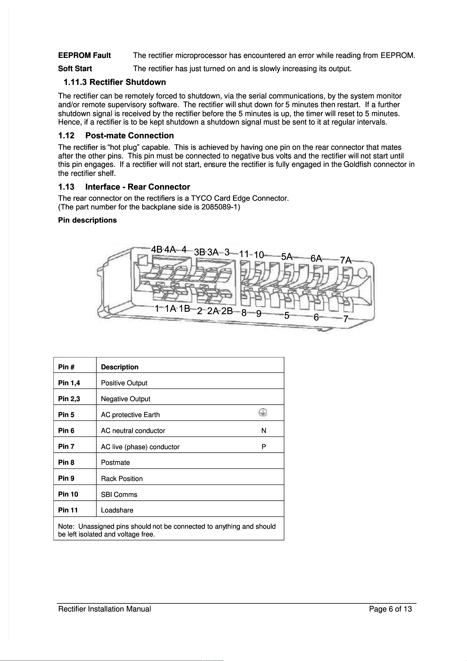
The rear connector on the rectifiers is a TYCO Card Edge Connector.The rear connector on the rectifiers is a TYCO Card Edge Connector.
(The part number for the backplane side is 2085089-1)(The part number for the backplane side is 2085089-1)
Pin descriptionsPin descriptions
88
99
55
66
77
1 1
1A 1A
1B1B
2 2
2A 2A
2B2B
1111
1010
5A5A
6A6A
7A7A
44
BB
44
A A
44
33
BB
33
A A
33
Pin Pin
# #
DescriptionDescription
Pin 1,4Pin 1,4
Positive OutputPositive Output
Pin 2,3Pin 2,3
Negative OutputNegative Output
Pin 5Pin 5
AC protective EarthAC protective Earth
Pin 6Pin 6
AC AC
neutral neutral
conductor conductor
NN
Pin 7Pin 7
AC AC
live live
(phase) (phase)
conductor conductor
PP
Pin 8Pin 8
PostmatePostmate
Pin 9Pin 9
Rack PositionRack Position
Pin 10Pin 10
SBI CommsSBI Comms
Pin 11Pin 11
LoadshareLoadshare
Note: Note:
Unassigned pins should Unassigned pins should
not be connected to anynot be connected to any
thing and shouldthing and should
be left isolated and voltage free.be left isolated and voltage free.

Rectifier Rectifier
Installation Installation
Manual Manual
Page Page
7 7
of of
1313
2 Installation2 Installation
2.1 2.1
General General
WarningsWarnings
This rectifier contains no user serviceable components. Do not disassemble the rectifier.This rectifier contains no user serviceable components. Do not disassemble the rectifier.
To isolate the rectifier from the mains power, simply unplug from the rack or switch off at the distributionTo isolate the rectifier from the mains power, simply unplug from the rack or switch off at the distribution
panel.panel.
2.2 2.2
Rectifier Rectifier
ShelfShelf
The RM848/RM648 rectifiers are designed to be used with the Enatel PSX system.The RM848/RM648 rectifiers are designed to be used with the Enatel PSX system.
2.3 2.3
AC AC
Supply Supply
Surge Surge
ProtectionProtection
The AC supply that feeds the rectifiers should have surge protection installed to meet levels defined forThe AC supply that feeds the rectifiers should have surge protection installed to meet levels defined for
terminal equipment. Enatel recommend that IEC 62305-4(Protection against lightning - Part 4: Electricalterminal equipment. Enatel recommend that IEC 62305-4(Protection against lightning - Part 4: Electrical
and electronic systems within structures) be used to give guidance on the design of surge suppressionand electronic systems within structures) be used to give guidance on the design of surge suppression
systems.systems.
2.4 Ventilation2.4 Ventilation
The performance of the rectifier can be liThe performance of the rectifier can be li
mited if the ventilation is restricted. mited if the ventilation is restricted.
The rectifier is cooled byThe rectifier is cooled by
drawing air into the front of the drawing air into the front of the
unit with a single fan. unit with a single fan.
This air passes through the rectifier cooling theThis air passes through the rectifier cooling the
electronics and exiting the rectifier at electronics and exiting the rectifier at
the rear. the rear.
To ensure this happens as efficiently as To ensure this happens as efficiently as
possible ensure thepossible ensure the
following:following:
The air at the front of the rack is at ambient temperature and not being heated by other equipment.The air at the front of the rack is at ambient temperature and not being heated by other equipment.
Ensure the rectifier shelf has at Ensure the rectifier shelf has at
least 25mm clear horizontal space behind it. least 25mm clear horizontal space behind it.
This space must beThis space must be
clear of cables and any other components that may restrict air movement.clear of cables and any other components that may restrict air movement.
(Note: if multiple rectifier systems are installed then there should be at least 75mm clear horizontal(Note: if multiple rectifier systems are installed then there should be at least 75mm clear horizontal
spacespace
per shelfper shelf
.).)
The free space in the rack should continue vertically to the exhaust point at the top of the rack,The free space in the rack should continue vertically to the exhaust point at the top of the rack,
without impediment.without impediment.
The hot exhaust air should not be allowed to re-circulate to the front of the rack as this will beThe hot exhaust air should not be allowed to re-circulate to the front of the rack as this will be
drawn into the rectifiers again, in effect raising the apparent ambient temperature.drawn into the rectifiers again, in effect raising the apparent ambient temperature.
The rectifier should be operated in a low The rectifier should be operated in a low
dust environment. dust environment.
If this cannot be guaranteed, then the rackIf this cannot be guaranteed, then the rack
should be fitted with air filters to should be fitted with air filters to
prevent dust passing into the rectifier units. prevent dust passing into the rectifier units.
These filters need to beThese filters need to be
designed for adequate air volume and regularly maintained.designed for adequate air volume and regularly maintained.
Note:Note:
If you are designing your own rectifier shelf, then particular care must be taken to ensure that anyIf you are designing your own rectifier shelf, then particular care must be taken to ensure that any
metalwork, cable or printed circuit boards are placed metalwork, cable or printed circuit boards are placed
to maximise the flow of cooling to maximise the flow of cooling
air. air.
To assist in this aTo assist in this a
drawing of the rear area of the rectifier, show air flow areas, has been included in appendix 5.drawing of the rear area of the rectifier, show air flow areas, has been included in appendix 5.
2.5 2.5
Rectifier Rectifier
AddressingAddressing
Each rectifier in the system haEach rectifier in the system ha
s a unique address which identifies it to s a unique address which identifies it to
the monitor. the monitor.
This address is set byThis address is set by
the position in the rectifier shelthe position in the rectifier shel
f and the number of the shelf. f and the number of the shelf.
It is read by the It is read by the
rectifier from the backplanerectifier from the backplane
PCB and will change iPCB and will change i
f the rectifier is moved to a f the rectifier is moved to a
new location. new location.
This address structure is set up when theThis address structure is set up when the
system is built by the system manufacturer.system is built by the system manufacturer.
DANGERDANGER
Do not operate the rectifier if Do not operate the rectifier if
the covers are damaged or removed in any waythe covers are damaged or removed in any way
--
The rectifier contains voltages that may be lethal even after theThe rectifier contains voltages that may be lethal even after the
input supply has been removedinput supply has been removed
--
The rectifier contains components at High Temperatures that The rectifier contains components at High Temperatures that
maymay
burn if touchedburn if touched
Rectifier Rectifier
Installation Installation
Manual Manual
Page Page
8 8
of of
1313
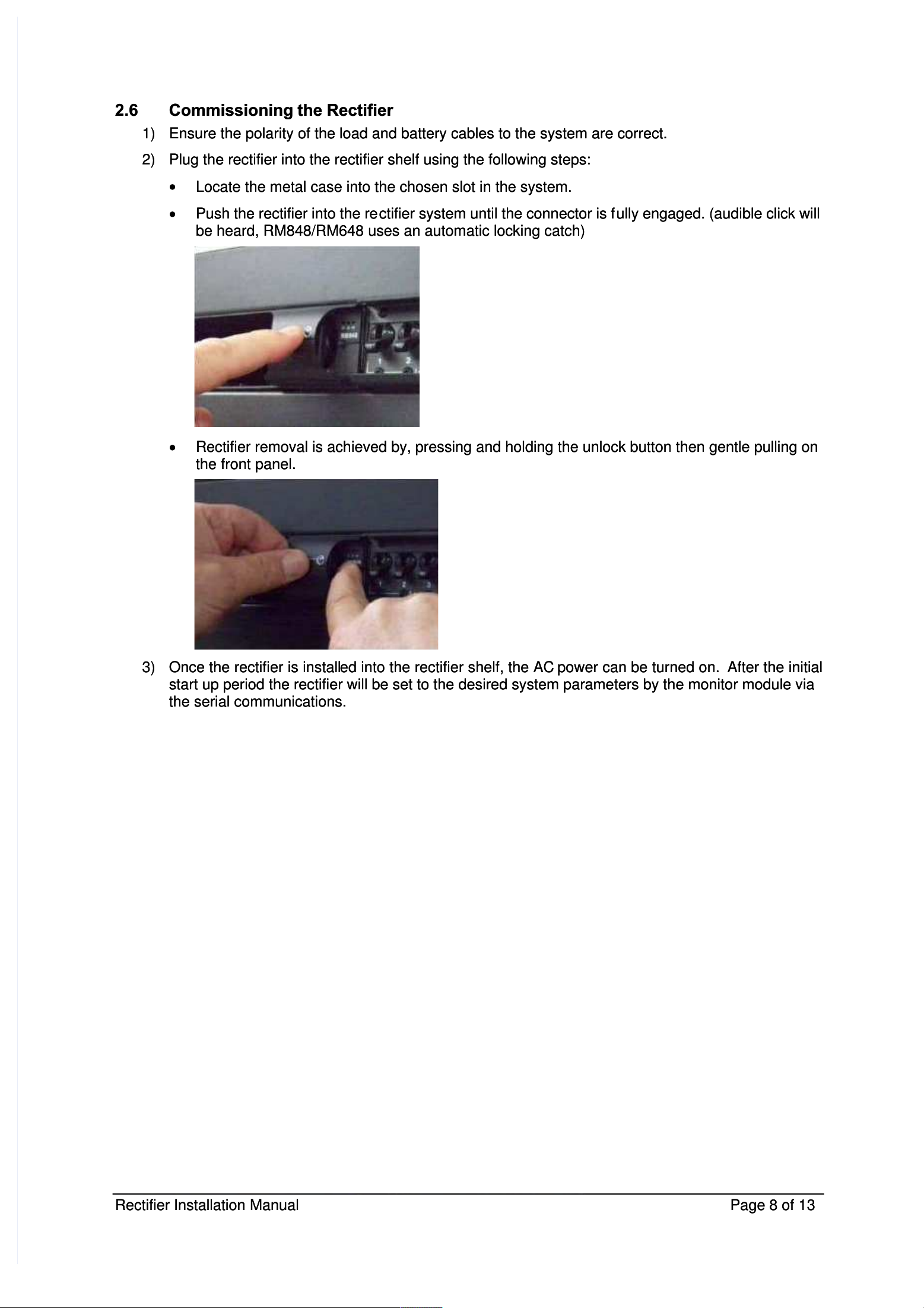
2.6 2.6
Commissioning Commissioning
the the
RectifierRectifier
1)1)
Ensure the polarity of the load and battery cables to the system are correct.Ensure the polarity of the load and battery cables to the system are correct.
2)2)
Plug the rectifier into the rectifier shelf using the following steps:Plug the rectifier into the rectifier shelf using the following steps:
Locate the metal case into the chosen slot in the system.Locate the metal case into the chosen slot in the system.
Push the rectifier into the rePush the rectifier into the re
ctifier system until the connector is fctifier system until the connector is f
ully engaged. (audible click willully engaged. (audible click will
be heard, RM848/RM648 uses an automatic locking catch)be heard, RM848/RM648 uses an automatic locking catch)
Rectifier removal is achieved by, pressing and holding the unlock button then gentle pulling onRectifier removal is achieved by, pressing and holding the unlock button then gentle pulling on
the front panel.the front panel.
3)3)
Once the rectifier is installOnce the rectifier is install
ed into the rectifier shelf, the AC ed into the rectifier shelf, the AC
power can be turned on. power can be turned on.
After the initialAfter the initial
start up period the rectifier will be set to the desired system parameters by the monitor module viastart up period the rectifier will be set to the desired system parameters by the monitor module via
the serial communications.the serial communications.

Rectifier Rectifier
Installation Installation
Manual Manual
Page Page
9 9
of of
1313
3 Specifications*3 Specifications*
3.1 3.1
AC AC
InputInput
NominalNominal
230V 230V
[110V [110V
for for
RM648]RM648]
Voltage RangeVoltage Range
9090
––
300V AC (reduced power below 175V for RM848)300V AC (reduced power below 175V for RM848)
[reduced power below 100V for RM648][reduced power below 100V for RM648]
Frequency RangeFrequency Range
4545
––
66Hz66Hz
Power FactorPower Factor
> >
0.990.99
EfficiencyEfficiency
> >
91% 91%
(>45% (>45%
output output
power)power)
[>88% (>45% output power for RM648)][>88% (>45% output power for RM648)]
Input FusesInput Fuses
HRC HRC
Fuses Fuses
in in
phase phase
and and
neutralneutral
Maximum Input CurrentMaximum Input Current
5.1A5.1A
[6.7A for RM648][6.7A for RM648]
ProtectionProtection
Input VoltageInput Voltage
Automatic Automatic
shutdown, shutdown,
restarts restarts
when when
correct correct
voltage voltage
restored.restored.
Input InrushInput Inrush
< <
2 2
times times
Maximum Maximum
Input Input
CurrentCurrent
3.2 3.2
DC DC
OutputOutput
NominalNominal
48V 48V
Rated VoltageRated Voltage
54V 54V
Adjustable Voltage RangeAdjustable Voltage Range
43V 43V
––
58V58V
Maximum Rated CurrentMaximum Rated Current
16.6A 16.6A
[12.5A for RM648][12.5A for RM648]
Maximum Rated PowerMaximum Rated Power
0.8kW 0.8kW
[0.6kW for RM648][0.6kW for RM648]
RegulationRegulation
LineLine
±0.1% ±0.1%
LoadLoad
±0.5% ±0.5%
no no
load load
to to
full full
loadload
Hold-up timeHold-up time
>15ms >15ms
for for
20% 20%
output output
voltage voltage
dropdrop
Start-up timeStart-up time
Start-up Start-up
delay delay
1 1
second. second.
(varies (varies
with with
AC AC
supply supply
voltage)voltage)
Walk-in delay 6 seconds at full output. (varies with DC output voltage)Walk-in delay 6 seconds at full output. (varies with DC output voltage)
ProtectionProtection
Power LimitPower Limit
Adjustable Adjustable
to to
5050
––
100% of maximum rated current100% of maximum rated current
Over TemperatureOver Temperature
Automatic Automatic
current current
turndown, turndown,
backup backup
shutdown shutdown
protectionprotection
Polarity ReversalPolarity Reversal
Output Output
Fuse Fuse
with with
Crowbar Crowbar
diode diode
in in
back back
planeplane
Over VoltageOver Voltage
Adjustable Adjustable
limitlimit
NoiseNoise
RippleRipple
Below Below
100Hz 100Hz
<1mV<1mV
RMSRMS
UnweightedUnweighted
Voice bandVoice band
100Hz 100Hz
to to
5 5
kHz kHz
<2mV<2mV
RMSRMS
PsophometricPsophometric
Wide bandWide band
5 5
kHz kHz
to to
1MHz 1MHz
<5mV<5mV
RMSRMS
UnweightedUnweighted
Peak to PeakPeak to Peak
0 0
to to
20MHz 20MHz
<50mV <50mV
Peak Peak
to to
peakpeak
IsolationIsolation
Input to outputInput to output
4000V 4000V
DCDC

Rectifier Rectifier
Installation Installation
Manual Manual
Page Page
10 10
of of
1313
Input to ChassisInput to Chassis
3500V 3500V
DC DC
(VDR (VDR
to to
chassis chassis
removed)removed)
Output to ChassisOutput to Chassis
2100V 2100V
DCDC
3.3 Environmental3.3 Environmental
Operating Ambient TemperatureOperating Ambient Temperature
RatedRated
25± 25±
5 5
ºCºC
RangeRange
-10ºC -10ºC
to to
50ºC50ºC
HumidityHumidity
55
––
95% RH (non-condensing)95% RH (non-condensing)
Altitude <Altitude <
2500m above sea level2500m above sea level
De-rate maximum ambient temperatureDe-rate maximum ambient temperature
by 4ºC per 1000m above sea level.by 4ºC per 1000m above sea level.
3.4 Mechanical3.4 Mechanical
Dimensions Dimensions
(W, (W,
H, H,
D) D)
55mm 55mm
, ,
44 44
(1U), (1U),
260mm 260mm
overall overall
(245mm (245mm
shelf)shelf)
Weight 635gWeight 635g
Shipping Dimensions Shipping Dimensions
(W, H, (W, H,
D) D)
60mm, 52mm, 325mm60mm, 52mm, 325mm
Shipping Shipping
Weight Weight
800g800g
3.5 Compliances3.5 Compliances
Safety EN60950Safety EN60950
Electrostatic Electrostatic
Discharge Discharge
CISPR CISPR
2424
Radiated Radiated
Radio Radio
Frequency Frequency
CISPR CISPR
2222
AC AC
Harmonics Harmonics
EN EN
61000-3-261000-3-2
AC AC
Flicker Flicker
and and
Fluctuation Fluctuation
EN EN
61000-3-361000-3-3
Other Other
CE CE
& &
RoHS RoHS
compliantcompliant
Due to ongoing product development specifications are subject to change without prior notice.Due to ongoing product development specifications are subject to change without prior notice.
* Note: The specifications cover both rectifiers RM848 and low power version RM648, where* Note: The specifications cover both rectifiers RM848 and low power version RM648, where
specifications differ between rectifiers, the specifications differ between rectifiers, the
RM648 rectifier specifications are specified in tRM648 rectifier specifications are specified in t
hehe
parenthesis i.e. [ ].parenthesis i.e. [ ].
Rectifier Rectifier
Installation Installation
Manual Manual
Page Page
11 11
of of
1313
4 Servicing4 Servicing
If the rectifier develops an operational fault, or is damaged in any way, an Authorised Service CentreIf the rectifier develops an operational fault, or is damaged in any way, an Authorised Service Centre
should service it immediately.should service it immediately.
4.1 Warnings4.1 Warnings
This This
rectifier rectifier
contains contains
no no
user user
serviceable serviceable
components. components.
Do Do
not not
disassemble the disassemble the
rectifier.rectifier.
4.2 Troubleshooting4.2 Troubleshooting
If If
the the
red red
LED LED
is is
alightalight
::
Unplug the rectifier and re-engage.Unplug the rectifier and re-engage.
Check AC power to the rectifier.Check AC power to the rectifier.
Check for rectifier alarms in the monitor Urgent Alarm list.Check for rectifier alarms in the monitor Urgent Alarm list.
If symptoms persist, contact a service agent.If symptoms persist, contact a service agent.
If If
the the
yellow yellow
LED LED
is is
alight:alight:
Check the monitor Non-Urgent Alarm list.Check the monitor Non-Urgent Alarm list.
4.3 Fuses4.3 Fuses
Although there are fuses inside the rectifier, these are rated such that their failure indicates a fault requiringAlthough there are fuses inside the rectifier, these are rated such that their failure indicates a fault requiring
qualified service.qualified service.
Do not attempt to repair these fuses.Do not attempt to repair these fuses.
However for IEC 60950 the fuse ratings are required to be specified. The following fuses are soldered toHowever for IEC 60950 the fuse ratings are required to be specified. The following fuses are soldered to
the PCB:the PCB:
FH100FH100
10A 250V ceramic slow blow wire end Fuse10A 250V ceramic slow blow wire end Fuse
FH101FH101
10A 250V ceramic slow blow wire end Fuse10A 250V ceramic slow blow wire end Fuse
DANGERDANGER
Do not operate the rectifier if the covers are Do not operate the rectifier if the covers are
damaged or removed in any way.damaged or removed in any way.
--
The rectifier contains voltages that may be lethal even after the input supplyThe rectifier contains voltages that may be lethal even after the input supply
has been removedhas been removed
--
The rectifier contains components at High The rectifier contains components at High
TemperatureTemperature
s that may s that may
causecause
burns if touchedburns if touched

Rectifier Rectifier
Installation Installation
Manual Manual
Page Page
12 12
of of
1313
5 5
Ventilation Ventilation
DetailsDetails
Rear view of rectifiers, the RM848/RM648 is designed for fitting into a Enatel PSX systems. TheseRear view of rectifiers, the RM848/RM648 is designed for fitting into a Enatel PSX systems. These
systems allow for the flow path of the exit air form the rectifier.systems allow for the flow path of the exit air form the rectifier.
Rectifier Rectifier
Installation Installation
Manual Manual
Page Page
13 13
of of
1313
6 Warranty6 Warranty
Enatel Ltd. warrants that this product is free from defects in material and workmanship and agrees toEnatel Ltd. warrants that this product is free from defects in material and workmanship and agrees to
remedy any defect (or at its option replace the product) for a period of one year from the date of purchase.remedy any defect (or at its option replace the product) for a period of one year from the date of purchase.
This warranty covers both parts and labour. Parts may be replaced under this warranty with new orThis warranty covers both parts and labour. Parts may be replaced under this warranty with new or
remanufactured parts.remanufactured parts.
This warranty will not apply to any product that has been improperly installed (as described in theThis warranty will not apply to any product that has been improperly installed (as described in the
installation manual), misused, abused, used in ways the product was not designed, altered or repaired ininstallation manual), misused, abused, used in ways the product was not designed, altered or repaired in
any way which may affect the performance or reliability of operation, sustained damage by power surgesany way which may affect the performance or reliability of operation, sustained damage by power surges
or electrical storms, or sustained shipping damage, or repaired by any unauthorised repair centre.or electrical storms, or sustained shipping damage, or repaired by any unauthorised repair centre.
Please contact Enatel Customer Service to obtain a Returned Materials Authorisation (RMA) prior toPlease contact Enatel Customer Service to obtain a Returned Materials Authorisation (RMA) prior to
shipping any products for repair. All shipments must be shipped prepaid and include proof of the date ofshipping any products for repair. All shipments must be shipped prepaid and include proof of the date of
your original purchase. Please include your name, address, phone number, email address and a briefyour original purchase. Please include your name, address, phone number, email address and a brief
description of the problem.description of the problem.
Enatel Ltd makes no other warranties, express or implied, including any warranty of fitness for a particularEnatel Ltd makes no other warranties, express or implied, including any warranty of fitness for a particular
purpose. In no event shall Enatel be responsible for indirect or consequential damages or lost profits evenpurpose. In no event shall Enatel be responsible for indirect or consequential damages or lost profits even
if Enatel Ltd has been advised of the possibility of such damages. Enatel Ltd’s sole obligation to you shallif Enatel Ltd has been advised of the possibility of such damages. Enatel Ltd’s sole obligation to you shall
be the repair or replacement of a non-conforming product.be the repair or replacement of a non-conforming product.
This manual suits for next models
1
Table of contents
Other Enatel Power Supply manuals


Popular Power Supply manuals by other brands

Lucent Technologies
Lucent Technologies Galaxy Power System 4812 product manual

Sanela
Sanela SLZ 04X manual

ITS Telecom
ITS Telecom EKSELANS AM 361 EASY MAGNEK quick start guide

Monacor
Monacor PSS-3800SV operating instructions

Puls
Puls DIMENSION UF Series manual

dol sensors
dol sensors iDOL 65 Technical user guide


