Enatel RW312U User manual

Installation and Operation
Manual
Model:
RW312U, RW324U, RW348U RW512U, RW517U, RW624U, RW748U
Series Rectifiers
Version 3.6
Enatel DC System Manual

Enatel 66 Treffers Road Christchurch 8042 New Zealand
Ph: +64 3 366 4550 | Fax: +64 3 366 0884 | Email: sales@enatel.net | http://www.enatel.net
Warranty
Enatel provides a one year limited warranty, details as stated under the manual section
Appendix I Enatel Energy Standard Limited Warranty Policy on page 22.
System Compliance
Low Voltage Directive (LVD) 2014/35/EU
Electromagnetic Compatibility Directive (EMC) 2014/30/EU
Copyright © Enatel 2020
All rights reserved.
Release Date: 29 May 2020
Disclaimer: Enatel reserves the right to make changes to the information within this document
without notice.
Enatel Energy® is a registered trademark of Enatel. All other trademarks are acknowledged as
belonging to their respective owners.

Enatel DC System Manual
Page 3of 26
Model: RWxxx
Version: 3.6
TABLE OF CONTENTS
1Safety....................................................................................................................................................... 5
2Introduction ..........................................................................................................................................5
2.1 LEDs .................................................................................................................................................6
2.2 Display ............................................................................................................................................6
2.3 Auto Float Boost .........................................................................................................................6
2.4 Low Voltage Disconnect and Reset (Optional)................................................................7
2.5 Temperature Compensation ..................................................................................................7
2.6 Current Limit.................................................................................................................................8
2.7 Output Over Voltage Shut Down .........................................................................................8
2.8 Input Over Voltage Shut Down.............................................................................................8
2.9 Input Inrush Current Limiter ...................................................................................................8
2.10 Over Temperature Shutdown ................................................................................................8
2.11 Reverse Polarity Protection.....................................................................................................8
2.12 Parallel Rectifier Operation .....................................................................................................8
2.13 External Shutdown .....................................................................................................................9
2.14 Alarm & Control Interface .......................................................................................................9
2.15 Internal Alarm Card (Optional)..............................................................................................9
3Installation ........................................................................................................................................... 10
3.1 General Warnings..................................................................................................................... 10
3.2 Rectifier Positioning................................................................................................................. 10
3.3 Cabling.......................................................................................................................................... 12
3.4 Temperature Compensation ................................................................................................ 13
3.5 Multiple Rectifiers..................................................................................................................... 13
3.6 Internal Alarm Card (Optional)............................................................................................ 14
3.7 Relays ............................................................................................................................................ 14
3.8 Rectifier Fail/Mains Fail........................................................................................................... 15
3.8.1 Rectifiers in Parallel....................................................................................................... 15
4Commissioning the Rectifier......................................................................................................... 16
5Servicing............................................................................................................................................... 16
5.1 Warnings...................................................................................................................................... 16
5.2 Troubleshooting........................................................................................................................ 17
5.3 Fuses.............................................................................................................................................. 17
6Setting Changes ................................................................................................................................ 18
6.1 Default Settings........................................................................................................................ 20

Enatel DC System Manual
Page 4of 26
Model: RWxxx
Version: 3.6
6.2 Adjust Float Voltage ............................................................................................................... 20
6.3 Adjust Boost Voltage.............................................................................................................. 20
6.4 Adjust Boost to Float Current Threshold ........................................................................ 20
6.5 Adjust Current Limit................................................................................................................. 21
6.6 Adjust Over-Voltage Shutdown.......................................................................................... 21
6.7 Adjust Low Voltage Disconnect and Hysteresis............................................................ 21
6.8 Adjust Temperature Compensation Slope..................................................................... 22
6.9 Adjusting the alarm output volt low/high setting ....................................................... 22
Appendix I Enatel Energy Standard Limited Warranty Policy................................................... 22
I.A Warranty Exclusions and Restrictions............................................................................... 23
I.B Battery Warranty...................................................................................................................... 23
I.C Initiating a Warranty Claim .................................................................................................. 23
I.DDisclaimer................................................................................................................................... 24
I.E Remark......................................................................................................................................... 24
TABLE OF FIGURES
Figure 1: Rectifier Mounting ..................................................................................................................11
Figure 2: Rectifier View............................................................................................................................11
Figure 3: Cabling Architecture............................................................................................................. 12
Figure 4: DC Connector ......................................................................................................................... 13
Figure 5: Alarm Contacts....................................................................................................................... 14
Figure 6: Alarm Configuration............................................................................................................. 15
Figure 7: Trimpot Access ....................................................................................................................... 19
Figure 8: Trimpot Functions ................................................................................................................. 19
LIST OF TABLES
Table 1: RW Models...................................................................................................................................5
Table 2: Low Voltage Disconnect.........................................................................................................7
Table 3: Pin descriptions..........................................................................................................................9
Table 4: Fuse specifications by model:............................................................................................. 18
Table 5: Default Settings....................................................................................................................... 20

Enatel DC System Manual
Page 5of 26
Model: RWxxx
Version: 3.6
1SAFETY
All installation and maintenance must be carried out by
suitably qualified personnel.
For your protection, the product manual should be read and
thoroughly understood before unpacking, installing and
using the equipment.
2INTRODUCTION
The RW range of freestanding convection cooled wall-mount rectifiers consists of the
following models:
Table 1: RW Models
Model Input Volts Max Input
Current
Nominal
Voltage
Rated
Voltage
Voltage
Range
Maximum
Current
Power
Rating
RW312U 110 – 240V 4A 12V 13.7V 11.5-15V 20A 300W
RW324U 110 – 240V 4A 24V 27.4V 22-30V 10A 300W
RW348U 110 – 240V 4A 48V 54.0V 45-60V 6A 300W
RW512U 110 – 240V 8.5A 12V 13.7V 11.5-15V 35A 500W
RW517U 110 – 240V 8.5A 17V 17.4V 13-17.6 26A 500W
RW624U
110 – 240V 8.5A 24V 27.4V 22-30V 22A 600W
RW748U 110 – 240V 4A 48V 54.0V 45-60V 12A 700W
The features of the rectifiers are:
•Convection Cooled
•Thermal Protection
•Power Factor Corrected
•Input/Output Voltage and Current
Protected
•Temperature Compensation
•Built in LVD - Battery Low Voltage
Disconnect (Option)
•Automatic Boost/Float Charge cycle
•Active Load Sharing when operated
in parallel with another rectifier
•External Alarm and Control interface
(Option)
•Bar Graph Current Indicator
•Integrated Alarm Outputs (Option)

Enatel DC System Manual
Page 6of 26
Model: RWxxx
Version: 3.6
Custom configurations of the rectifier are available for specific requirements, and some
features may not be (or extra features may be) present in each unit.
2.1 LEDs
There are 4 LEDs that indicate the operational state of the rectifier. These LEDs can be
used to determine the present state of the rectifier and diagnose faults.
Mains On:
•This LED glows green to indicate that mains power is connected to the unit and
that the primary stages of the rectifier are operating.
Off Normal LED:
•Yellow – Rectifier in “Current Limit”
•Red – Rectifier shutdown through over voltage or over temperature.
Float/Boost LED:
•Green – Rectifier operating in “Float Charge” mode
•Yellow – Rectifier operating in “Boost Charge” mode
Temperature Probe LED:
•Green – Temperature Compensation Probe connected and within limits
•Red – Rectifier has failed– also lights if the output voltage is externally forced
above the rectifier output voltage + 4.5%. Powered from the battery. Off if the
LVD has tripped.
NOTE: if the Temperature Compensation Probe is connected and the rectifier fails, the LED
may not show. The monitor external signals are still correct. To verify the condition,
unplug the Temperature Compensation Probe.
2.2 Display
A row of LEDs on the front panel indicates the approximate percentage current output
from the rectifier (only 1 LED is lit at any one time). So if the 60% LED is displayed on a RW
312 rectifier, then the current being drawn from the rectifier is 60% of 20A = 12Amps.
2.3 Auto Float Boost
When the rectifier is powered on, the rectifier starts in Boost Charge mode. If the battery
charge current is above the Boost to Float Current threshold, it will stay in Boost Charge
mode. When the battery charge current falls below the Boost to Float Current threshold
for more than 10 seconds, it will switch to Float Charge mode. If for some reason the
battery charge current rises above the Boost to Float Current threshold, the rectifier will
switch back into Boost Charge mode (there is no time delay).
A Boost Timer limits the time the rectifier stays in Boost Charge mode. While the rectifier
is in Boost Charge mode and in Current Limit, the Boost Timer is inhibited. When the
rectifier comes out of Current Limit, the Boost Timer starts and will automatically switch
Enatel DC System Manual
Page 7of 26
Model: RWxxx
Version: 3.6
the rectifier into Float Charge mode after about 4 hours, even if the battery current
remains above the Boost to Float Current threshold.
The Boost and Float voltages are pre-set in the factory but may be adjusted to suit the
specific battery installation.
2.4 Low Voltage Disconnect and Reset (Optional)
The Low Voltage Disconnect (LVD) feature is designed to protect the battery from deep
discharge when the battery is supplying the load current (i.e. mains is off, or the load is
drawing more than the rectifier capacity).
The rectifier monitors the battery voltage when the battery is supplying current, and
disconnects the load from the battery when the battery voltage falls to a pre-set level.
When the battery voltage has increased above the LVD Hysteresis voltage the load is
automatically reconnected back to the battery.
The LVD may be manually reset when it has activated by pressing the LVD Reset button
on the front of the rectifier.
The LVD switches the battery +ve supply (the -ve is common with the battery). Do not
connect the Battery and Load +ve together.
The LVD voltage and the LVD Hysteresis voltage are pre-set in the factory, but may be
adjusted to suit the specific battery installation.
Table 2: Low Voltage Disconnect
Model
Voltage Adjustment Range
Maximum Load Current
RW312U
9.5 to 12V
20A
RW324U
19 to 24V
10A
RW348U
38 to 48V
6A
RW512U
9.5 to 12V
35A
RW517U
9.5 to 12V
26A
RW624U
13 to 17.6V
22A
RW748U
38 to 48V
12A
Do NOT exceed the maximum load current, as the rectifier LVD circuitry may be
damaged. The LVD circuitry is protected by shutting down if its circuitry is overheated due
to over current conditions. Excessive overloading will cause an internal protection fuse to
rupture.
If the LVD functionality is not required, the load must be connected to the Load
connection (not directly onto the battery). That is, connect all Load & battery connections
to load terminal only. Note the Auto Float Boost functionality is lost and the battery
subject to complete drain.
2.5 Temperature Compensation
Batteries require different charging voltages depending on the ambient temperature of
the battery. The colder the battery, the higher the voltage required to charge the battery.

Enatel DC System Manual
Page 8of 26
Model: RWxxx
Version: 3.6
The battery temperature is measured by connecting a Temperature Compensation Probe
(available separately) to one of the battery terminals. The rectifier will then automatically
adjust the charging voltage.
The Temperature Compensation Slope is pre-set in the factory but is adjustable from 0.1%
to 0.2% change in charge voltage per degree C.
If the Temperature Compensation Probe is not connected, then the rectifier will assume a
battery temperature of 25°C.
2.6 Current Limit
The rectifier automatically limits the rectifier output current. The maximum output current
is pre-set in the factory but may be adjusted down.
2.7 Output Over Voltage Shut Down
The rectifier will automatically shutdown if the output voltage exceeds the pre-set value.
The Over Voltage Shutdown voltage is pre-set in the factory but may be adjusted.
2.8 Input Over Voltage Shut Down
If the input voltage is outside the specified range, the rectifier may shut down until the
allowed voltage is restored.
2.9 Input Inrush Current Limiter
On start-up, the peak mains inrush current is limited to twice the maximum operating
current. The output voltage and current rise slowly from zero during start-up.
2.10 Over Temperature Shutdown
When the rectifier reaches its maximum operating temperature, the rectifier will
progressively reduce the output current to attempt to reduce the heat within the unit. In
extreme circumstances, the rectifier will totally shutdown.
The maximum operating temperature range is:
Model
Temperature
312U, 324U, 348U
-10 to 65°C
512U, 517U, 624U, 748U
-10 to 50°C
2.11 Reverse Polarity Protection
The rectifier has an internal reverse polarity protection fuse and crowbar diode fitted.
These parts are not user serviceable, and the rectifier will require returning for servicing if
they fail.
2.12 Parallel Rectifier Operation
The rectifiers may be connected in parallel to source more current, or to provide a degree
of redundancy. The rectifiers should have the load share signal connected between the
rectifiers. This is achieved by connecting the load share signal line on the Alarm & Control

Enatel DC System Manual
Page 9of 26
Model: RWxxx
Version: 3.6
Interface port on each rectifier. The rectifiers with the higher voltage output will
automatically adjust their output voltage down so that they each take a uniform share of
the load.
The rectifiers connected in parallel must all be of the same brand and voltage rating.
Different power ratings can be combined, a 300W model may be connected in parallel
with a 600W model (e.g. a 324 with a 624).
2.13 External Shutdown
The rectifier can be remotely forced to shutdown by applying a positive 10-12V signal to
the rectifier load share pin of the Monitor connector. (With respect to –ve battery/load
common)
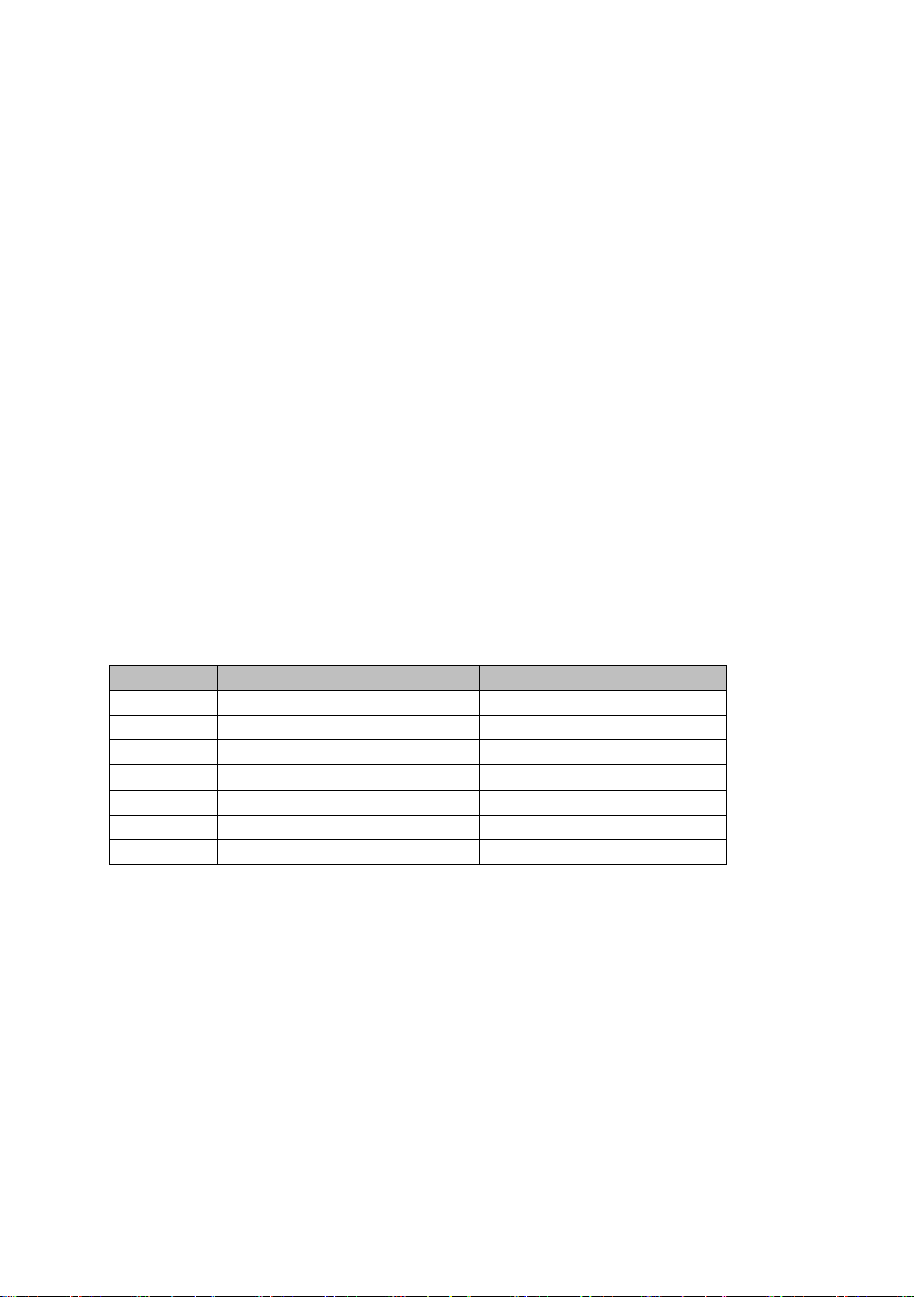
2.14 Alarm & Control Interface
The monitor connection allows remote monitoring of the rectifier. The monitor
connection is a RJ45 socket. The pinout of the socket is as follows:
Table 3: Pin descriptions
Pin #
Description
Pin 1
Load Share signal (0-5V), external shutdown (10-12V in)
Pin 2
LVD Synch signal
Pin 3
Temp Comp Probe/Output Voltage Control
Pin 4
Rectifier Failed Signal – Pulls to ground via 4k7 resistor
Pin 5
-ve for Temp Comp Probe (signal Gnd)
Pin 6
Rectifier “Off Normal” alarm (open collector output)
Pin 7
+V Battery Out (max 250mA)
Pin 8
Mains fail (open collector output) (off = mains present)
2.15 Internal Alarm Card (Optional)
The internal alarm card may be fitted to a rectifier. The alarm card provides voltage free
relay contacts in the event of:
•Mains failure
•Rectifier failure
•Rectifier Off Normal (over temperature, over voltage, current limit)
•High voltage output
•Low voltage output
1
Pin 1 is the left most pin, when facing
the socket with the pins on the bottom.

Enatel DC System Manual
Page 10 of 26
Model: RWxxx
Version: 3.6
When rectifiers are connected in parallel using an RJ45 cable to connect between the
alarm and control interface on each rectifier, the alarm outputs on the Alarm Card give
the status of all the connected units. This means that only one alarm card needs to be
connected to the alarm circuitry when the rectifiers are connected in parallel
3INSTALLATION
3.1 General Warnings
This rectifier contains no user serviceable components. Do not disassemble the rectifier.
To isolate the rectifier from the mains power, unplug the IEC mains connector from the
rectifier.
DANGER Do not operate the rectifier if the covers are damaged
or removed in any way.
WARNING The rectifier contains voltages that may be lethal even
after the input supply has been removed.
WARNING The rectifier contains components at high temperature
that may burn if touched
3.2 Rectifier Positioning
Caution
The rectifier is convection cooled and MUST be mounted correctly.
It must be on a vertical surface (wall), perpendicular to the floor.
It must be mounted in a “landscape” orientation with side
connectors on the right.
Do not mount rectifiers above each other.
Observe all instructions on the rectifier.

Enatel DC System Manual
Page 11 of 26
Model: RWxxx
Version: 3.6
Figure 1: Rectifier Mounting
(Photo for reference only. Actual product may vary)
The rectifier is convection cooled and MUST be mounted correctly.
The rectifier should be positioned close to the load and batteries, so as to keep the length
of the low voltage cables to a minimum. These cables are carrying high currents, and
voltage drop in the cables must be kept to a minimum. It is better to have a long mains
lead and short low voltage cables.
The rectifier must be positioned so that airflow through the rectifier is not impeded in any
way. These rectifiers are convection cooled – their performance and life expectancy is
reduced if the airflow is impeded.
The rectifier should not be mounted above another rectifier or a source of heat.
The rectifier should be mounted 50mm clear of any other solid object, and care should be
taken to ensure that air entering the rectifier is cool air and has not been heated by other
equipment.
Figure 2: Rectifier View
Connectors
on right side
of rectifier
Enatel DC System Manual
Page 12 of 26
Model: RWxxx
Version: 3.6
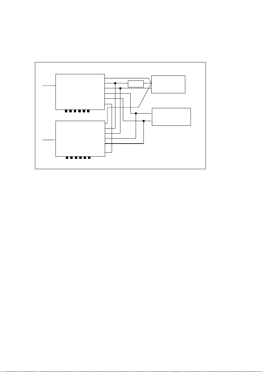
3.3 Cabling
It is important that all cables (except mains) are less than 3m in length. The rectifier is not
designed for cables greater than 3m or for connection to outside cables.
Figure 3: Cabling Architecture
Mains: The length of the mains cable to the rectifier is not critical. The rectifiers only draw
300W or 700W and they will accept a wide range of input voltages. The mains cable to
the rectifier should be switched at its supply, so the rectifier can be isolated for installation
or servicing. It is recommended that a switched permanent outlet be used, so the rectifier
will not be accidentally unplugged from the supply.
Load and Battery: Standard length cables are available from the rectifier supplier. It is
important that the lengths of these cables are kept to a minimum to reduce voltage drop
(the length of the cables should be adjusted). A fuse MUST be installed between the
battery and the rectifier, to protect the rectifier, load and battery. The fuse should be
mounted close to the battery, and have a high rupture current capability just above the
rectifier capability. This fuse protects the wiring and the rectifier from over current.
If the LVD functionality is not required, the load must still be connected to the Load
connection (not directly onto the battery). That is, connect all Load & battery connections
to load terminal only. Note the Auto Float Boost functionality is lost and the battery
subject to complete drain.
When custom made load and battery wires are used for most applications it is mandatory
that two wires are run in parallel for both the +ve and –ve Battery and Load connections.
1.5mm2 wire should be used for the connectors. In situations where voltage drop is a
concern, then a short length of 1.5mm2 wire should be used from the rectifier, connecting
to a longer length of large cross section wire. Connectors supplied for the rectifier are 4W
Batteries
Load
+
-
+
-
+
-
+
-
-
Fuse
+
-
+
-
Alarm Contacts
Load
Battery
Load Share/Monitor
Temp Comp
Mains
Alarm Contacts
+
-
+
-
Load
Rectifiers
Battery
Load Share/Monitor
Temp Comp
Mains
+
-
+
-

Enatel DC System Manual
Page 13 of 26
Model: RWxxx
Version: 3.6
Lumberg IDC connectors (insulation displacement). Each terminal on the connector is
rated at 16Amps at 50°C.
To crimp the cable into the connector, simply insert the correct wire into the connector,
and squeeze the connector in a vice or with a small press. Vice grips can be used
provided a metal plate is used either side of the connection to protect the plastic. Once
the connector has been crimped, it cannot be reused, so take great care to make sure
that the correct wire and polarity colour is inserted before crimping. Additional spare
connectors are available from the rectifier supplier.
Figure 4: DC Connector
3.4 Temperature Compensation
Temperature Compensation Probes are available in different lengths. The end of the
Temperature Compensation Probe should be attached to a terminal on a battery (the lug
is isolated, so it doesn’t matter which terminal). Any excess cable should be neatly coiled.
As the current in the Temperature Compensation Probe is minimal, it does not matter if
the cable is longer than necessary (unlike the current carrying load and battery cables).
Caution Do not reverse the polarity of the cables from the battery.
This will blow an internal protection fuse, requiring the
rectifier to be returned for servicing
Do not connect the Temperature Compensation Probe to the rectifier until
commissioning. See 4Commissioning the Rectifier.
3.5 Multiple Rectifiers
The rectifiers may be operated in parallel to provide greater current capability and to
provide redundancy.
When rectifiers are connected in parallel (and load sharing), alarm outputs on the
rectifiers give the status of all the units. This means that you only need to connect one
alarm card to the alarm circuitry when the rectifiers are connected in parallel.
The load and battery cables should be wired in parallel to the rectifiers as per the diagram
in section 2.3. Each rectifier should be fitted with a Temperature Compensation Probe
connected to the same terminal on the same battery.
For load and alarm sharing, an alarm and control interface cable should be connected to
each parallel rectifier to ensure that all rectifiers load share automatically. When two or
DC Connector
4 Way Lumberg layout (viewed facing the front of the plug)

Enatel DC System Manual
Page 14 of 26
Model: RWxxx
Version: 3.6
more units are connected in parallel, then you can use a simple RJ45 double adaptor to
daisy chain the connection cable (max 6 rectifiers).
Any fuses or circuit breakers on the output of the rectifier must be placed after the
rectifier outputs have been connected together.
3.6 Internal Alarm Card (Optional)
The internal alarm card may be fitted to a rectifier. The alarm card provides voltage free
relay contacts in the event of:
•Mains failure
•Rectifier failure
•Rectifier Off Normal (over temperature, over voltage, current limit)
•High voltage output
•Low voltage output
When rectifiers are connected in parallel using an RJ45 cable to connect between the
alarm and control interface, the alarm outputs on the Alarm Card give the status of all the
connected units. This means that you only need one alarm card needs to be connected to
the alarm circuitry when the rectifiers are connected in parallel.
The diagram Figure 5: Alarm Contacts describes the alarm contacts found on the front
panel of the unit.
Figure 5: Alarm Contacts
Refer to section 6.9 Adjusting the alarm output volt low/high setting for information on
adjusting the alarm output volt low/high settings.
3.7 Relays
The relays are Single Pole Double Throw (or changeover). Both Normally Closed (NC) and
Normally Open (NO) contacts are provided. Contact rating is 100v DC, 1A max and all
Common contact for all alarms
(except Mains Fail)
NC = Normally Closed
NO = Normally Open
Clean contacts for Mains Fail status

Enatel DC System Manual
Page 15 of 26
Model: RWxxx
Version: 3.6
contacts are isolated from the rectifiers’ internal circuitry. Do NOT connect AC supply to
the relays.
When the rectifier is operating normally (ie with no fault, or abnormal conditions) the
relay outputs designated NC will be connected to the common terminal, and the relay
outputs designated NO will be open circuit. Upon an alarm condition occurring the NO
contacts will be connected to the common terminal, and the NC contacts will be open
circuit.
The internal alarm card is powered from the batteries connected to the rectifier. This
allows the alarm card to operate correctly even when the mains have failed.
If the rectifier does not have a battery connected and the mains fails, then the Mains Fail
relay still reflects the state of the mains, however the Rectifier Fail alarm, Rectifier Off
Normal and the Low Volts alarms will also activate.
NOTE:the Mains Fail Relay has its own “Common” connector, but all the other alarm
outputs share a “Common” contact.
3.8 Rectifier Fail/Mains Fail
The Mains Fail Alarm is activated while the mains power is not present.
The Rectifier Fail Alarm can be configured to activate when the mains has failed (as well as
when the Rectifier Fails). Alternatively, the Rectifier Fail can be configured to not activate if
the mains fails, so that you can remotely determine if the problem is the mains failure or a
rectifier failure.
To select between the two options set the jumper located on the rear of the rectifier. The
parameters for the Alarm Output Volt Low and High setting can be adjusted by the
trimpots next to the jumper. See Figure 6: Alarm Configuration for details.
Figure 6: Alarm Configuration
3.8.1 Rectifiers in Parallel
The internal alarm cards of multiple parallel rectifiers can be connected in parallel so that
the alarm condition can be reported if any alarm is triggered in any rectifier.
When rectifiers are connected in parallel (and load sharing), the alarm outputs on the
rectifiers give the status of all the units in parallel. This means that you only need to
connect one alarm card to the alarm circuitry when the rectifiers are connected in parallel.

Enatel DC System Manual
Page 16 of 26
Model: RWxxx
Version: 3.6
4COMMISSIONING THE RECTIFIER
1. Make sure that all cables and wires are disconnected from the rectifier.
2. Plug the Mains cable into the rectifier and switch the mains on at the outlet. The
Mains LED should glow green.
3. Disconnect the mains, then plug in the Temperature Compensation Probe, re-
connect the mains and check that the Temperature Probe LED is green.
4. Disconnect the mains, then double check the polarity of the cables from the
battery (there should be an HRC fuse in the battery lead as close as possible to
the battery to protect the wiring from faulty connections) and then plug them
into the rectifier. Re-connect the mains and the Float Boost LED should glow first
yellow then after about 10 seconds either green or yellow depending on the
charge of the battery. The display LEDs should give an indication of the current
from the rectifier.
5. Disconnect the mains, then double check the polarity of the cables to the load,
and then plug them into the rectifier. Re-connect the mains.
6. If there is more than one rectifier connected in parallel, then follow the above
procedure for each rectifier in turn (with the other rectifiers all disconnected).
Ensure all rectifiers are adjusted to the same output voltage (better than ±0.1V)
Finally connect the Load Share Signal cable between the rectifiers, and check
that all rectifiers are indicating near equal current (should be better than 10% of
full load).
7. Connect the alarms (if fitted/used) and check their operation.
5SERVICING
If the rectifier develops an operational fault or is damaged in any way an Authorised
Service Centre should service it immediately.
5.1 Warnings
This rectifier contains no user serviceable components. Do not disassemble the rectifier.
To isolate the rectifier from the mains, simply unplug the IEC mains connector from the
rectifier
DANGER Do not operate the rectifier if the covers are damaged
or removed in any way.

Enatel DC System Manual
Page 17 of 26
Model: RWxxx
Version: 3.6
WARNING The rectifier contains voltages that may be lethal even
after the input supply has been removed.
WARNING The rectifier contains components at high temperature
that may burn if touched
5.2 Troubleshooting
Basic operation checks:
•Check power to the rectifier – check that the Mains LED is on
•Check and resolve any fault conditions indicated by the rectifier
•Check that the display on the rectifier is showing that the rectifier is delivering
current
•Disconnect load and battery leads. Connect a load to the battery terminals.
Check the voltage across the load is as expected
•Connect a current meter in series with the load. Adjust the load and check the
current delivered by the rectifier is as expected
Load Checks:
•Connect battery but disconnect the main load to rectifier. Connect a current
meter in series with the battery. Verify the current drawn by the battery from the
rectifier is as expected. Check that the battery takes the charge.
•Connect the main load to the rectifier (mains off) and disconnect the battery.
Turn the mains on and check that the current drawn by the load is as expected,
and within the capabilities of the rectifier and battery.
Fine Adjustment Checks: (see section on adjustments for instructions)
•Check Boost and Float voltages
•Check Boost to Float current
•Check Temperature Compensation Slope
•Check LVD operation
5.3 Fuses
Although there are fuses inside the rectifier, these are rated such that their failure
indicates a fault requiring qualified service.
Do not attempt to repair these fuses.
However, for IEC 60950 the fuse ratings are required to be specified.
Enatel DC System Manual
Page 18 of 26
Model: RWxxx
Version: 3.6
The following fuse is soldered to the PCB common to all models:
•FH101 – 500mA 250V ETF Bussmann
•Model specific fuses are listed as follows:
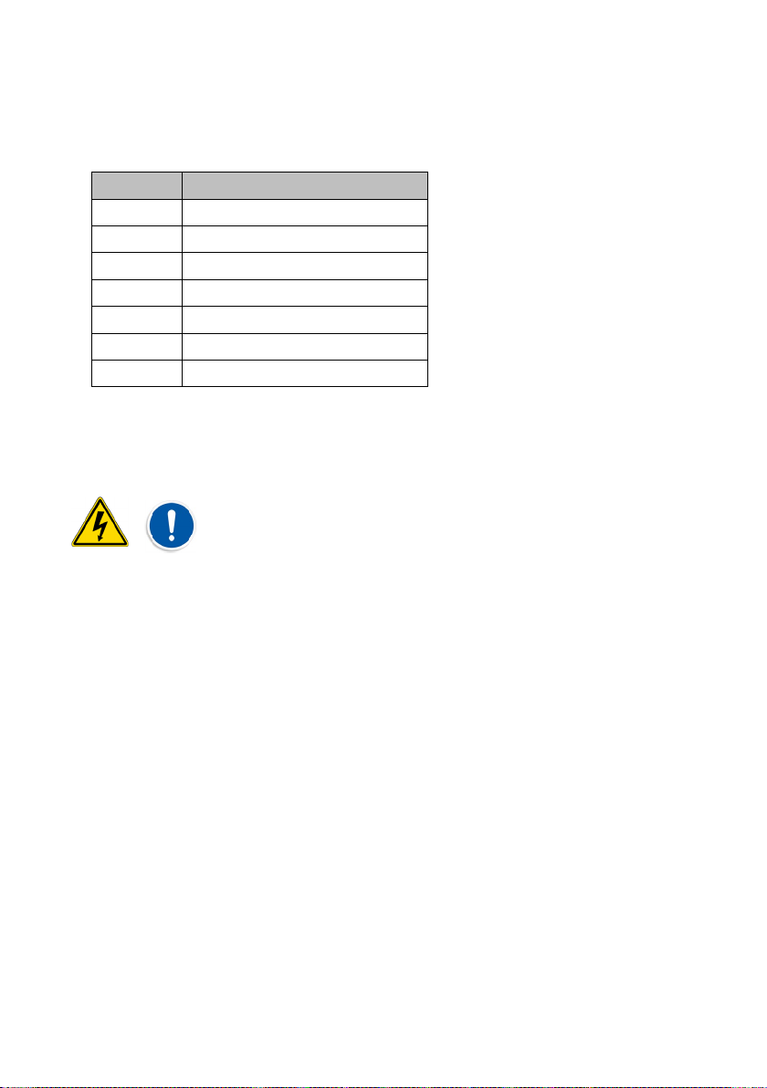
Table 4: Fuse specifications by model:
Model
FH1, FH2
RW 312U
5A 250V ceramic slow blow
RW 324U
5A 250V ceramic slow blow
RW 348U
5A 250V ceramic slow blow
RW 512U
10A 250V ceramic slow blow
RW 517U
10A 250V ceramic slow blow
RW 624U
10A 250V ceramic slow blow
RW 748U
10A 250V ceramic slow blow
6SETTING CHANGES
All setting changes must be carried out by suitably qualified
personnel.
The rectifier is supplied from the factory with default parameters for normal operation.
These settings are detailed below.
To adjust the settings:
1. Appropriate test equipment is necessary (depending on the adjustment), a
variable load, a variable DC power supply, an accurate voltage and current
meter are required.
2. The rectifier should be unscrewed from its mounting.
3. The rectifier must be disconnected from the battery and load.
NOTE:The trimpots to adjust the settings are accessible on the rear side of the rectifier.
Refer to Figure 8: Trimpot Functions for the trimpot descriptions.


Enatel DC System Manual
Page 20 of 26
Model: RWxxx
Version: 3.6
6.1 Default Settings
Table 5: Default Settings
Item
RW312U
RW324U
RW348U
RW512U
RW517U
RW624U
RW748U
Boost Voltage 14.2V 28.8V 57V 14.2V 17V 28.8V 57V
Float Voltage
13.7V 27.4V 54V 13.7V 17.4V 27.4V 54V
Boost to Float
Current
2A 1A 0.5A 3A 3A 2A 1A
Over Voltage
Shutdown
16V 32V 60V 16V 18V 32V 60V
Temp Comp 25°C 13.7V 27.4V 54V 13.7V 17.4V 27.4V 54V
Temp Comp 5°C 14.16V 28.32V 55.9V 14.16V 17.61 28.32V 55.9V
LVD On Voltage 12V 24V 48V 12V 12V 24V 48V
LVD Off Voltage 10V 20V 40V 10V 10V 20V 40V
Current Limit 20A 10A 6A 35A 26A 20A 12A
6.2 Adjust Float Voltage
Connect a variable load (set to minimum load) to the battery connections of the rectifier.
Disconnect the Temperature Compensation Probe. Connect an accurate voltmeter across
the load. Turn the mains on to the rectifier. Wait approximately 10 seconds for the rectifier
to switch back to Float Charge mode. Check that the rectifier is in Float Charge mode (as
indicated on the LEDs).
Adjust the Float Voltage trimpot to set the required float voltage.
6.3 Adjust Boost Voltage
Connect a variable load (set to minimum load) to the battery connections of the rectifier.
Disconnect the Temperature Compensation Probe. Connect an accurate voltmeter across
the load. Turn the mains on to the rectifier and adjust the load until the rectifier goes into
Boost Charge mode (as indicated on the LEDs).
Note that there is a 10 second delay when switching from Boost Charge mode to Float
Charge mode, but no delay when switching from Float to Boost.
Adjust the Boost Voltage trimpot to set the required boost voltage.
6.4 Adjust Boost to Float Current Threshold
Connect a variable load (set to minimum load) to the battery connections of the rectifier.
Disconnect the Temperature Compensation Probe. Connect an accurate current meter in
series with the load. Turn the mains on to the rectifier, wait 10 seconds and then adjust
This manual suits for next models
6
Table of contents
Other Enatel Power Supply manuals


Popular Power Supply manuals by other brands

Videx
Videx 520MR Installation instruction

Poppstar
Poppstar 1008821 Instructions for use

TDK-Lambda
TDK-Lambda LZS-A1000-3 Installation, operation and maintenance manual

TDK-Lambda
TDK-Lambda 500A instruction manual

Calira
Calira EVS 17/07-DS/IU operating instructions

Monacor
Monacor PS-12CCD instruction manual


