Users’ Manual Vibrating wire strain gage – embedment type
Page | 3
2 VIBRATING WIRE STRAIN GAGE
2.1 Operating principle
The vibrating wire strain gage basically consists of a magnetic, high tensile strength stretched wire, one
end of which is anchored and the other end is displaced proportionally to the variation in strain. The
stretched wire is thermally aged to minimize long-term drift and changes in calibration.
The strain gage works on the principle that if a coil/magnet assembly plucks a fixed length stretched
magnetic wire; its frequency of vibration is proportional to the tension in the wire. Any change in strain,
directly affects the tension in the wire, resulting in a corresponding change in its frequency of vibration. The
strain is proportional to the square of the frequency that can be measured and displayed directly in µ strain
by Encardio-rite’s EDI-54V vibrating wire indicator.
The wire is plucked by a coil magnet. Proportionate to the tension, the wire resonates at a frequency ‘f’,
which can be determined as follows:
f = [σg/ρ]1/2/ 2l Hz
Where: σ= tension of wire in kg/cm2
g = 980 cm/sec2
ρ= density of wire in kg/cm3
l = length of wire in cm
The relationship between stress, strain and the modulus of elasticity can be expressed as σ/ε = E. The
length of the wire in the strain gage is 15 cm, the centre distance between the annular end blocks is 14.9
cm and E = 2.11 x 10⁶ kg/cm2. Consequently the formula can be reduced to:
ε15 = 4.051 x 10⁻³ f2 µstrain
To summarize, any variation in strain causes the strain gage to deflect. This changes the tension in the
wire thus affecting the frequency of vibration of the wire when it is vibrating at its natural frequency. The
strain is proportional to the square of the frequency and the read out unit is able to display this directly in
µstrain.
NOTE: The value 4.051 x 10⁻³ µstrain/Hz2 is known as the effective gage factor of the strain gage. It
varies within limits from batch to batch. For the correct “effective gage factor” of the strain
gages supplied to you, please refer to the batch test report provided.
The modulus of elasticity of the strain gage is very low and the magnetic strain gage plucking wire in it
precisely follows the deflection of the concrete structure (or the steel section or rock surface) on which the
strain gage is mounted. It is not affected by the material or the coefficient of thermal expansion of the strain
gage element or its body.
NOTE: The coefficient of thermal expansion of the magnetic plucking wire used in all Encardio-rite
vibrating wire sensors is 11.0 ppm per oC.
2.2 General description
A strain gage is used where a load cell cannot be conveniently interposed to measure stress in a structure
for reason of geometry, capacity or economy and where load and stress can be worked out with reasonable
accuracy from knowledge of the relationship between stress and strain (modulus of elasticity). In such a
case, it is very convenient to have a strain gage, which can be embedded in the concrete structure.
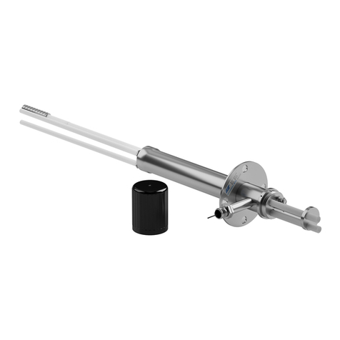
The Encardio-rite vibrating wire strain gage basically consists of a high tensile strength wire made out of a
magnetic material stretched between two stainless steel cylindrical end blocks. The wire is sealed in a
stainless steel tube by a set of double "O" rings fixed on each end block. This to a great extent ensures
resistance to corrosive, humid, wet and other hostile environmental conditions. Further protection is
