ENCARDIO RITE EAN-26 User manual

ONE STOP MONITORING SOLUTIONS | HYDROLOGY | GEOTECHNICAL | STRUCTURAL | GEODETIC
Over 50 years of excellence through ingenuity
USERS’ MANUAL
ENCARDIO-RITE ELECTRONICS PVT. LTD.
A-7, Industrial Estate, Talkatora Road Lucknow, UP - 226011, India | P: +91 522 2661039-42 | Email: geotech@encardio.com | www.encardio.com
International: UAE | Qatar | Bahrain | Bhutan | Europe | USA
India: Lucknow | Delhi | Kolkata | Mumbai | Chennai | Bangalore | Hyderabad | J&K
Doc. # WI 6002.103 R02 | Nov 2018
DIGITAL INCLINOMETER
OPERATION
MODEL EAN-26

Users’ Manual EAN-26 Digital inclinometer operation
www.encardio.com
Contents
1INTRODUCTION 2
2OPERATING PRINCIPLE 3
2.1 Inclination measurement 3
2.2 Digital Inclinometer cable and reel 3
2.3 Digital inclinometer probes 4
3PREPARING TO LOG A BOREHOLE 5
4READOUT UNIT 6
4.1 Using the readout unit 6
4.1.1 Establishing Bluetooth connection 6
4.1.2 Running inclinometer application on phone 6
4.1.3 Main menu 7
4.1.4 Connecting a digital inclinometer 7
4.1.5 System information 8
4.1.6 Creating a site 9
4.1.7 Creating a borehole 10
4.1.8 Default site and default borehole 10
4.1.9 Editing borehole parameters 10
4.1.10 Taking readings 11
4.1.11 Saving borehole log 14
4.2 Viewing data 15
4.3 Viewing data in table 15
4.3.1 Viewing data on graph 16
4.4 Borehole files storage 17
4.5 Borehole log database manager 17
4.5.1 Selecting multiple log files 18
4.5.2 Deleting borehole log 19
4.5.3 Creating files from borehole database 19
4.6 Setting database deletion password 20
4.6.1 Change password 20
4.6.2 Forgot password 20
4.7 Uploading files 21
4.7.1 URL settings 21
4.7.2 Uploading multiple files to server 21
4.8 Help menu 22
5CALCULATING DATA 23
5.1 Face error 23
5.2 Mean displacement 23
5.3 Absolute displacement 23
5.4 Deviation displacement 23
6FILE FORMATS 24
6.1 Digital inclinometer standard data format (*.CSV) 24
6.2 Digital inclinometer extended data format (*.CSV) 24
6.3 Digital inclinometer webview data format (*.DI1) 25
7INCLINOMETER DATA BACKUP 26
7.1 Connecting Phone to the PC 26

Users’ Manual EAN-26 Digital inclinometer operation
www.encardio.com
7.2Backing up the inclinometer database 26
7.3 Backing up the borehole logs 27
8RESTORING INCLINOMETER DATA 29
8.1 Restoring the inclinometer database 29
8.2 Restoring borehole logs 29
9TROUBLESHOOTING 31
9.1 Unable to connect Bluetooth 31
9.2Unable to connect to the probe 31
9.3 Files not uploading on FTP server 31
9.4 Inserting new SD card 31

Users’ Manual EAN-26 Digital inclinometer operation
Page | 1
Battery charging and care of rechargeable battery
CAUTION !
Always maintain cable reel’s battery in charged condition. Failure to do so will cause premature battery
failure. A battery which gets damaged due to non-compliance with the instructions given below is not
covered by our standard warranty and is also not eligible for free servicing.
Cable reel’s battery
The EAN-26 Digital Inclinometer Reel uses a removable sealed rechargeable Li-ion maintenance free
battery as a power source. A separate battery charger unit operating from universal AC mains supply is
supplied with each Inclinometer system. This battery charger operates from 90 to 260 V AC, 50 or 60 Hz
which makes it suitable for operation from AC mains available throughout the world.
A fully discharged battery needs 4 hours of charge to get fully charged. A partially discharged battery will
require proportionately less time but the time is difficult to calculate. As soon as the battery is fully charged
the charging current gets automatically reduced to a safe value.
On receiving the Inclinometer system for the first time recharge the battery for 4 hours using the supplied
mains powered battery charger.
If the DI Reel is not going to be used for more than 30 days, fully charge the battery before storing the DI
Reel. Also fully charge the battery before use if the DI Reel has not been used for more than 30 days.
If the data logger is not going to be used for more than 30 days, recharge the battery at least once every
30 days or so.
When battery voltage is showing 7.3V in system information screen (at Readout unit) it means
approximately 10 percent of battery capacity is left. Fully recharge the battery at the first opportunity.
Turn off mains AC supply to the charger before connecting to or disconnecting battery from the battery
charger. A fully charged battery will not get damaged but the battery life gets reduced if a fully charged
battery is kept connected to the charger for very long duration. It is recommended that the charger be
disconnected after 4 hours charging period is over.
The rechargeable battery needs replacement every 3 to 5 years (irrespective of hours of use). Replace
battery with Camcorder Battery BP522 or an equivalent from another manufacturer.
Phone’s (readout unit) battery
The EAN-26DI Readout unit uses an internal sealed rechargeable Li-ion maintenance free battery as a
power source. A separate battery charger/adaptor unit operating from universal AC mains supply is
supplied with each DI Readout unit. This battery charger operates from 90 to 260 V AC, 50 or 60 Hz which
makes it suitable for operation from AC mains available throughout the world.
On receiving the Readout unit for the first time discharge the battery fully and then recharge the battery for
2 hours using the supplied mains powered battery charger.
If the DI Readout unit is not going to be used for more than 30 days, fully charge the battery and switch
OFF the phone before storing the DI Readout unit. Also fully charge the battery before use if the DI Readout
unit has not been used for more than 30 days.

Users’ Manual EAN-26 Digital inclinometer operation
Page | 2
1 INTRODUCTION
The Digital Inclinometer uses an Android OS based mobile phone with a Bluetooth wireless interface as a
readout device. The recommended phone types have a large 800 x 480 pixel colour display with capacitive
touch screen that makes it easy to read the display while logging bore holes using Encardio-rite’s range of
traversing type vertical and horizontal borehole inclinometers.
EAN-26 Readout unit can be used to log bore hole profiles of boreholes up to 300 m deep in 0.5 / 1.0
meters increment or up to 999 feet deep in 2.0/4.0 feet increment using either biaxial or uniaxial
inclinometers.
The readout unit can store readings from up to more than 1000 bore holes. The readings are not lost even
if the power is turned off. Four readings are required for a biaxial inclinometer survey for each depth level
in a bore hole. In case of any error during logging the probe can be lowered back to the problem depth and
logging continued without having to start a fresh thus saving time.
A quick probe check mode allows verifying probe operation or calibration without having to configure a
dummy borehole log as is required by most other commercially available inclinometer data loggers.
The stored readings can be uploaded to a remote FTP server using GPRS/3G cellular network. The
uploaded data is in a format that allows the data to be easily imported in third party inclinometer data
presentation software like GTiltor a spread sheet program like Microsoft Excel.
Since readout unit is a mobile phone, most of the people are familiar with its operation. Working with a
mobile phone readout unit is very easy and user friendly.
(TRADEMARKS): GTilt is a trademark of Mitre Software Corporation, Canada; Microsoft Excel is a
trademark of Microsoft Corporation, USA.

Users’ Manual EAN-26 Digital inclinometer operation
Page | 3
2 OPERATING PRINCIPLE
2.1 Inclination measurement
The inclinometer probes employ an accelerometer to measure the tilt angle from the true vertical line or
horizontal plane with respect to the earth’s surface.
The accelerometer itself measures the change in acceleration due to gravity felt by it as it rotates about a
horizontal axis. It experiences maximum acceleration when its sensitive axis is truly vertical and minimum
acceleration when is sensitive axis is truly horizontal. In a vertical inclinometer probe the internal
accelerometer is mounted such that when the inclinometer probe is truly vertical, the accelerometer
sensitive axis is aligned vertically. In a horizontal inclinometer probe the accelerometer sensitive axis is
aligned vertically when the probe is aligned along a true horizontal plane.
As the accelerometer rotates about a horizontal axis along a vertical plane its output changes proportionally
to the sine of the angle its sensitive axis makes from the true vertical. So an inclinometer’s output is
generally proportional to the sine of the angle of tilt (or inclination) rather than the tilt angle of the
inclinometer probe itself.
However, this sine law variation of an inclinometer probe output is more useful to us as the subsequent
calculations to determine the ground profile uses the sine of the tilt angle rather than the tilt angle itself.
An uniaxial vertical inclinometer probe can measure the tilt along a vertical plane passing through the probe
axis. A biaxial inclinometer probe can measure the tilt independently along two vertical planes, that are
orthogonal to each other, with their intersection line coincident with the inclinometer probe axis.
A horizontal inclinometer probe is generally used to measure tilt along a vertical plane passing along the
axis of the inclinometer. A second accelerometer is often provided to measure the tilt along a plane
perpendicular to the horizontal inclinometer probe axis so that any rotation of the horizontal probe during
a traverse can be detected and correction for this applied.
2.2 Digital Inclinometer cable and reel
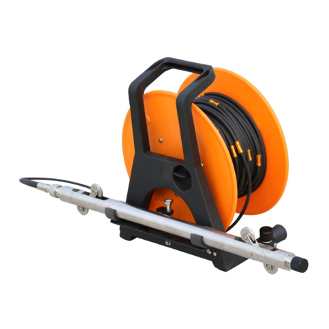
The EAN-26 Readout unit is meant for use with
EAN-26R cable reel. Reel interfaces with digital
output uniaxial or biaxial digital inclinometer
probes over a long cable.
EAN-26R cable reel is having a Bluetooth
interface unit inside the reel and a long cable to
interface with digital inclinometer probe. EAN-26R
cable reel is powered with 7.2 V compact size
rechargeable battery. Battery is accessible from
outside. Battery can be removed for charging by
opening battery holder. Power ON/OFF
pushbutton is provided on reel’s disk near battery
holder.
EAN-26R cable reel uses two core cable to
interface with digital inclinometer probe. The cable length varies depending on ordered option. Ferrules
are crimped on cable at defined intervals to suspend the probe in borehole.
Cable reels are supplied with ordered length of cable marked at constant distances with ferrules in either
metric or imperial units of measurement.
Figure 3.1

Users’ Manual EAN-26 Digital inclinometer operation
Page | 4
Cable in meters are having golden ferrule crimped at 0.5 meters interval while red ferrules are crimped at
1.0 meters interval. White ferrules are crimped at every 5.0 meters interval and are marked with the depth
value.
Cable in feet are having golden ferrule crimped at 2.0 feet interval while red ferrules are crimped at 4.0 feet
interval. White ferrules are crimped at every 20 feet interval and are marked with the depth value.
2.3 Digital inclinometer probes
The model EAN-26MV digital tilt sensing inclinometer probe is meant for use with
EAN-26R cable reel. Reel interfaces with digital output biaxial inclinometer probes
(often called torpedo by other manufacturers). These types of probes are known as
digital output inclinometer probes in which the output is in the form of a series of
pulses.
Inclinometer probes from Encardio-rite and most other manufacturers use
accelerometers as the basic tilt sensor. In addition some kind of signal conditioning
is also carried out to boost the signal voltage and then doing analog to digital
conversion to make it suitable for noise free transmission over long cables.
EAN-26R cable reel is designed for use with probes that require an excitation voltage
of +12 to +30 V. However, the EAN-26R cable reel is designed for use with variety
of digital inclinometer probes from Encardio-rite. The probe calibration is
independent of the Reel configuration.
The EAN-26MV digital Inclinometer probe uses two MEMS sensors that are
mounted orthogonally inside the probe. They measure the tilt of the probe along a
plane passing through the two wheel arms and the other in a plane perpendicular to
the first. As measurement of inclination in two orthogonal direction is simultaneously
available the probes are known as bi-axial probe.
The traditionally available analog probe which gave a voltage output proportional to
the sine of the angle of tilt of the probe along any of the two axes. The EAN-26 digital
probe however gives the output in digital form (in a numeric form). The output value
is the distance between the two wheels multiplied by the sine of the angle of tilt in
that plane. So essentially the output of the probe is the horizontal displacement of
the top wheel arm centre from an axis passing through the centre of the bottom
wheel arm assembly along the plane of rotation or tilt.
Inclinometer probes have a significant current consumption and thus introduce a
drop in excitation voltage across the connecting cable. The EAN-26 cable reel
supplies an excitation voltage of +29 V. The longest cable that can be connected
between the data logger and the inclinometer probe is that which will not cause the excitation voltage to
drop to less than +12 V at the inclinometer probe terminals.
Figure 3.2

Users’ Manual EAN-26 Digital inclinometer operation
Page | 5
3 PREPARING TO LOG A BOREHOLE
Site and borehole names must be created in readout unit before logging a borehole. Edit borehole
parameters be providing required information. Then the inclinometer probe is lowered in the borehole down
to the deepest level to be logged and gradually pulled up in 0.5 or 1.0 m (2 or 4 feet) intervals and readings
stored. The interval by which the probe is raised after each reading is known as the depth interval. For the
first run the face A+ of the inclinometer is kept pointing towards the reference groove of the inclinometer
casing in the borehole. The reference groove is one of the four grooves in an inclinometer casing that has
been chosen to be the reference groove. After the first run is over the inclinometer probe is taken out of
the casing and rotated 180 degrees and reinserted in the inclinometer casing. Conventionally this traverse
is known as A- face. For a biaxial probe the second axis is labeled as B+ during the first traverse and B-
during the second traverse.
Borehole files (logs) uses face conventions as face A+ is referred as face A, face A- is referred as face B,
face B+ is referred as face C and face B- is referred as face D.
For Encardio rite vertical inclinometer probes the side with the topmost wheel is labeled as face A+. When
the inclinometer probe tilts towards the topmost wheel, i.e. towards face A+, the output of A axis increases
in the positive direction. If the tilt is in reverse direction the sign of the output voltage is negative.

Users’ Manual EAN-26 Digital inclinometer operation
Page | 6
4 READOUT UNIT
The Digital Inclinometer system is using Mobile Phone as a Readout
unit. Phone is running on Android operating system for providing
powerful platform to manage applications efficiently. It has so many
features like phone calls, SMS, MMS, GPRS/3G, Wi-Fi, Bluetooth,
USB and high resolution Camera. User can use it as mobile phone
for making calls. It has GPRS/3G which enables user to access
internet from site to upload/download files and checking E-mails.
Wireless Bluetooth can be used to send files to PC or any other
Bluetooth device. High resolution camera can be helpful to take site
conditions photographs and send them to the back office by sending
MMS. It has higher capacity external memory card of 8GB which can
store lots of data. Data backup can be taken on regular basis by
connecting phone with PC through USB cable.
4.1 Using the readout unit
The inclinometer software running on phone can take borehole readings and store them into memory.
Inclinometer software has ability to show borehole logs in tabular format and create plots of borehole data
instantly after borehole reading is complete. Borehole data files are created automatically while saving
borehole log. These files can be recreated from software database when needed. Borehole files can be
uploaded to remote server through GPRS/3G/Wi-Fi.
4.1.1 Establishing Bluetooth connection
Inclinometer system is using Bluetooth connection for communicating Phone with Reel. Connect the probe
with Reel. Turn ON the Reel by pressing push button provided on Reel’s disk near battery holder. Once
push button is pressed Reel becomes ON. The indicator will glow in bright RED colour to ensure that reel
is ON. Now power ON the Phone and go to settings and then Bluetooth settings. Turn ON the Bluetooth
and click on “scan” button showing on phone’s screen. Phone will show the list of Bluetooth devices found.
Find the Reel’s serial number on phone screen and click for pairing the phone with Reel. Once pairing
button is pressed it will ask to enter passkey for authentication. Enter pairing code “6965785054” and then
press OK. On successful authentication it will show that device is paired. Now Phone is paired with Reel.
This activity is required for first time connection with Reel.
4.1.2 Running inclinometer application on phone
Running Inclinometer application is very simple. It is as simple as playing games
in mobile phone. The graphic user interface makes it users friendly and thus easy
to operate. Go to applications and then click on Digital Inclinometer application icon
as shown in figure 5.2. Once DI application is clicked to run, it will show the name
of the application and its version (see figure 5.3). This screen will splash for few
seconds and then option menu appears. Figure 5.4 shows the option menu where
we can change password for database deletion or regenerate deletion password.
We can see help information by pressing help button or we can go to main menu
to proceed further.
Figure 5.1
Figure 5.2

Users’ Manual EAN-26 Digital inclinometer operation
Page | 7
4.1.3 Main menu
Main menu is the place where we can do many functions. Figure 5.5 shows the main menu items. We can
make connection with a reel over Bluetooth using connection button. System information can be seen by
pressing system info button. It will show the information about reel, probe, Bluetooth and phone. New site
and borehole can be created using create borehole button. Borehole parameters can be modified using
edit borehole option. Borehole readings can be taken by pressing take reading button.
Borehole data can be viewed in tabular form or can be plotted on graph using view data option. Borehole
files can be uploaded to a remote server using upload files button. Borehole logged database can be
managed using database manager option. Site list shows the list of total sites created in this readout unit.
Borehole list is showing the list of boreholes created under a site name which is selected in site list.
Borehole information shows the borehole information of selected borehole from borehole list.
4.1.4 Connecting a digital inclinometer
Once the reel is turned ON and phone is paired with reel, we can connect phone with reel using connection
button from main menu. Go to main menu and press connection button. It will show a list of paired Digital
inclinometers as shown in figure 5.6. List is showing the serial numbers and Bluetooth addresses of the
Figure 5.4
Figure 5.3
Figure 5.5

Users’ Manual EAN-26 Digital inclinometer operation
Page | 8
reels. Click on desired reel to connect. Once clicked on a reel, it will try to connect and a message window
will appear to acknowledge that phone is connecting to the reel. Figure 5.7 is showing an example of
Bluetooth connection screen. Phone gets connected to the reel after few seconds.
Bluetooth connection status can be seen on top right corner of the screen as shown in figure 5.8. Now we
can check system information to see reel, probe, Bluetooth and phone information.
4.1.5 System information
System information can be seen by pressing system info button from
main menu. It shows the information about reel, probe, Bluetooth
and phone. On pressing system info button from main menu, it will
show the inclinometer screen. We can choose to see other screens
by clicking navigation tabs.
4.1.5.1 Inclinometer information
Inclinometer screen shows the information about reel and the probe.
Figure 5.9 is showing an example of inclinometer screen of a reel. It
is showing the Reel’s battery voltage, serial number, model number,
firmware version of reel’s processor, reel’s connection time and
connectivity. It shows the probe’s serial number, model number,
firmware version of probe’s processor, probe’s connection time and
connectivity. Battery voltage can be useful for reel’s health
monitoring. It is recommended to get battery full charged before
going to the site.
4.1.5.2 Calibration information
Calibration screen shows the calibration information of the probe.
Figure 5.10 shows the calibration screen of a probe. It shows the Probe type vertical or horizontal, sensor
type, probe measurement units, probe length, probe calibration date, calibration factor for axis-A,
calibration factor for axis-B, offset value for axis-A and offset value for axis-B. These information is useful
for data verification.
Figure 5.6
Figure 5.7
Figure 5.8
Figure 5.9

Users’ Manual EAN-26 Digital inclinometer operation
Page | 9
4.1.5.3 Bluetooth information
Bluetooth screen shows the Bluetooth connection information. Figure 5.11 shows the Bluetooth screen of
a reel. It shows the Reel’s serial number, Bluetooth address and connectivity.
4.1.5.4 Phone information
Phone screen shows the phone information as shown in figure 5.12. It shows phone’s IMEI number and
the network service provider.
4.1.6 Creating a site
Site and Borehole menu can be opened on pressing create site button from main menu. Figure 5.13 shows
the site and borehole menu. On pressing create button under site list, it will open site creation menu as
shown in figure 5.14. Enter site code in edit box under site name. Site code cannot be of more than 7
letters. Enter site description in edit box. Site details can be written here. Press on save button to create
this site. Site and its description can be seen under site list in site and borehole menu (figure 5.13). Any
site can be deleted by selecting a site name from site list and then press on delete button.
Figure 5.10
Figure 5.11
Figure 5.12

Users’ Manual EAN-26 Digital inclinometer operation
Page | 10
4.1.7 Creating a borehole
Open Site and Borehole menu on pressing create site button from main menu. Select site name under
which new borehole is to be created. On pressing create button under borehole list, it will open borehole
creation menu as shown in figure 5.15. Enter Borehole code in edit box under site name. Borehole code
cannot be of more than 7 letters. Default settings for this borehole can be imported from previously created
boreholes. Press on change button to reset default borehole to import settings. On pressing change button,
it will open default borehole selection menu. Choose desired borehole to import parameters from. Figure
5.16 is showing an example of default borehole selection menu. Any borehole can be deleted by selecting
a borehole name from borehole list (figure 5.13) and then presss on delete button.
4.1.8 Default site and default borehole
No borehole can be created under default site. Default site and Default borehole cannot be deleted. Default
site and default borehole are given only for reference. Default Borehole readings can’t be stored in
database while borehole readings can be taken.
4.1.9 Editing borehole parameters
Borehole parameter can be edited using edit borehole option. Select site and borehole from main menu
and then press on Edit borehole to edit parameters of selected borehole.
Figure 5.13
Figure 5.14
Figure 5.15
Figure 5.16

Users’ Manual EAN-26 Digital inclinometer operation
Page | 11
Figure 5.17 is showing an example of edit borehole menu option. Site and borehole names are showing
on top of the screen. Select probe unit in meters or feet from drop down menu under units. Set depth of
the borehole and select reading interval using drop down menu.
It is recommended to enter interval equal to the length of the probe. Enter operator name and borehole
comments in edit box provided under operator and comments heading. File name prefix for borehole log
is showing under file name prefix heading. Press OK to save borehole settings.
Pressing on cancel button will exit from this menu and borehole settings will not be updated. Borehole
comments can be seen under site list in site and borehole menu (figure 5.13).
4.1.10 Taking readings
Once the site and borehole are selected from main menu (figure 5.5) and phone is connected with reel,
readings can be started by pressing take reading button from main menu. Pressing on take reading button
from main menu, it will open reading screen as shown in figure 5.18.
Lower the probe into borehole at depth showing on phone’s screen. Axis-A and Axis-B displacement values
are showing in meters/feet. Noise bar showing right side of the screen represents the present noise level
in the readings received from probe. Present noise level in terms of micro volts is showing the noise
contents in electrical signal at probe. Noise bar limit is showing in terms of displacement unit on top of the
noise bar to correlate the noise level in terms of displacement units. Noise bar limit represents the 100%
noise level in the noise bar. Red arrow above noise bar showing in figure 5.18 indicates that noise level is
exceeding the noise bar limit. Solid green circle near stable in figure 5.18 represents that present reading
is stable while red circle near stable in figure 5.19 represents that present reading is not stable. Noise
window must be set from advanced menu to check readings are stable or not. It is recommended to accept
readings only when readings are stable.
Figure 5.17
Figure 5.18

Users’ Manual EAN-26 Digital inclinometer operation
Page | 12
Readings showing on screen are calculated by taking average of displacement readings. Number of
readings for averaging is showing on top left side of the screen. It can be set from option menu. It is good
to take average of large number of readings but run-time become slower. Borehole data log are taken in
two sets. First set of readings are taken when probe direction is normal while second set of readings are
taken when probe direction is rotated to 180 degree or we can say probe direction is reversed. Probe
direction is showing on top centre of the screen. UP and DN buttons near depth are used to go up or go
down the probe position into the borehole. This button is useful in EDIT mode.
Let us take an example to understand how to take readings. Borehole depth is set to 10.0 meters and
interval is 0.5 meters in this example. Lower the probe into borehole at depth showing on phone’s screen
(depth is 10.0 meters for this example) and wait until noise level in noise bar becomes low. Press Accept
button (when readings are stable) to save reading for the depth showing (10.0 meters) on screen. Once
accept button is pressed it will save the reading and the depth and moved to next interval (9.5 meters in
this case). Pull the probe and fix it at 9.5 meters marking. Wait until readings are stable and then press
accept button to store readings for 9.5 meters. Repeat the process again and again to take readings for
each interval until top of the hole is reached. On accepting reading for 0.0 depths, first set of reading gets
completed and a message will appear on screen to reverse the probe and repeat the readings again. Press
OK button to proceed further.
Probe direction showing on top of the screen will now show ‘Reverse’. Rotate the probe direction to 180
degree and lower the probe again into borehole at depth (10.0 meters) showing on the screen. Small digits
in yellow colour below axis-A and axis-B readings are showing run time face error. Figure 5.20 is showing
an example of reading screen. Face error is the difference in reading from normal to reverse probe direction
for same interval. Face error should be zero in ideal case. It should be approximately same for a probe at
each interval. Wrong readings can be identified with the help of face error. Progress bar showing right-
bottom on screen indicating that probe is connected. Stored borehole logs can be viewed any time by
pressing view data button to compare readings.
Figure 5.19

Users’ Manual EAN-26 Digital inclinometer operation
Page | 13
4.1.10.1 EDIT readings
Readings can be verified or retaken using EDIT mode. Pressing Down button once enters application in
EDIT mode. Once DN button is pressed, Accept button becomes Edit button and small digits in green
colour below axis-A and axis-B will appear for showing stored log for the interval showing on screen. Lower
the probe into borehole and press DN button corresponding to probe position into borehole. Monitor stored
log and present log to verify the reading log. If any stored log found wrong, new reading can be stored by
pressing EDIT button. UP and DN button can be used to reach the desired probe position. Verify all
readings at different intervals up to which readings are doubtful. Application automatically exits from EDIT
mode when highest logged interval is reached. This feature saves lots of time and efforts.
4.1.10.2 Reading option settings
Pressing option button from readings screen (figure 5.20) opens options screen. Figure 5.21 shows the
reading options screen. Number of readings for averaging data for axis-A/B can be set using UP/DN
arrows. Taking average for displacement can be disabled by un-checking the tick box. Borehole log file
name contains pre-fix as site code and borehole code while suffix having reading start date and time stamp.
Comments can be entered for borehole log file. Advanced options menu can be opened by pressing
advanced button.
Figure 5.20

Users’ Manual EAN-26 Digital inclinometer operation
Page | 14
4.1.10.3 Advanced options
Figure 5.22 shows advanced options menu. Single set of readings can be set by checking the tick box.
Beep on accept reading can be enabled/disabled by checking/un-checking the corresponding tick box.
Similarly vibration on accept readings can be enabled/disabled by checking/un-checking the corresponding
tick box.
Stable window is showing the noise window for detection of stable readings. It is the window of standard
deviation for readings received from probe. Set noise limit can be seen in terms measurement units. Stable
window can be adjusted depending on how noisy the readings are in the field. It is recommended to keep
stable window minimum.
4.1.11 Saving borehole log
Once borehole readings are taken at each interval and probe reached at 0.0 (top of the hole), after
accepting last reading application will show reading complete message. Press OK to complete the reading
process. On pressing OK button application opens save file formats screen as shown in figure 5.23.
Standard or extended file format can be selected for generating CSV file. Additional file can be generated
in web view data format (DI1) for analyzing data at server. Refer section § 7 for more details about file
Figure 5.21
Figure 5.22

Users’ Manual EAN-26 Digital inclinometer operation
Page | 15
formats. Operator name can be entered in text box. Pressing on save button will save reading log into
borehole database and files will be generated at external memory (SD card). Refer section § 10.3 for
viewing created borehole files.
4.2 Viewing data
Reading log can be viewed using view data option. Go to main menu (figure 5.5) and select site and
borehole for which borehole data to be viewed. Pressing view data button will open view data menu as
shown in figure 5.54. Borehole Base file can be set on pressing reset base file button. Figure 5.25 shows
reset base file menu. Choose a borehole file to set it base file and press OK. View data menu (figure 5.24)
will show a list of borehole logs which are taken later to base file. Select only those borehole logs for which
we want to see data. Borehole data can be viewed in tabular form by pressing view table button. Data can
be plotted on graph by pressing view graph button.
4.3 Viewing data in table
On pressing view table button from view data menu (figure 5.24) application will show data in tabular format.
Figure 5.26 showing an example of a borehole log in table form. Drop down list at top of the screen showing
list of borehole files. Since site/borehole are same for all files of this borehole so only file name suffix is
Figure 5.23
Figure 5.24
Figure 5.25

Users’ Manual EAN-26 Digital inclinometer operation
Page | 16
displayed in file list. B: before file name represents base file while S: represents selected file. Select a file
from drop down list to view its data.
Drop down list below file list is showing reading parameters list. Different data options can be selected from
this drop down list. These options are Raw data A, Raw data B, mean A/B, Face error A/B absolute A/B
and deviation A/B.
Measurement unit is showing at left bottom side on the screen. We can plot data on graph on pressing
view graph button. Use phone’s back key to exit from this menu.
4.3.1 Viewing data on graph
On pressing view graph button from view data menu (figure 5.24) application will plot data on a graph.
Figure 5.27 showing an example of a borehole data on a graph. Drop down list at bottom left of the screen
showing axis of measurement. Axis-A or Axis-B can be chosen with this drop down list. Borehole log file
name suffix is displayed under graph in various colours. File name colours are displaying corresponding
to their data on graph area.
Drop down list at right bottom of the screen is showing reading parameters option. Different data options
Figure 5.26
Figure 5.27

Users’ Manual EAN-26 Digital inclinometer operation
Page | 17
can be selected from this drop down list. These options are Mean, Face error Absolute and Deviation.
Axis of measurement is showing on top of the graph. X-axis represents borehole parameter while Y-axis
represents borehole depth. Buttons given near right bottom side on the screen can be used for
manipulating the zoom in, zoom out and pan. Since phone’s screen is a touch screen so user can scale
and move the graph using finger tips also.
4.4 Borehole files storage
Borehole files are stored at external memory (SD card). Open phone’s File manager and explore phone’s
external memory. Explore root directory and find folder Inclino Files at path /mnt/sdcard/.This folder will
be having two sub folders CSV files and Web view file.
Figure 5.28 showing contents of CSV files folder. It is having one archive folder and different CSV files.
These CSV files are borehole log files generated while saving borehole log after taking readings (refer
section § 5.1.11). Archive folder is used to keep uploaded files (refer section § 5.6).
Figure 5.29 showing contents of Web view files folder. It is having one archive folder and different DI1 files.
These DI1 files are borehole log files generated while saving borehole log after taking readings (refer
section § 5.1.11). Archive folder is used to keep uploaded files (refer section § 5.6).
4.5 Borehole log database manager
Borehole database can be managed using Database Manager. It can be opened by pressing database
manager button from main menu (figure 5.5). Figure 5.30 is showing an example of database manager
screen. Borehole logs are listed on centre of the screen. Borehole log list can be filtered using Filter list
button. Selected logs can be deleted using delete record button. Borehole files (CSV / DI1) can be re-
created using create files button. Once a log is clicked, its information will show under log information
heading irrespective of whether log is selected or not.
Figure 5.28
Figure 5.29
Table of contents
Other ENCARDIO RITE Measuring Instrument manuals

ENCARDIO RITE
ENCARDIO RITE ESM-40S User manual

ENCARDIO RITE
ENCARDIO RITE EAN-95MW User manual

ENCARDIO RITE
ENCARDIO RITE ESM-12S User manual

ENCARDIO RITE
ENCARDIO RITE EAN-26CCJ User manual

ENCARDIO RITE
ENCARDIO RITE EDI-53P/L/I User manual

ENCARDIO RITE
ENCARDIO RITE EDS-20V-E User manual

ENCARDIO RITE
ENCARDIO RITE EAN-26MH User manual

ENCARDIO RITE
ENCARDIO RITE EAN-90M User manual

ENCARDIO RITE
ENCARDIO RITE EDS-71V User manual