Elster Instromet RABO User manual

Instruction Manual
Rotary Gas Meters
Type RABO
Betriebsanleitung
Drehkolbengaszähler
Typ RABO
Mode d`emploi
Compteur de gaz à pistons rotatifs
Type RABO
Manual de instrucciones
Contador de gas de pistones rotativos
Modelos RABO
Instruzioni d`uso
Contatore gas a pistoni rotanti
Tipo RABO
Gebruiksaanwijzing
Rotorgasmeters
Type RABO
EnglishDeutschFrançaisEspañolItalianoNederlands


Instruction Manual
Rotary Gas Meters
Type RABO
RABO G16-G400
English


Elster-Instromet
5
73021678d © Elster GmbH • All rights reserved • Subject to technical modication
English
Contens
1. Staff .................................................................................................................. 6
2. Legal Declarations ............................................................................................ 6
3. Intended Use and Field of Application .............................................................. 6
4. Technical Data .................................................................................................. 8
5. Operating Location ........................................................................................... 9
6. Installation Position, Flow Direction .................................................................. 10
7. Installation / Connection ................................................................................... 10
8. Lubrication and Maintenance ............................................................................ 12
9. Commissioning ................................................................................................. 13
10. Decommissioning ............................................................................................. 13
11. Function Check ................................................................................................. 13
12. Pulse Generators ............................................................................................. 14
13. Pressure Test Point .......................................................................................... 15
14. Temperature Test Points .................................................................................... 15
15. Index Versions .................................................................................................. 16
16. Absolute ENCODER S1D ................................................................................ 17
17. Care and Cleaning ............................................................................................ 19
18. Recycling and Environmental Protection .......................................................... 19
19. Annex A (ATEX Approvals) ............................................................................... 20
20. Annex B (Plastics Used) ................................................................................... 21
21. Annex C (Declaration of Conformity) ............................................................... 22

Elster-Instromet
673021678d © Elster GmbH • All rights reserved • Subject to technical modication
1. Staff
These instructions are aimed at staff who have adequate specialist and technical
knowledge (in Germany, for instance, in accordance with DVGW Codes of Practice
492 and 495 or comparable technical regulations) on the basis of their training and
experience in the sector of energy and gas distribution.
This product is intended
for calibratable volumetric metering of
- ammable gases: natural gas/town gas/propane/ butane,
- non-ammable gases: air/nitrogen/inert gases,
- and is suitable for use in potentially explosive atmospheres of Category 2
(Zone 1) of Class EX II 2 G c IIC.
Other elds of application / media on request.
This product is not intended for
- metering of aggressive gases, e.g. biogases or sewage gases, oxygen,
acetylene, hydrogen.
2. Legal Declarations
- Declaration of Conformity – see Annex C
- Period of validity of calibration – this is based on the regulations of the country
concerned, in which the rotary gas meter will be used.
- The calibration of rotary gas meters is only valid for the period of validity of
calibration. Once this has elapsed, rotary gas meters may no longer be used for
purposes which are subject to obligatory calibration.
3. Intended Use and Field of Application

Elster-Instromet
7
73021678d © Elster GmbH • All rights reserved • Subject to technical modication
English
1 Meter housing 6 LF pulse generator
2 Housing cover (front) 7 HF pulse generator
3 Housing cover (rear) 8 Temperature test point
4 Pistons 9 Pressure test point
5 Index head
Please contact your Elster-Instromet Customer Service
(Tel. +49 (0)6134-605-0 / -346) for assistance in commissioning, maintenance
and installation of encoders, pulse generators and volume correctors for instance.

Elster-Instromet
873021678d © Elster GmbH • All rights reserved • Subject to technical modication
Elster-Instromet
73021678a © Elster GmbH · All rights reserved · Subject to technical modification 6
Type RABO
Size: G 16 to G 250
Nominal diameter: DN 32 to DN 100
Pressure ratings: PN 16 or CLASS 150
Temperature ranges:
- gas / ambient
- storage
-25 °C to +70 °C
-40 °C to +70 °C
Housing material: Aluminium or
Spheroidal graphite cast iron
Mechanical ambient conditions: M1
Pulse generators
LF pulse generator E1
(reed contact)
Wiegand pulse
generator
HF pulse generator
(acc. to EN 60947-5)
U= 24 V U 30 V Urated = 8 VDC
I= 50 mA I100 mA I 3 mA (exposed)
P= 0,25 VA P
600 mW I
1 mA (covered)
Ri = 100 (series resistor) Ri= 1 k
Absolute ENCODER S1D
Absolut ENCODER S1D
Index
Number of Indexes 2
Number of digit rollers per
index
8
Temperature ranges -25°C to +60°C
Safety class IP 67
Interfaces and
ATEX approval
NAMUR (II 2 G EEx ia IIC T4) or
SCR/SCR+ (II 2 G EEx ib IIB T4) or
M-BUS (without ATEX)
LF pulse generator optional or retrofittable INS-10, -11, -12
Ri = 100 (series resistor)
I
I
i
i
i
U= 24 V, I = 50 mA, P = 0,25 VA,
i i i
4. Technical Data
400
150

Elster-Instromet
9
73021678d © Elster GmbH • All rights reserved • Subject to technical modication
English
5. Operating Location
If you …
- wish to mix in odorisation agents or
- use solenoid valves,
please always t them only downstream of the meter. Otherwise, the device may be
damaged.
The ow through the meter must be free of vibrations / pulsations in order to avoid
measuring errors.
Compliance with the specied operating and ambient conditions as indicated on
the type label is absolutely essential for safe operation of the meter and additional
equipment.
The gas may not contain suspended particles > 50 µm. In addition, the gas must
be dry. Otherwise, the meter may be damaged.
To protect the meter, a cone strainer with mesh size 250 µm must be installed on all
new installations, and is also recommended for existing installations. When installing
the meter in a vertical position, with the direction of ow from bottom to top, a strainer
must be tted to both the meter inlet and outlet (to protect against falling dirt).
Elster-Instromet
10 73021678d © Elster GmbH • All rights reserved • Subject to technical modication
6. Installation Position, Flow Direction
Gas can be fed through the RABO rotary gas meter both horizontally and vertically. The
piston shafts and digit rollers on the index must always be aligned horizontally.
The index can be turned through up to 355° for optimum ease of reading in different
installation/operating positions.
Warning! Never clean the plastic hood of the index with a dry
cloth owing to the risk of explosion resulting from electrostatic
discharge! Please only ever use an adequately water - moistened
cloth!
Before installation please ensure:
- that the protective caps and/or plastic sheeting is or are removed,
- that the meter and accessories have been inspected for transport damage,
- that the pistons rotate easily in the measuring chamber
(e.g. by blowing on them),
- that the accessories have been checked for completeness
(e.g. plug connectors, oil for initial lling).
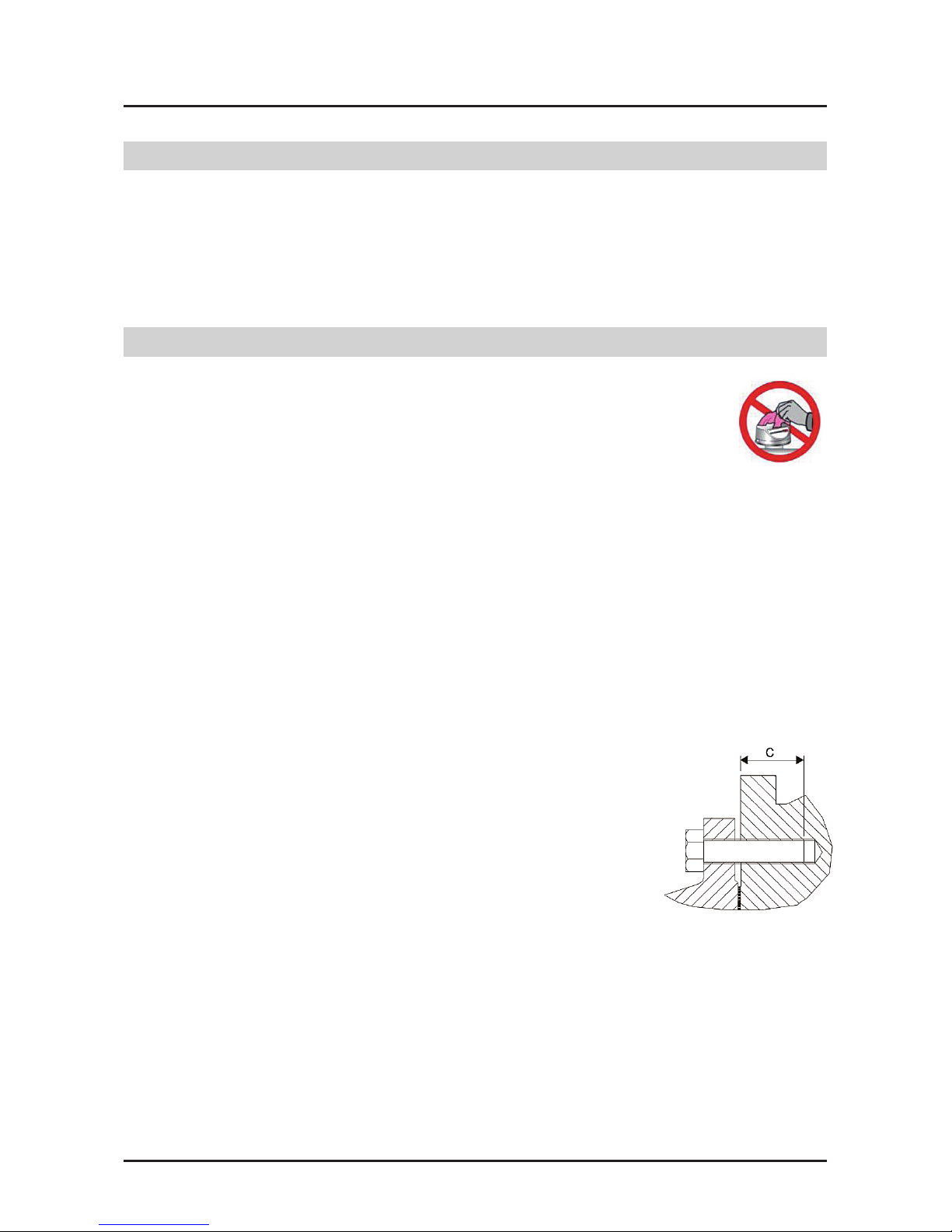
You will require the following items for installation:
- Suitable seals/gaskets for the relevant gases.
- For installing the meter in the pipe, use screws
in accordance with DIN 931. The screw length
must be selected so that a thread reach of
16 - 22 mm (M12 - M16) or 20 - 28 mm (M20)
into the meter is guaranteed. The recommended
tightening torque is dened in the table and must
not exceed 50 Nm for M12 and 100 Nm for M16
and M20.
7. Installation / Connection

Elster-Instromet
11
73021678d © Elster GmbH • All rights reserved • Subject to technical modication
English
Elster-Instromet
73021678a © Elster GmbH · All rights reserved · Subject to technical modification
9
DN Screw size Screws per meter
torque Nm
32 PN 10/16 M16 8 50
CLASS 150 M12 8 35
40 PN 10/16 M16 8 60
CLASS 150 M12 8 40
50 PN 10/16 M16 8 60
CLASS 150 M16 8 50
80 PN 10/16 M16 16 55
CLASS 150 M16 8 85
100 PN 10/16 M16 16 60
CLASS 150 M16 16 60
Then install the meter,
– gas-tight,
– with the supplied accessories,
– only in flow direction (as marked by an arrow on the meter housing or index
head S1D),
– only unstressed,
– the piston axes must be horizontal, check using a spirit level.
– when fitting the seals and gaskets, ensure that they are aligned
concentrically and do not project into the flow channel,
– weatherproof.
If you have specified the installation or operating position when ordering, all
attachments will have been fitted in accordance with the installation position
ex-works.
If you wish to install the unit vertically at a later point, you must turn the
index head and other attachments, e.g. volume corrector, through 90°.
We recommend that you contact our Elster-Instromet Customer Service
(Tel. +49 / (0)6134-605-0 / -346) for such conversion work.
Then install the meter,
- gas-tight,
- with the supplied accessories,
- only in ow direction (as marked by an arrow on the meter housing or index
head S1D),
- only unstressed,
- the piston axes must be horizontal, check using a spirit level.
- when tting the seals and gaskets, ensure that they are aligned concentrically
and do not project into the ow channel,
- weatherproof.
If you have specied the installation or operating position when ordering, all attachments
will have been tted in accordance with the installation position ex-works.
If you wish to install the unit vertically at a later point, you must turn the index head
and other attachments, e.g. volume corrector, through 90°.
We recommend that you contact our Elster-Instromet Customer Service
(Tel. +49 / (0)6134-605-0 / -346) for such conversion work.
Rec. tightening
torque Nm (Dry)
Elster-Instromet
73021678a © Elster GmbH · All rights reserved · Subject to technical modification
9
DN Screw size Screws per meter
torque Nm
32 PN 10/16 M16 8 50
CLASS 150 M12 8 35
40 PN 10/16 M16 8 60
CLASS 150 M12 8 40
50 PN 10/16 M16 8 60
CLASS 150 M16 8 50
80 PN 10/16 M16 16 55
CLASS 150 M16 8 85
100 PN 10/16 M16 16 60
CLASS 150 M16 16 60
Then install the meter,
– gas-tight,
– with the supplied accessories,
– only in flow direction (as marked by an arrow on the meter housing or index
head S1D),
– only unstressed,
– the piston axes must be horizontal, check using a spirit level.
– when fitting the seals and gaskets, ensure that they are aligned
concentrically and do not project into the flow channel,
– weatherproof.
If you have specified the installation or operating position when ordering, all
attachments will have been fitted in accordance with the installation position
ex-works.
If you wish to install the unit vertically at a later point, you must turn the
index head and other attachments, e.g. volume corrector, through 90°.
We recommend that you contact our Elster-Instromet Customer Service
(Tel. +49 / (0)6134-605-0 / -346) for such conversion work.
150 M20
M20
85
100

Elster-Instromet
12 73021678d © Elster GmbH • All rights reserved • Subject to technical modication
8. Lubrication and Maintenance
- Only use original spare parts supplied by Elster-Instromet.
- Fill with oil before commissioning.
- To ll with oil, depressurise the meter.
- The quantity of oil required for operation, as well as a syringe for lling, are
included in the delivery.
- Use Shell Morlina S2 BL 10 oil.
(Inspection kit Ident.No. 73016605 or 73014893).
- There are two oil lling and draining openings (M10) and one oil level inspection
opening (M12) or 1 - 2 oil sight glass (optional) on the front of the meter.
- Unscrew the ller neck (M10) and the oil level inspection nozzle (M12) in the
front housing cover.
- Fill with oil slowly, using the syringe. The oil quantity is correct when the oil is
visible in the threads of the oil level inspection borehole or in the centre of oil
sight glass.
The required quantity of oil depends on the installation position; for guidance,
see table below.
- Reseal the oil lling and oil level inspection openings (seal with O-ring).
- Once it has been commissioned, the measuring instrument does not require any
special servicing or oil level inspections. Generally the oil must be replaced
at least every 5 years.
- Never transport a rotary gas meter containing oil.
- Make sure that the oil is drained out before transporting the meter (e.g. when
sending the meter for repairs), otherwise the oil will penetrate the measuring
chamber and damage the meter.
Elster-Instromet
73021678a © Elster GmbH · All rights reserved · Subject to technical modification
10
8. Lubrication and Maintenance
- Only use original spare parts supplied by Elster-Instromet.
- Fill with oil before commissioning.
- To fill with oil, depressurise the meter.
- The quantity of oil required for operation, as well as a syringe for filling, are
included in the delivery.
- Use Shell Morlina S2 BL 10 oil.
(Inspection kit Ident.No. 73016605 or 73014893).
- There are two oil filling and draining openings (M10) and one oil level
inspection opening (M12) on the front of the meter.
- Unscrew the filler neck (M10) and the oil level inspection nozzle (M12) in the
front housing cover.
- Fill with oil slowly, using the syringe. The oil quantity is correct when the oil is
visible in the threads of the oil level inspection borehole.
The required quantity of oil depends on the installation position; for
guidance, see table below.
Flow direction G 16 to G 100 G 160 to G 250
Horizontal 25 25
Vertical 100 150
Guide values for oil quantity on commissioning and for oil changes (in ml)
1= oil filling opening 2= level inspection nozzle 3= oil draining opening
- Reseal the oil filling and oil level inspection openings (seal with O-ring).
- Once it has been commissioned, the measuring instrument does not require
any special servicing or oil level inspections. Generally the oil must be
replaced at least every 5 years.
1
2
3 3
or oil sight glass
400

Elster-Instromet
13
73021678d © Elster GmbH • All rights reserved • Subject to technical modication
English
9. Commissioning
11. Function Check by Means of Pressure Loss Measurement
In order not to damage the meter,
- slowly ll the system until operating pressure is reached.
- The pressure rise may not exceed 350 mbar/s. You should use a bypass line
for lling (recommendation: 12 mm pipe diameter).
- Do no exceed the measuring range even briey!
- Conduct a tightness test!
Important! Dirt particles, such as welding beads, swarf and other foreign bodies, may
be contained in the gas for a short while after installation.
For this reason, always t a coarse lter (e.g. cone strainer) in order to avoid
damage to the piston. Do not forget to remove the coarse lter after approx. 4 – 6
weeks since, should it become saturated, this would produce an obstacle to ow.
The correct function of the rotary gas meter can be inferred by measuring the pressure
loss. If the pressure loss has increased by more than 50% compared to the value at
the initial start-up, then there may be dirt, for example, in the measuring chamber that
can lead to an incorrect result being obtained. In comparing the pressure loss, the load
and the operating pressure must be considered.
We recommend recording the pressure loss at several points in the ow when
commissioning and logging these with the current operating pressure. If the current
ow rate and operating pressure in later checks deviate from the original values, then
the nominal pressure loss can be calculated from the original values. The pressure
loss is proportional to the absolute pressure (pabs) and the square of the ow rate (Q).
∆p ~ pabs.Q2
10. Decommissioning
- Slowly decrease the pressure (350 mbar/s).
- Open the couplings when the operating pressure is zero.
- Only remove the meter when the pipe has been depressurized.

Elster-Instromet
14 73021678d © Elster GmbH • All rights reserved • Subject to technical modication
12. Pulse Generators
LF pulse generators (Type IN-S) or Wiegand pulse generators (Type IN-W) may be
plugged onto the side of the index cover for volume pulse output to external devices
(e.g. a volume corrector).
Fit the pulse generator (if required) as follows:
- Slide both guides of the pulse generator into
the guide slot on the index cover until the guides can
be heard to engage.
- Assign the terminals on the plug in accordance with
the pin assignment on the meter / pulse generator.
- Optional you can use HF pulse generators for higher frequencies (Type A1K).
HF pulse generators are screwed pressure-tight into the housing cover. The pulse
values of the tted pulse generators are stated on the meter.
- Assign the terminals on the plug in accordance with the pin assignment
on the unit.
- The terminal assignment of the pulse generator is 5(+) and 6(-). The assignment
refers to the plan view of the pin contacts of the tted ange connector.
- Use a screened cable to the external device (in accordance with DIN
60079-14).
Warning! All pulse generators are intrinsically safe and may be connected only to
intrinsically safe circuits if used in potentially explosive atmospheres. The safety
barriers must comply with the requirements of ignition protection EEx ib IIC (see also
Marking in Annex A). In addition, the device must not be installed on external sources
of high or low temperatures whose temperature would result in a higher or lower
ambient temperature for the device than the permitted ambient temperature range
Tamb = -40°C to +70°C.

Elster-Instromet
15
73021678d © Elster GmbH • All rights reserved • Subject to technical modication
English
13. Pressure Test Point
A straight male coupling in accordance with DIN 2353 is pre-tted on the meter housing
for connection of a pressure sensor for instance.
The pressure test point is marked pm and is designed for connection of d = 6 mm
steel tube in accordance with DIN EN 10305-1 (e.g. steel grade E 235).
Important: Do not connect the straight male coupling to pipes made of stainless
steel or pipes made of nonferrous materials.
Note: We recommend that you use original Parker-Ermeto pipe unions only.
Functional safety and reliability are ensured only if the material combination of the
union component and the pipe are matched. We recommend that you contact our
Elster-Instromet Customer Service (Tel. +49 (0)6134-605-0 /-346) for conversion
work and when installing additional devices.
14. Temperature Test Points
You can use a maximum of two temperature sensors
for measuring the gas temperature in the meter
housing.
Note that temperature measurement on measuring
systems in the open air may be inuenced by the
ambient temperature. For this reason, the metering
elements outside the pipe should be adequately
insulated against ambient temperature inuences. In
order to achieve optimum thermal conduction, also ll the thermowell(s) with a heat-
conductive uid or paste.
If no temperature test points in the meter housing are planned, measure the
temperature in the pipe upstream of the rotary gas meter at a distance of up to
3 x DN.

Elster-Instromet
16 73021678d © Elster GmbH • All rights reserved • Subject to technical modication
The meter can be equipped with various index versions:
Index head S1V
- This is the standard version with an 8-digit
mechanical roller index,
- The mechanical roller index can be read-off
from the front,
- Can be rotated up to 355° about its axis,
- Suitable for outdoor installation,
- Designed for LF pulse generators which can be
plugged on from the outside and which can be
exchanged on site.
Index head S1
- This has the same features as index head S1,
- Provides universal read-off.
Index head S1D
- This has the same features as index head S1V.
- It has two 8-digit mechanical roller indexes
(depending on the ow direction, one index will
be covered).
- Meter with S1D can be used in all installation
positions.
Index head MI-2
- Provides universal read-off,
- Can be rotated up to 355° about its axis,
- Can be optionally tted with a mechanical index
drive pointing upwards or backwards in
accordance with EN 12480,
- Equipped with dry cartridge, lifetime of cartridge
depends on installation conditions (minimum
life 12 months), replace dry cartridge when
colour has changed from blue to pink.
15. Index Versions

Elster-Instromet
17
73021678d © Elster GmbH • All rights reserved • Subject to technical modication
English
16. Absolute ENCODER S1D
- This has the same features as index
head S1D.
- Can be used as main index on gas meters.
- Available as a top-mounted unit (transmitter
unit) on meters with mechanical index drive
(index head version MI-2).
- The encoder is suitable for connection
to a series-connected additional device
(volume corrector, data logger or bus system)
in potentially explosive atmospheres (see table: Technical Data). A device
connected to the terminal box must feature at least the following approval as
a related equipment for this:
[ Ex ia IIC ] for version with Namur interface,
[ Ex ib IIC ] for version with SCR and SCR Plus interface.
[ Ex nA [ic] IIC ] for zone 2 (Namur / SCR / SCR+).
The version with M-BUS interface is not ATEX-approved!
Connection of the Absolute ENCODER S1D unit to the mechanical index drive
of the meter
- Connect the connector of the top-mounted unit to the mechanical index drive
of the driving unit (e.g. MI-2, ensure the steel disc is removed from
the connector).
- Use a locking screw to secure the encoder top-mounted unit against pulling
out.
- The locking screw must be lead-sealed for applications requiring mandatory
calibration.
Connection of the encoder
- Use only a screened cable
(DIN EN 60079-14) to connect the encoder
and ensure that the pin assignment is correct
(see sticker next to the cover of the terminal
box).
- When connecting the Namur interface, ensure that the 2-wire connection has
the correct polarity. The M-Bus, SCR and SCR Plus interfaces are independent
of the polarity.

Elster-Instromet
18 73021678d © Elster GmbH • All rights reserved • Subject to technical modication
- It is possible to apply screening and to run a cable to the meter housing or
the pipe. Make sure to check in advance that the earthing system used allows
earthing on both sides (earth loops and potential difference in earthing).
- The assignment of the lower two terminals in the connection box of the encoder
index determines the direction of gas ow:
Bridge on lower terminals (as delivered): Upper index is activated
Flow direction: from bottom to top or from right to left.
Lower terminals unassigned: Lower index is activated
Flow direction: from left to right or from top to bottom.
A pulse generator (Type LF) may be connected for pulse output to external devices
(e.g. a volume corrector). Fit the pulse generator (if required) as described above
in section 12.
Table of contents
Languages:
Other Elster Instromet Measuring Instrument manuals


Popular Measuring Instrument manuals by other brands


AMTAST
AMTAST DO901 instruction manual

RKC INSTRUMENT
RKC INSTRUMENT PG500 Communication instruction manual

Vega
Vega VEGACAP 66 operating instructions

TFT
TFT SHO-FLOW 1 Instructions for installation, operation and maintenance

PCB Piezotronics
PCB Piezotronics IMI SENSORS y605b01 Installation and operating manual

Performance Tool
Performance Tool W80156 owner's manual

KROHNE
KROHNE OPTISONIC 8300 quick start

Garnet
Garnet 709-RVC NLP manual

CleanAlert
CleanAlert FILTERSCAN WiFi quick start guide

PCB Piezotronics
PCB Piezotronics 018C10 Installation and operating manual

METRITEC
METRITEC DENSIT-RT6 user manual

Battery Condition Test
Battery Condition Test BA Series user manual