manuals.online logo
Brands
  1. Home
  2. •
  3. Brands
  4. •
  5. Mitutoyo
  6. •
  7. Measuring Instrument
  8. •
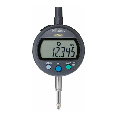
  9. Mitutoyo ID-SX User manual

Mitutoyo ID-SX User manual

Printed in Japan
Mitutoyo Corporation 1-20-1 Sakado, Takatsu-ku, Kawasaki City, Kanagawa 213-8533
ABS Digimatic Indicator ID-SX
en
Contents
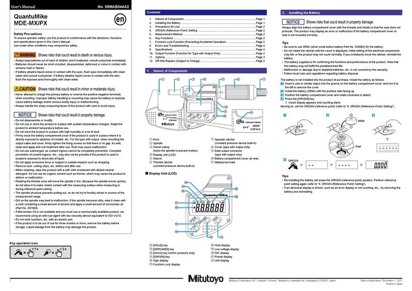
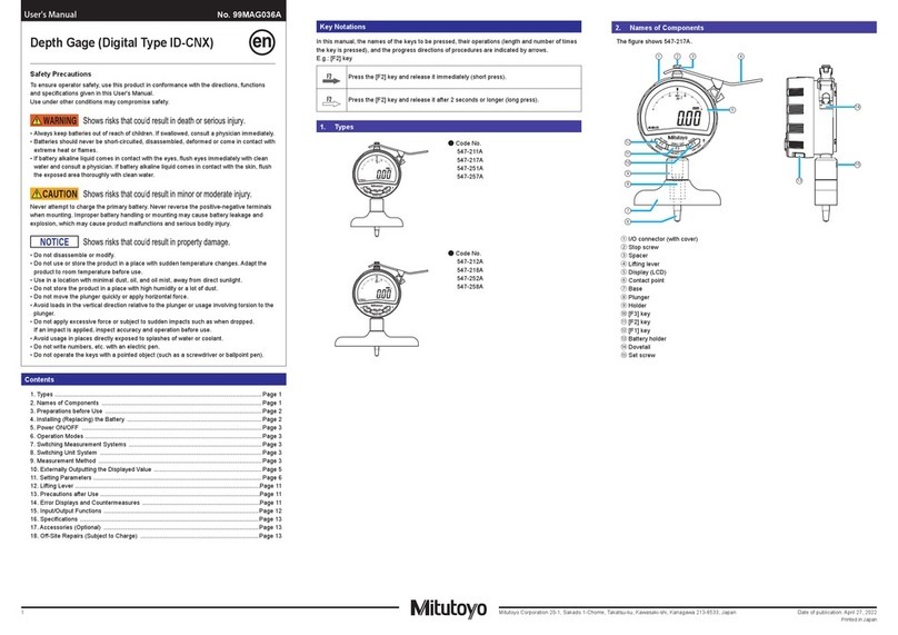
①Cap
②Battery holder
③Display (LCD)
④[ON/OFF] key
⑤[ORIGIN] key
⑥[in/mm] key (except for ID-S1012X,
ID-S112X, ID-S112PX)
⑦[+ / -] key
⑧Output connector (with cap)
⑨Lifting lever mount (left and right)
⑩Back with lug
⑪Flat back
⑫Release mounting hole (with rubber cap)
⑬Stem
⑭Spindle
⑮Contact point
⑯Rubber boot (dustproof type only)
Tips
Dimensions with an asterisk (*) are for the at back type. Dimensions without an asterisk (*) are
common for the back with lug type and the at back type.
■ Display (LCD)
①②
⑤
④
③
Key icon operation
=
> 2 s
=
< 1 s
2.  Installing (Replacing) the Battery
NOTICE
• Be sure to use SR44 (silver oxide button battery No. 938882) for the battery.
• The product may display an error or malfunction if the battery holder is not mounted correctly.
• If the product will be out of use for 3 months or more, remove the battery and store it
separately, to prevent damage to the product due to battery uid leakage.
• Do not use a pointed object or excessive force to remove the battery holder. This may damage
the battery holder.
SR44
31 5
2 4
1 Use a athead screwdriver or similar to remove the battery holder.
2 If replacing an existing battery, remove the old battery.
3 Insert a new battery into the battery holder with the "+" symbol facing the display (LCD).
4 Attach the battery holder.
5 Press the [ORIGIN] key for 1 second or more.
Tips
• If no value is displayed even when a battery is installed, reinstall the battery.
• Although the display may show garbled text, [E] (minimum digits) or [------] just after installing
the battery, this is not abnormal. Perform reference point setting as is (refer to "5. ORIGIN
Setting (Reference Point Setting)").
• Reference point settings are cleared when the battery is removed. Perform reference point
setting again after installing the battery.
①Unit display
②Measured value display
③Sign display
④Reverse count display
⑤Battery voltage decrease
display
Safety Precautions
To ensure operator safety, use this product in conformance with the directions, functions
and specications given in this User's Manual.
Use under other conditions may compromise safety.
WARNING
• Always keep batteries out of reach of children, and if swallowed, consult a physician im-
mediately.
• Batteries should never be short-circuited, disassembled, deformed or come in contact with
extreme heat or flames.
• If battery alkaline liquid comes in contact with the eyes, flush eyes immediately with clean
water and consult a physician. If battery alkaline liquid comes in contact with the skin,
flush the exposed area thoroughly with clean water.
CAUTION
• Never attempt to charge the primary battery or reverse the positive-negative terminals
when mounting. Improper battery handling or mounting may cause the battery to explode,
cause battery leakage and/ or serious bodily injury or malfunctioning.
• Always handle the sharp measuring faces of this product with care to avoid injury.
NOTICE
• Do not disassemble or modify. This may cause damage.
• Do not use or store the product in a place with sudden temperature changes. Adapt the
product to room temperature before use.
• Do not store the product in a place with high humidity or a lot of dust. Also, avoid usage in
places exposed to splashes of water or coolant.
• Do not apply excessive force or subject to sudden impacts such as dropping.
• Be sure to perform reference point setting before measurement.
• Remove dust, cutting chips, etc. before and after use.
• Do not write numbers, etc. with an electric pen. This may cause damage.
• Do not operate the keys with a pointed object (such as a screwdriver or ballpoint pen).
•
Avoid loads in the vertical direction relative to the spindle or usage involving torsion to the spindle.
• This product is shipped without a battery. Install a battery before use.
• The battery supplied is for conrming the functions and performance of the product. Note
that this battery may not fulll the expected life.
• When disposing of batteries, follow local laws, regulations, etc.
• Malfunction or damage due to depleted batteries, etc. is not covered by the warranty.
• The dustproof type protects the spindle and bearing from dust, water, oil, etc. by attaching
a rubber boot, etc. to the standard type. Note that the dustproof type is not completely
waterproof. Do not immerse the product in liquid or use the product in a place where it is
intensively exposed to oil or water.
• In environments with large temperature fluctuations, the measurement errors will increase
due to thermal expansion of parts and fixtures. Therefore use the product where the
temperature fluctuation is as little as possible.
When it is moved to a different temperature environment, allow sufficient time for the
product to thermally stabilize before use.
User's Manual No. 99MAH032A2
Date of publication: November 1, 2020
1.  Names and Dimensions of Components
NOTICE
The product display does not rotate. Forcibly rotating the display may damage the product.
■ ISO/JIS type
Back with lug type: ID-S1012X, -S1012MX, -S112X, -S112MX, -S112PX, -S112PMX
Flat back type*: ID-S1012XB, -S1012MXB, -S112XB, -S112MXB, -S112PXB, -S112PMXB
Unit: mm
Dustproof type
①
⑪
⑬
⑭
⑮
⑨
③
②
⑫
ø
6.5
M2.5x0.45
*
ø59
13.3
ø10.9
46.5
21.2
7.3
ø80
-0.009
7.6
54.4
50.1
20
5
16
17
19.9
ø54
⑯
⑩
⑧
⑦
⑥
⑤
④
ID-S112PX, ID-S112PXB,
ID-S112PMX, ID-S112PMXB
14
37.2
■ AGD type
Back with lug type: ID-S1012EX, -S112EX, -S112TX, -S112PEX
Flat back type*: ID-S1012EXB, -S112EXB, -S112TXB, -S112PEXB
Dustproof type
ø1/4
Thread
No.4-48UNF
3/8
ø2.32
0.58
0.46
0.52
ø.43
1.97
0.3*
1/4
ø9.52 mm
1/4
2
1.74
0.79
0
-0.03
ø2.12
0.63
3/4
0.78
1.46
ID-S112PEX, ID-S112PEXB
Unit: in
This is the symbol of American Gage Design (AGD). It means that this type conforms to
appropriate dimensions of Dial Indicators in ASME/AGD 2 and has interchangeability.
1.
Names and Dimensions of Components ......1
2. Installing (Replacing) the Battery .......... 1
3. Setup .................................................... 2
4. Power ON/OFF ..................................... 2
5. ORIGIN Setting ..................................... 2
(Reference Point Setting)
6. Measurement Method ........................... 3
7. Precautions after Use ........................... 3
8. Errors and Troubleshooting .................. 3
9. Rubber Boot Replacement .................. 3
(ID-S112PX, ID-S112PXB)
10. Output Function .................................... 3
11. Specications........................................ 4
12. Accessories (Optional).......................... 4
13. O󰀨-Site Repairs (Subject to Charge) .... 4
Printed in Japan
Mitutoyo Corporation 1-20-1 Sakado, Takatsu-ku, Kawasaki City, Kanagawa 213-8533
3.  Setup
1) Mounting to a stand, jig, etc.
NOTICE
• Whenever possible, avoid xing the stem directly with a set screw, etc.
• The spindle may not be able to move smoothly if the screw is tightened with a tightening torque
of 150 cN•m or more to secure the stem.
ø
8* mm
+0.0 2
+0.0 0 5
*ADG type:
ø
9.52 (3/8 in)
Tips
When mounting the product to a stand or jig, use the stem or lug on the back. If using the stem,
use a slotted holder with a ø8 mm or ø9.52 mm hole with G7 (+0.005 mm to +0.02 mm).
2) Mounting the lifting lever
[Options: Part No. 21EZA198 (mm), part No. 21EZA199 (in)]
NOTICE
•
Using the product while the stop screw is not secured rmly may damage internal components or the workpiece.
• If not mounting a stop screw, always mount the original screw on the spindle top end.
Otherwise internal components or the workpiece may be damaged.
12 3
1 Rotate the cap counterclockwise to remove it from the product.
2 Fix the spindle, using pliers padded with a rag, etc., so that it does not turn, and then remove
the screw (M2.5 or No.4-48UNF) at the top end of the spindle.
3Mount the stop screw supplied with the lifting lever and, with the lever tip caught by the stop
screw, mount the lifting lever on the lifting lever mount (dovetail).
Tips
Store the removed screw and cap to prevent loss.
3) Mounting the lifting knob
[Options: Part No. 21EZA105 (mm), part No. 21EZA150 (in)]
NOTICE
•
Using the product while the lifting knob is not secured rmly may damage internal components or the workpiece.
• If not mounting a lifting knob, always mount the original screw on the spindle top end.
Otherwise internal components or the workpiece may be damaged.
12 3
1 Rotate the cap counterclockwise to remove it from the product.
2 Fix the spindle, using pliers padded with a rag, etc., so that it does not turn, and then remove
the screw (M2.5 or No.4-48UNF) at the top end of the spindle.
3 Mount the lifting knob on the top end of the spindle.
Tips
Store the removed screw and cap to prevent loss.
4) Mounting the release (Optional part No. 540774)
NOTICE
• Always mount the rubber cap if a release is not mounted.
• The rubber cap is a screw-in type.
• The product may be damaged if an item other than the release is inserted or if excessive force
is applied.
• Raising or lowering the spindle while the release is not secured rmly may damage the internal
components.
1 Remove the rubber cap from the release mounting hole.
2 Screw the release rmly into the hole.
Tips
Store the removed screw and rubber cap to prevent loss.
5) Contact point replacement
NOTICE
When replacing the contact point, turn the contact point while xing the spindle. Otherwise, the
product may be damaged.
Mount and remove the contact point with a rag and 2 pairs of pliers (one for xing the spindle) as
shown in the gure.
Tips
• Changing the contact point may cause changes in external dimensions and measurement
force, or restrictions on measurement directions.
• Errors due to the contact point (perpendicularity of at contact point, center runout of roller con-
tact point, etc.) are added to the measurement accuracy.
• Various contact points are available as options. Refer to the Mitutoyo MEASURING INSTRU-
MENTS CATALOG for details.
4.  Power ON/OFF
ON/OFF
1 Press the [ON/OFF] key to turn the product on and o󰀨.
Tips
• If the power does not turn on even when the [ON/OFF] key is pressed, the battery may be
dead. Replace the battery.
• Although the spindle may feel heavy at the bottom dead center when using for the rst time,
this can be resolved by pushing the spindle up once.
•
Even after the power is turned o󰀨, the reference point set and counting direction will be retained.
5.  ORIGIN Setting (Reference Point Setting)
Master
ORIGIN
1Move the spindle to the point to be set as the reference point, and then press the [ORIGIN] key
for 1 second or more.
⇨ The indicated value becomes zero and the reference point (ORIGIN) is set.
Tips
• Place the contact point on the workpiece several times to verify that the measured value is stable.
• This product does not guarantee stable repeatability within 0.2 mm from the bottom dead
center (when the spindle is completely extended). When performing reference point setting, be
sure to lift the spindle at least 0.2 mm above the bottom dead center.
0.2 mm
• A rubber damper is attached to this product to soften the spindle impact. Although the indicated
value may not be stable at the bottom dead center due to the elasticity of the damper, this is
not a malfunction.
Stem
Printed in Japan
Mitutoyo Corporation 1-20-1 Sakado, Takatsu-ku, Kawasaki City, Kanagawa 213-8533
6.  Measurement Method
1) Measurement
Workpiece
1Gradually and lightly place the contact point on the workpiece in the same orientation and
conditions as for reference point setting, and then read the indicated value.
Tips
If the contact point strikes the workpiece to be measured hard, the workpiece may deform and
measurement results may be a󰀨ected.
2) Switching counting direction
The counting direction can be changed by pressing the [+/-] key. If the product is set to negative
counting when the spindle is pushed in, [▼] is shown on the top left of the display.
+/
-
+/
-
3) Switching units
Press the [in/mm] key to switch the unit between in (inches) and mm (millimeters).
in/mm
in/mm
7.  Precautions after Use
• When cleaning, wipe this product with a soft cloth moistened with diluted neutral detergent. Do
not use an organic solvent such as thinner, which may cause the product to deform or
malfunction.
• Dirt on the spindle may lead to malfunction. Clean with a cloth moistened with alcohol, etc. before
use.
• Do not lubricate the spindle with lubricating oil, etc.
• If the product is to be out of use for 3 months or more, remove the battery before storage. Liquid
leakage from the battery may damage the product.
• Do not store the product in a place with a high temperature or humidity, or a lot of dust or oil mist.
8.  Errors and Troubleshooting
Error Display Causes and Countermeasures
Battery voltage decrease mark Battery is depleted. Replace with a new battery.
Sensor contamination detection
error
A sudden change in temperature may create condensation on
the detector, or it may be contaminated by other sources.
Turn the power o󰀨 and allow the product to adapt to the
temperature for about 2 hours.
If it does not recover after adapting to the temperature, repair is
required: consult with your dealer or agent or with our sales
o󰀩ce.
Hardware error This error indicates a hardware abnormality. Repair is
necessary when the error is generated. Please contact our
sales o󰀩ce.
ABS synthesis error Although this may occur during high-speed spindle move-
ment, there is no e󰀨ect on measurement. Use the product as
is. If it occurs while the spindle is not moving, the internal
sensor has failed. In this case, repair is required: consult with
your dealer or agent or with our sales o󰀩ce.
9.  Rubber Boot Replacement (ID-S112PX, ID-112PXB)
Stem
Contact point
Rubber boot
(A)
ISO/JISAGD AGDISO/JIS
(B)
(A)
(B)
1Remove the old rubber boot and wipe away dust or oil from the stem groove (A) and spindle
groove (B) with alcohol, etc.
2Put the rubber boot on the spindle so that the rubber boot end with the larger bore is on the
stem side, and then set the rubber boot in between the stem and the contact point.
3Lightly apply a small amount of room temperature curing silicone adhesive to grooves (A) and
(B). At this time, be careful not to apply silicone adhesive to the spindle sliding surface.
4 Pinch the top end of the rubber boot with a tool such as at tip tweezers and t it into stem
groove (A).
5 Attach the bottom end of the rubber boot to spindle groove (B) by pressing manually.
6 Wipe away excess adhesive with a clean cloth.
10.  Output Function
NOTICE
For use with a Mitutoyo linear gage counter (EC-101D, EG-101D, EH-102D) connected, set the
linear gage counter "SDP input WAIT setting" to "No WAIT" before use. If used with other
settings, an error will be displayed on the linear gage counter.
1) Externally outputting the displayed value
The displayed value can be output to a device supporting Digimatic output format by connecting
the product and the external device with a connection cable (option). The product can be
connected to an optional external display, external printer, PC, etc.
12
Cap
Connection cable
1 Press the [ON/OFF] key to turn o󰀨 the product.
2 Connect the product and the external device.
1. Remove the cap of the output connector of the product.
2. Connect the product and the external device with a connection cable.
Tips
• 2 types of connection cables (options), No. 905338 (1 m) and No. 905409 (2 m), are available
for this product.
• When connecting a connection cable, pay attention to the connector direction as you insert it.
• Store the removed cap to prevent loss.
• Always install the cap if a connection cable is not used.
2) Output connector
Pin No. Signal I/O
(1) GND -
(2) DATA O
(3) CK O
(4) - -
(5) REQ I
• Input
• Output
REQ
DATA, CK
(1)
(5)
3) Output data format
(1) Output order
(2) All "F"
(3) Sign
(4) Measured
value
(5) Decimal
point
(6) Unit
4) Timing chart
2 (0100)
3 (1100)
4 (0010)
5 (1010)
(1)
MSD LSD
(5)
(2)(4)
(3)
+: 0 (0000)
–: 8 (0001)
(6)
mm: 0 (0000)
in: 1 (1000)
● Positive count
● Negative count
Printed in Japan
Mitutoyo Corporation 1-20-1 Sakado, Takatsu-ku, Kawasaki City, Kanagawa 213-8533
11.  Specications
■ Individual specications
Model *1
ID-S1012X, ID-S1012XB ID-S112X, ID-S112XB ID-S112PX, ID-S112PXB
Code No. *1 543-781, 543-781B 543-790, 534-790B 543-794, 543-794B
Measurement range 12.7 mm
Resolution 0.01 mm 0.001 mm
Error of indication for
the total measuring
range MPE
E
*2
0.02 mm 0.003 mm
Hysteresis
MPE
H
*2 0.02 mm 0.002 mm
Repeatability
MPE
R
*2 0.01 mm 0.002 mm
Stem diameter ø8 mm
Contact point Carbide (joint screw M2.5 x 0.45), part No. 901312 (provided as standard)
Measurement force
MPL 1.5 N or less 2.5 N or less
Measurement direction
All directions
Protection level *3 IP42 equivalent *4 IP53 equivalent *4
Battery life *5 Continuous operation
approx. 20,000 hours
Continuous operation approx. 18,000 hours
Model *1
ID-S1012MX, ID-S1012MXB
ID-S112MX, ID-S112MXB
ID-S112PMX, ID-S112PMXB
Code No. *1 543-782, 543-782B 543-791, 534-791B 543-795, 543-795B
Measurement range 12.7 mm/0.5 in
Resolution 0.01 mm/0.0005 in 0.001 mm/0.00005 in
Error of indication for
the total measuring
range MPE
E
*2
0.02 mm 0.003 mm
Hysteresis
MPE
H
*2 0.02 mm 0.002 mm
Repeatability
MPE
R
*2 0.01 mm 0.002 mm
Stem diameter ø8 mm
Contact point Carbide (joint screw M2.5 x 0.45), part No. 901312 (provided as standard)
Measurement force
MPL
1.5 N or less 2.5 N or less
Measurement direction
All directions
Protection level *3 IP42 equivalent *4 IP53 equivalent *4
Battery life *5 Continuous operation
approx. 20,000 hours
Continuous operation approx. 18,000 hours
Model *1
ID-S1012EX,
ID-S1012EXB
ID-S112EX,
ID-S112EXB
ID-S112TX,
ID-S112TXB
ID-S112PEX,
ID-S112PEXB
Code No. *1
543-783, 543-783B 543-793, 534-793B 543-792, 534-792B 543-796, 543-796B
Measurement range 0.5 in/12.7 mm
Resolution
0.0005 in/0.01 mm
0.00005 in/0.001 mm
0.0001 in/0.001 mm
0.00005 in/0.001 mm
Error of indication for
the total measuring
range MPE
E
*2
0.0020 in 0.0002 in
Hysteresis
MPE
H
*2 0.0010 in 0.0001 in
Repeatability
MPE
R
*2 0.0005 in 0.0001 in
Stem diameter 3/8 in diameter (ø9.52 mm)
Contact point Carbide (joint screw No. 4-48UNF), part No. 21BZB005 (provided as standard)
Measurement force
MPL 1.5 N or less 2.5 N or less
Measurement direction
All directions
Protection level *3 IP42 equivalent *4 IP53 equivalent *4
Battery life *5
Continuous operation
approx. 20,000 hours
Continuous operation approx. 18,000 hours
*1: Model numbers ending with "B" are at back types without lug.
*2: During normal measurement at 20 °C.
*3: The protection level (IP: International Protection) is based on IEC 60529/JIS C 0920.
*4: Values are for factory default conditions.
*5: The battery life varies depending on usage times and conditions. The above values are guidelines.
■ Common specications
CE Marking EMC Directive: EN 61326-1
Immunity test requirement: Clause 6.2 Table 2
Emission limit: Class B
RoHS Directive: EN IEC 63000
Power Silver oxide battery SR44 x 1 (part No. 938882)
Scale type Static capacitive type absolute linear encoder
Response speed Unlimited (unavailable for scanning measurement)
Data output Digimatic output
Temperature range
Operating temperature range: 0 °C to 40 °C, storage temperature range: -10 °C to 60 °C
Standard accessory
SR44 (for function verication x 1) • User's Manual warranty, inspection results
12.  Accessories (Optional)
• Lifting lever: Part No. 21EZA198 (mm)
• Lifting lever: Part No. 21EZA199 (in)
• Lifting knob: Part No. 21EZA105 (mm)
• Lifting knob: Part No. 21EZA150 (in)
• Release: Part No. 540774
• Connection cable: Part No. 905338 (1 m, at straight)
• Connection cable: Part No. 905409 (2 m, at straight)
* For accessories (optional) other than the above, refer to the Mitutoyo MEASURING INSTRU-
MENTS CATALOG.
13.  O󰀨-Site Repairs (Subject to Charge)
O󰀨-site repair (subject to charge) is required in the case of the following malfunctions. Contact your
nearest dealer or our sales o󰀩ce.
• Poor spindle operation
• Poor accuracy
• [E] is displayed as the last digit when the spindle is stationary
• Abnormal measured value or LCD trouble
• No recovery from [Err C]
• Power will not turn on
* If the fundamental structural components or multiple components need to be replaced, we reserve
the right to decline the repair.

This manual suits for next models

12

Other Mitutoyo Measuring Instrument manuals

Mitutoyo 209 Series User manual

Mitutoyo

Mitutoyo 209 Series User manual

Mitutoyo QM-Height User manual

Mitutoyo

Mitutoyo QM-Height User manual

Mitutoyo 99MAB034A1 User manual

Mitutoyo

Mitutoyo 99MAB034A1 User manual

Mitutoyo LSM-9506 User manual

Mitutoyo

Mitutoyo LSM-9506 User manual

Mitutoyo ACM User manual

Mitutoyo

Mitutoyo ACM User manual

Mitutoyo QM-Data 300 User manual

Mitutoyo

Mitutoyo QM-Data 300 User manual

Mitutoyo ABSOLUTE ID-F User manual

Mitutoyo

Mitutoyo ABSOLUTE ID-F User manual

Mitutoyo BOREMATIC User manual

Mitutoyo

Mitutoyo BOREMATIC User manual

Mitutoyo 7210 User manual

Mitutoyo

Mitutoyo 7210 User manual

Mitutoyo IT-012U User manual

Mitutoyo

Mitutoyo IT-012U User manual

Mitutoyo QM-Height QMH-350AX User manual

Mitutoyo

Mitutoyo QM-Height QMH-350AX User manual

Mitutoyo ID-C Series User manual

Mitutoyo

Mitutoyo ID-C Series User manual

Mitutoyo ID-U User manual

Mitutoyo

Mitutoyo ID-U User manual

Mitutoyo ID-H0530 User manual

Mitutoyo

Mitutoyo ID-H0530 User manual

Mitutoyo IMZ-MJ User manual

Mitutoyo

Mitutoyo IMZ-MJ User manual

Mitutoyo SURFTEST SV-3100 User manual

Mitutoyo

Mitutoyo SURFTEST SV-3100 User manual

Mitutoyo CG-S10A User manual

Mitutoyo

Mitutoyo CG-S10A User manual

Mitutoyo BMB-K User manual

Mitutoyo

Mitutoyo BMB-K User manual

Mitutoyo EJ-102N User manual

Mitutoyo

Mitutoyo EJ-102N User manual

Mitutoyo 572-200-20 User manual

Mitutoyo

Mitutoyo 572-200-20 User manual

Mitutoyo CONTRACER CV-2100 User manual

Mitutoyo

Mitutoyo CONTRACER CV-2100 User manual

Mitutoyo ID-C112GXB User manual

Mitutoyo

Mitutoyo ID-C112GXB User manual

Mitutoyo SJ-210 User manual

Mitutoyo

Mitutoyo SJ-210 User manual

Mitutoyo ID-N User manual

Mitutoyo

Mitutoyo ID-N User manual

Popular Measuring Instrument manuals by other brands

Neriox 111456 operating instructions

Neriox

Neriox 111456 operating instructions

vision microsystems VM 1000 Operator's guide

vision microsystems

vision microsystems VM 1000 Operator's guide

Shimmer Shimmer3 user guide

Shimmer

Shimmer Shimmer3 user guide

Ryobi P737D Operator's manual

Ryobi

Ryobi P737D Operator's manual

SPY DCPJM operating instructions

SPY

SPY DCPJM operating instructions

Ecom J2KNpro Tech operating instructions

Ecom

Ecom J2KNpro Tech operating instructions

POSTBERG+Co measuringSYSTEM MA-Di operating instructions

POSTBERG+Co

POSTBERG+Co measuringSYSTEM MA-Di operating instructions

Hanna Instruments HI7640-18 Series instruction manual

Hanna Instruments

Hanna Instruments HI7640-18 Series instruction manual

Honeywell GENT S4-34 Series Data and Installation

Honeywell

Honeywell GENT S4-34 Series Data and Installation

AEMT TIME MARK 2732 manual

AEMT

AEMT TIME MARK 2732 manual

HP 1660C Series Service guide

HP

HP 1660C Series Service guide

Alstom iSTAT M3x5 Series manual

Alstom

Alstom iSTAT M3x5 Series manual

Keysight N5241BU-229 installation guide

Keysight

Keysight N5241BU-229 installation guide

ENDA ETS762 manual

ENDA

ENDA ETS762 manual

Aranet 4 HOME user manual

Aranet

Aranet 4 HOME user manual

Tianlan TM-103N user manual

Tianlan

Tianlan TM-103N user manual

BYK spectro2guide manual

BYK

BYK spectro2guide manual

Badger Meter PortaSonic 9000 user manual

Badger Meter

Badger Meter PortaSonic 9000 user manual

manuals.online logo
manuals.online logoBrands
  • About & Mission
  • Contact us
  • Privacy Policy
  • Terms and Conditions

Copyright 2025 Manuals.Online. All Rights Reserved.