encelium.com
Copyright © 2021 Digital Lumens, Incorporated. All rights reserved. Digital Lumens, the Digital
Lumens logo, We Generate Facility Wellness, SiteWorx, LightRules, Lightelligence, Encelium,
the Encelium logo, Polaris, GreenBus and any other trademark, service mark, or tradename
(collectively “the Marks”) are either trademarks or registered trademarks of Digital Lumens,
Inc. in the United States and/or other countries, or remain the property of their respective
owners that have granted Digital Lumens, Inc. the right and license to use such Marks and/or
are used herein as nominative fair use. Due to continuous improvements and innovations,
specifications may change without notice.
DOC-000439-00 Rev A 11-21
TROUBLESHOOTING
There are no user-serviceable parts inside. For detailed information about how to set-up, install, use, and maintain Encelium
hardware and software, please visit: help.encelium.com
REGULATORY APPROVAL
Modifications not expressly approved by the manufacturer could void the user’s authority to operate the equipment under FCC rules.
This equipment has been tested and found to comply with the limits for a Class A digital device, pursuant to part 15 of the FCC
Rules. These limits are designed to provide reasonable protection against harmful interference when the equipment is operated in
a commercial environment. This equipment generates, uses, and can radiate radio frequency energy and, if not installed and used in
accordance with the installation instructions, may cause harmful interference to radio communications. Operation of this equipment
in a residential area is likely to cause harmful interference in which case the user will be required to correct the interference at his own
expense.
Contains FCC ID: H79DFZM-E7220
Contains IC ID: 4259B-DFZM7220
Notes: This equipment has been tested and found to comply with Industry Canada ICES-003 Issue 5 (CAN ICES-3 (A)/NMB-3 (A).
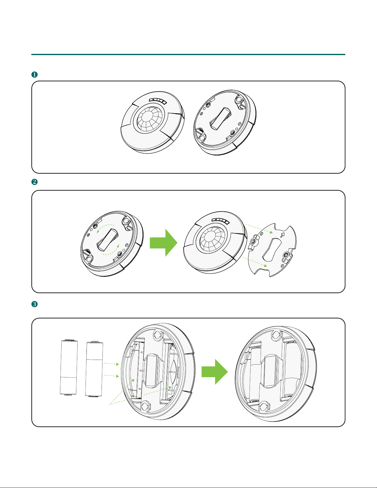
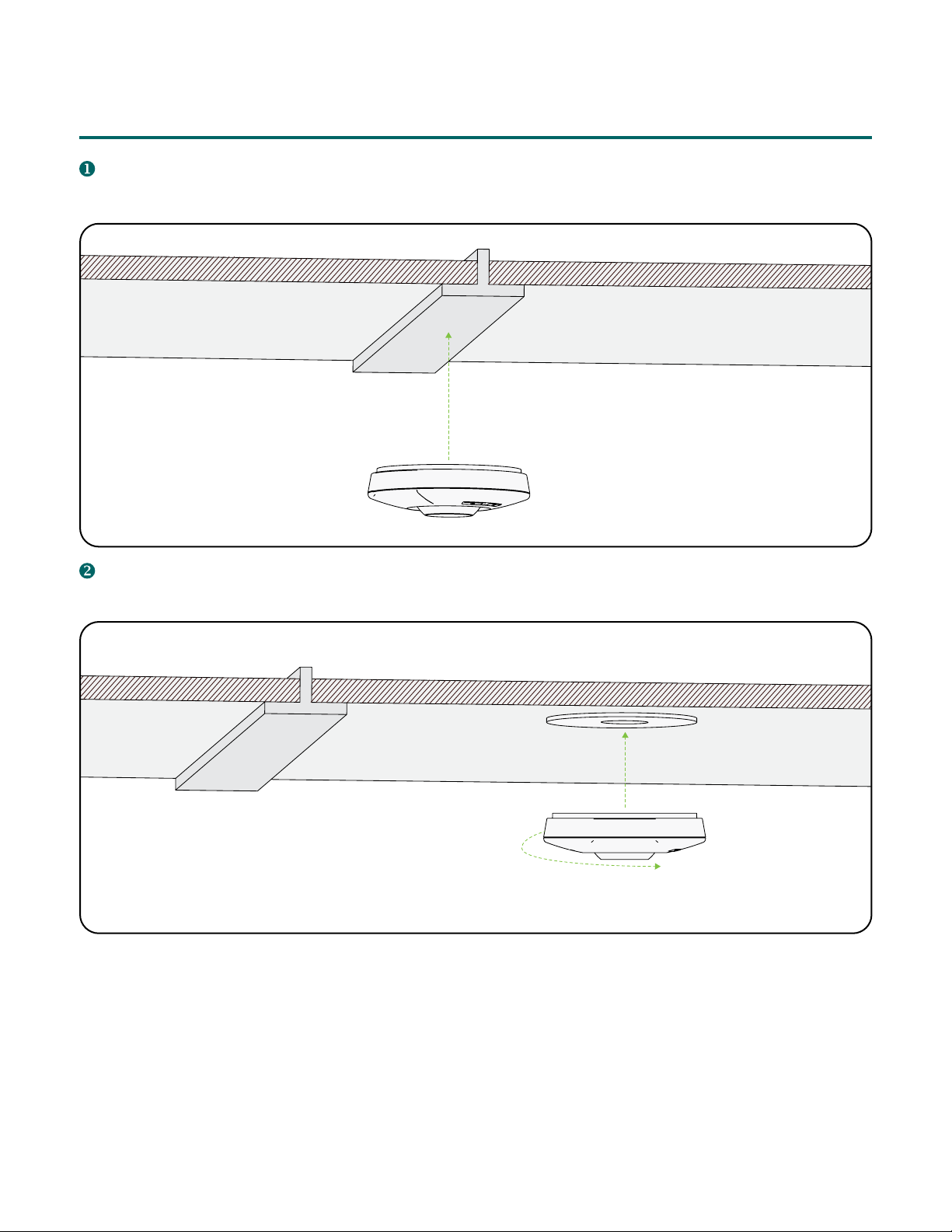
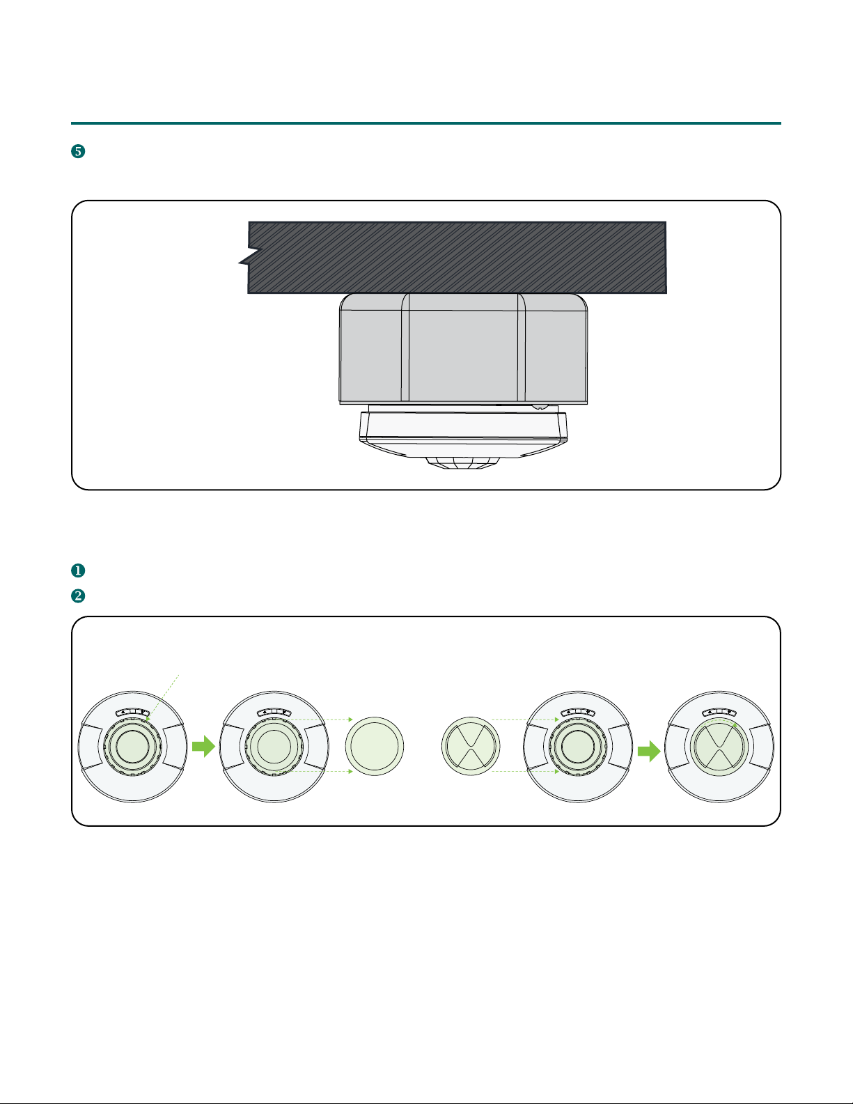
Wireless Ceiling Mount Sensor INSTALLATION
INSTRUCTIONS