Encyclon 651SP-MWTT Manual

6705 14th Avenue • PO Box 1258 •
Kenosha, WI
53143
Phone 800/767-3551 • 262/654-0032 • Fax 262/657-7435 •www.encyclon.com •
sales@encyclon.com
Encyclon Inc.
Cyclonic Filtration Systems
INSTALLATION OPERATION
AND
MAINTENANCE INSTRUCTIONS
FOR
ENCYCLON FILTRATION SYSTEMS
MODEL NO. 651SP-MWTT
SERIAL NO. 20347

INDEX
INDEX 1
PRE-TEXT & WARNINGS 2
DESCRIPTION OF THE FILTER SYSTEM 3 - 4
START-UP PROCEDURE 5
SYSTEM OPERATION 6
TROUBLESHOOTING & MAINTENANCE 7
FILTER CIRCUIT LAYOUT 8
REPAIR PARTS LIST & DRAWING 9 - 10
ELECTRICAL CONTROL – HUBBELL BOOKLET
FILTER PUMP- GUSHER BOOKLET
CLEAN PUMP – WEL-BILT BOOKLET
PRESSURE WASH SECONDARY FILTER

PRE-TEXT & WARNINGS
In order that this ENCYCLON filtration system may give
continuous, satisfactory and safe service it is necessary
that the filter be properly installed, operated and
maintained. Please review this instruction book
thoroughly before installation and operation of the filter.
WARNINGS
Caution is advised when installing this system. The
hoses and piping should never be used for lifting
purposes.
The system should be plugged into a 120V / 1 / 60 Hz
minimum 20 Amp GFCI receptacle.
DO NOT service the system while in operation.
DO NOT place hands in front of pump suction port
while the system is running.
FAILURE TO FOLLOW THESE INSTRUCTIONS MAY
RESULT IN SERIOUS PERSONAL SHOCK, INJURY
OR DEATH.
Page 2

ENCYCLON SYSTEM DESCRIPTION
The ENCYCLON filtration system continuously cleans
and filters wash water without using filter media to
provide clean water for your application.
The ENCYCLON hydrocyclone is the core of a
continuous filtration system for water applications. The
cyclone removes metallic and non-metallic particles as
small as 5 microns with a specific gravity greater than
1.5. Through continuous filtration and aeration of the
water by the cyclones, bacteria growth is retarded, thus
preventing the water from becoming rancid.
Page 3

Page 4
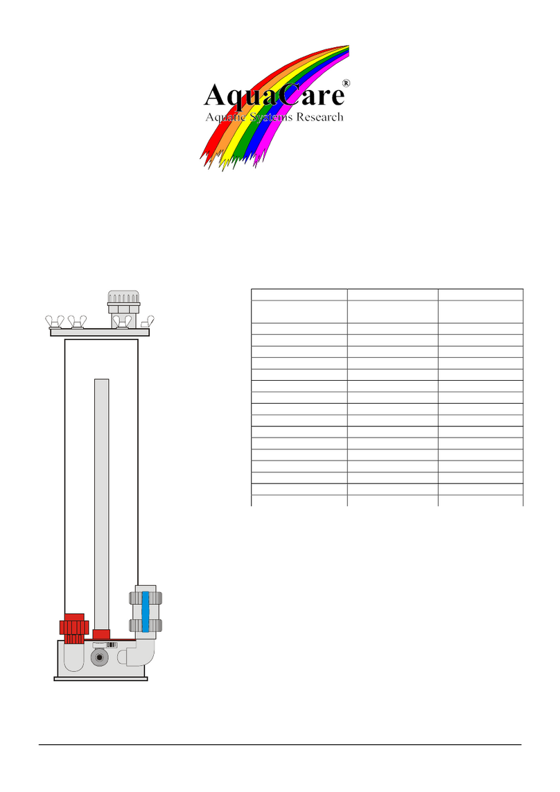
Here’s How Cyclonic Filtration Works
Dirty liquid enters the cyclone at the inlet orifice (1) of the cyclonic chamber (3).
The shape and tangential location of the orifice develop a downward, spiraling
flow of the liquid. This is called the primary whirl (4) which follows the chamber
walls downward, developing centrifugal force of up to 7500 times that of gravity.
This same force spins out the solid particles
to 5 microns, or .00019” diameter from the
liquid. The solid particles (often referred to as
swarf) strike the wall and slide down to the
discharge orifice (7).
A throttling effect in the lower cyclonic
chamber (6) reverses the descent of the
liquid but not the rotation. This forms the
secondary whirl (5), a rising, spiraling flow of
cleaned liquid that passes up through the
primary whirl to the whirl searcher (2).
The diameter of the whirl searcher is smaller
than the secondary whirl, and the whirl
searcher accepts only the center of the
upward, secondary whirl flow.
The outside portion of the secondary whirl
(containing impurities missed by the primary
whirl) is diverted back to the primary whirl for
further cleansing. This double cleansing
action is significant to the efficiency of the
Encyclon Cyclonic Filtration Systems.
Liquid that passes through the whirl searcher
is then piped out to the clean water storage
tank or can be directly used with 5 micron
filtration with 98% efficiency.
There are no filter media to clog or replace.
Encyclon aerates water to check anaerobic
bacterial growth.

START-UP PROCEDURE
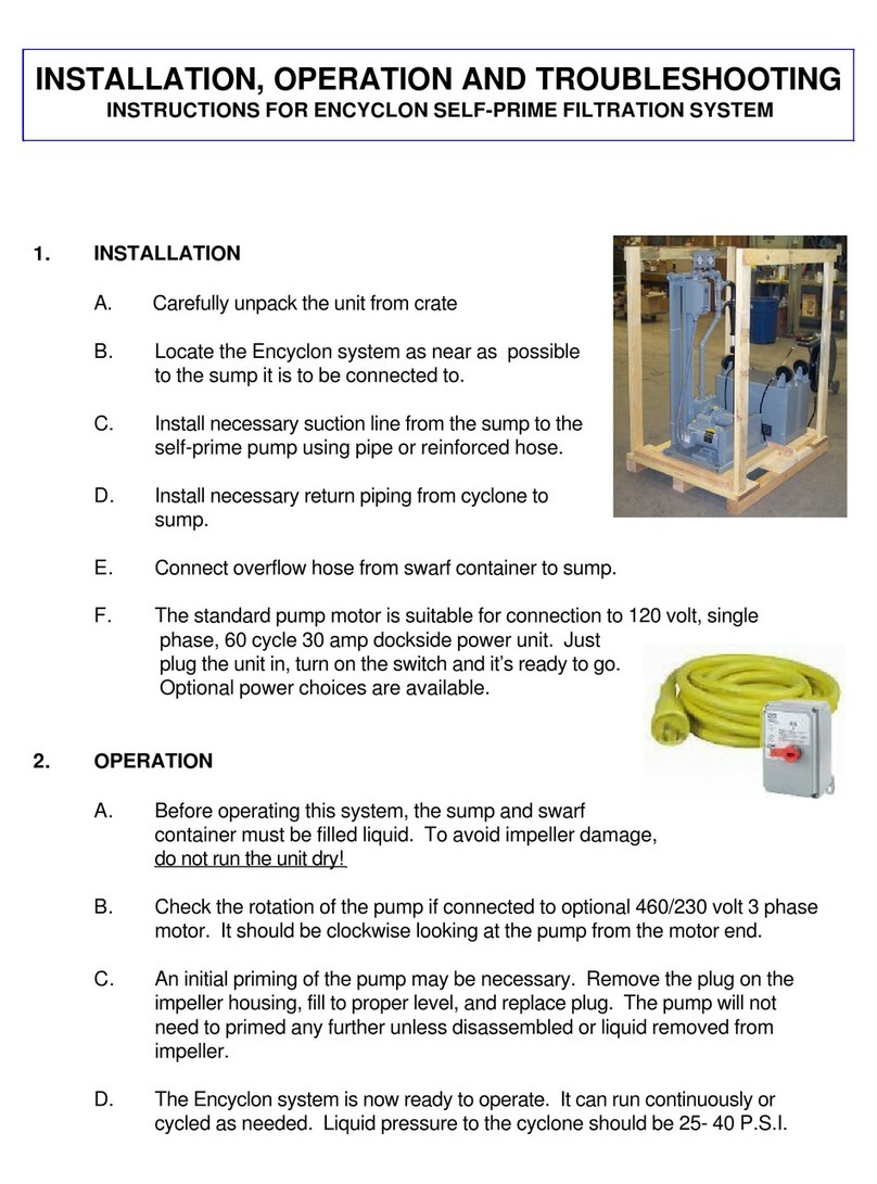
1. Locate the ENCYCLON system as close as possible to the below grade
sump.
2. Fill the “Clean Tank” (Front) first, then the “Dirty Tank” (Rear) and then the
“Swarf Container” with clean water up to the overflow fittings.
3. Prime both pumps by removing the plugs on the impeller housings. Open
1-1/2” Ball Valve leading to the Cyclone Pump. Open 1” Ball Valve
leading to the Clean Pump. DO NOT open 1” Ball valves attached to the
drain of each tank as these are only used for drainage of the tanks.
4. Attach the supplied 1” hose to the 1” fitting on top of the “Dirty Tank” and
the other end to the below grade “Sump Pump” supplied by others.
5. The Dirty Tank 2” overflow hose, and the 1-1/2” overflow hose from the
Swarf Container should be directed towards the wash pad or below grade
sump.
6. Make sure the “ON / OFF” rotary control for both pumps is in the “OFF”
position. Plug shore cord into a minimum 120 Volt / 1 / 60 Hz, 20 Amp
outlet.
7. Turn Cyclone Pump “ON”, Turn Clean Pump “ON” using the rotary switch.
The Clean Pump has a separate ON/OFF rocker switch which is in the
“ON” position from the factory. The Clean Pump will not function without
the Cyclone pump running.
8. Connect pressure washer to hose bib and open valve.
Page 5

SYSTEM OPERATION
1. Both tanks and the swarf container should be filled up to the overflow
fittings.
2. Make sure the below grade sump is filled up to the height of the return
from the wash pad. Connect the Sump Pump to the supplied 1” hose, and
then connect the other end to the 1” fitting on top of the dirty tank.
3. Connect the power washer hose to the hose bib on the trailer and open
the valve.
4. The ENCYCLON filter system is now ready to operate. During the wash
operation, the ENCYCLON system should be run continuously and can be
run after the wash operation is shut down if further filtration is desired or
required.
5. Turn “ON /OFF” control to “ON” position for the Cyclone Pump. Inlet
pressure to the cyclone should be 25 – 40 P.S.I. and the outlet pressure
should be less than 10 P.S.I.
6. When mud appears on the surface of the swarf container, it must be
emptied to prevent swarf from re-entering the below grade sump.
7. Keep water levels in all tanks up throughout the washing operation.
8. Cyclone Pump can run continuous as it is set up for closed loop operation,
and the Clean Pump can run continuous as a pressure switch is used.
9. Make sure the Sump Pump does not send more liquid to the Dirty Tank
than 20 GPM. This can be controlled with a ball valve on the Sump Pump.
The Dirty Tank has an overflow to return excess water back to the sump.
10. The system will have a running water level of approximately 120 gallons in
the Clean Tank and a running level in the Dirty Tank of approximately 110
gallons. The 2” overflow line should be directed back to the sump.
11. If the pressure washer is pulsing purge the secondary filter by opening the
red valve for a few seconds to clear it.
NOTE: Cyclone pump must be ON before the clean pump can be turned
ON. Finally the pressure washer can be turned ON.
Page 6

TROUBLESHOOTING & MAINTENANCE
Normally the ENCYCLON system needs no maintenance. However, there are
some things to watch for. Most problems can be detected by monitoring the
pressure gauges mounted on the cyclone manifold assembly.
1. Low “Cyclone In” pressure below 25 P.S.I. gauge
A. Disassemble and check for obstruction in suction line from
the dirty tank to the pump.
B. Disassemble and check for obstructions in pump casing and
impeller.
C. Disassemble and check for obstructions in pressure line.
2. High “Cyclone Out” pressure above 10 P.S.I. gauge
A. Check for obstruction in the piping from the cyclone to the
clean tank.
B. Check for clogged cyclone assembly.
3. Clogging of nozzles
A. Stop pump motor and unscrew the cap nut that secures the
ceramic nozzle.
B. The cleaning of the nozzle and the conical part of the cyclone
is done with a wire of about 1/8 inch in diameter rounded off at
the end, so that there is no damage done to the inside cone
surface.
C. Reassemble nozzle after cleaning by reversing above step.
4. Clean pump surging
A. Purge the secondary filter by opening the red valve while the
clean pump is running for a few seconds to clear the filter.
Page 7

Page 8

RECOMMENDED REPAIR PARTS
When ordering repair parts the following should be given to
assure delivery of proper parts for your filter system.
1. Model No.:
2. Serial No.:
3. Part No.:
4. Quantity:
5. Description:
6. Send Order To: Encyclon, Inc.
6705 14th Avenue
Kenosha, WI 5314
800-767-3551
262-657-7435 – Fax
Part No. Qty. Description Page
650-023 1 Pressure Gauge 0-30 N/A
650-024 1 Pressure Gauge 0-60 N/A
274-125 1 90 degree Hose 10
200-002 4 Hose Clamp 10
601-001 1 Inlet Nozzle 10
957-003 1 2-1/2” O’ Ring 10
602-001 1 Cone Shaped Casing 10
957-002 1 1” O’ Ring 10
603-001 1 Cap Nut 10
604-001 1 Ceramic Nozzle 10
605-001 1 Spray Protector 10
282-125 1 Straight Hose 10
800-117 1 Filter Pump / Gusher 2 H.P. N/A
RH30425 1 Pump Mechanical Seal N/A
61051-EPDM 1 Pump Housing Gasket N/A
800-123 1 Clean Pump – “WEL-BILT” N/A
Page 9

Table of contents
Other Encyclon Water Filtration System manuals
