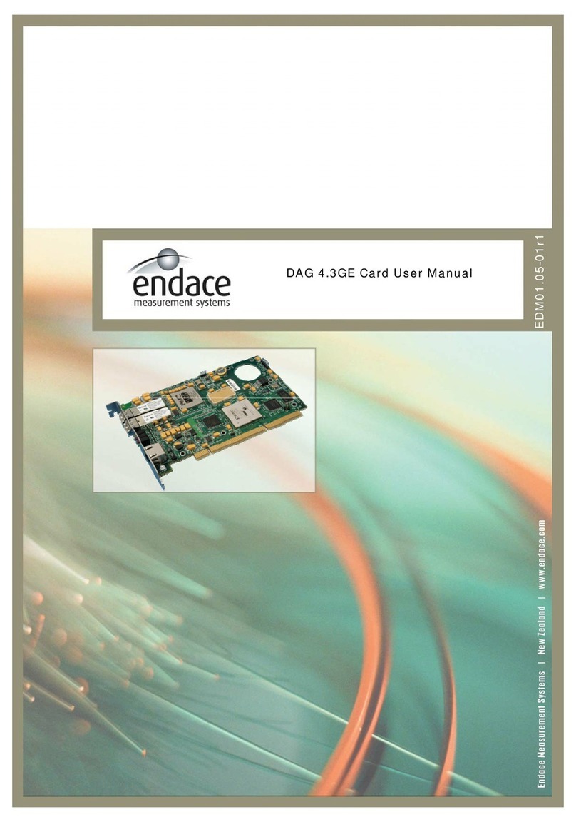
Endace DAG 3.7T User manual


EDM01-12: DAG 3.7T Card User Guide
Published by:
Endace Measurement Systems®Ltd
Building 7
17 Lambie Drive
PO Box 76802
Manukau City 1702
New Zealand
Phone: +64 9 262 7260
Fax: +64 9 262 7261
EDM01 05
12r1
www.endace.com
International Locations
New Zealand
Endace Technology® Ltd
Americas
Endace USA® Ltd
Europe, Middle East & Africa
Endace Europe® Ltd
Level 9
85 Alexandra Street
PO Box 19246
Hamilton 2001
New Zealand
Suite 220
11495 Sunset Hill Road
Reston
Virginia 20190
United States of America
Sheraton House
Castle Park
Cambridge CB3 0AX
United Kingdom
Phone: +64 7 839 0540
Fax: +64 7 839 0543
Phone: ++1 703 382 0155
Fax: ++1 703 382 0155
Phone: ++44 1223 370 176
Fax: ++44 1223 370 040
Copyright 2005 ©All rights reserved. No part of this publication may be reproduced, stored in a retrieval system,
or transmitted, in any form or by any means electronic, mechanical, photocopying, recording, or otherwise, without
the prior written permission of the publisher.
Version 10: May 2006 ©2005

EDM01-12: DAG 3.7T Card User Guide
Pro
Whe
spec 5
of th
Thes
com
This
instr
Ope
requ
Extr
The
oper
Com
mate
equi
Disc
Whi
the c
resu
Enda
resp
In ac
subj
tection Against Harmful Interference
n present on equipment this manual pertains to, the statement "This device complies with part 15 of the FCC rules"
ifies the equipment has been tested and found to comply with the limits for a Class A digital device, pursuant to Part 1
e Federal Communications Commission [FCC] Rules.
e limits are designed to provide reasonable protection against harmful interference when the equipment is operated in a
mercial environment.
equipment generates, uses, and can radiate radio frequency energy and, if not installed and used in accordance with the
uction manual, may cause harmful interference to radio communications.
ration of this equipment in a residential area is likely to cause harmful interference in which case the user will be
ired to correct the interference at his own expense.
a Components and Materials
product that this manual pertains to may include extra components and materials that are not essential to its basic
ation, but are necessary to ensure compliance to the product standards required by the United States Federal
munications Commission, and the European EMC Directive. Modification or removal of these components and/or
rials, is liable to cause non compliance to these standards, and in doing so invalidate the user’s right to operate this
pment in a Class A industrial environment.
laimer
lst every effort has been made to ensure accuracy, neither Endace Measurement Systems Limited nor any employee of
ompany, shall be liable on any ground whatsoever to any party in respect of decisions or actions they may make as a
lt of using this information.
ce Measurement Systems Limited has taken great effort to verify the accuracy of this manual, but assumes no
onsibility for any technical inaccuracies or typographical errors.
cordance with the Endace Measurement Systems policy of continuing development, design and specifications are
ect to change without notice.
©2005 Version 10: May 2006


EDM01-12: DAG 3.7T Card User Guide
Table of Contents
Chapter 1: Introduction 1
Overview 1
Purpose of this User Guide 1
System Requirements 1
Card Description 3
Card Architecture 4
Extended Functions 5
Chapter 2: Installation 7
Introduction 7
DAG Device Driver 7
Inserting the DAG Card 7
Mounting the Pod 7
Connecting the Pod to the PC 8
Connecting the Interfaces 8
Connecting to the Network 9
Chapter 3: Configuring the Card 11
Introduction 11
Line Characteristics 11
LEDs and Inputs 12
Load the FPGA Image 13
Display Current Configuration 13
Mode Options 14
Default Configuration 15
Configuring the Links 15
Interface Statistics 16
Help 18
Chapter 4: Configuring HDLC Connections 19
Overview 19
Configuration File 19
Multiple Interfaces 19
Receive/ Transmit 20
Connection ID 20
Output Record Formats 20
Connection Types 21
Hyper-Channel Connection [h] 21
Timeslot Connection [c] 22
Sub-channel Connection [s] 22
Line Connection [l] 22
RAW Connection [r] 22
Line RAW Connection [lr] 23
Channel RAW Connection [cr] 23
Hyper-Channel RAW Connection [hr] 23
Sub-Channel RAW Connection [sr] 23
Delete Connection [d] 23
©2005 i Version 10: May 2006

EDM01-12: DAG 3.7T Card User Guide
Chapter 5: Configuring ATM Connections 25
Overview 25
Configuration File 25
Multiple Interfaces 25
Receive/ Transmit 26
Output Record Formats 26
Connection Types 26
Hyper-Channel Connection [h] 26
Timeslot Connection [c] 27
Line Connection [l] 27
ATM Scrambling on Interface [t] 28
HEC Connection on Interface [f] 28
Delete Connection [d] 28
Chapter 6: Configuring Mixed ATM and HDLC Connections 29
Using Mixed Firmware 29
Chapter 7: Capturing Data 31
Starting a Session 31
High Load Performance 31
Configuring Extended Functions 33
Overview 33
Loading the Images 33
Starting the XScale 34
Directing Data to the XScale 34
Using the AAL Reassembler 34
Using the IMA Monitor 35
Using the HDLC Filter 35
Using HDLC and IMA Together 36
Chapter 8: Synchronizing Clock Time 37
Overview 37
DUCK Configuration 37
Common Synchronization 37
Timestamps 38
Configuration Tools 39
Card with Reference 40
Single Card No Reference 41
Two Cards No Reference 41
Connector Pin-outs 43
Chapter 9: Data Formats 45
Overview 45
Generic Header 45
Type 5 Record 47
Type 6 Record 48
Type 7 Record 49
Type 8 Record 50
Type 9 Record 51
Type 12 Record 52
Chapter 10 Troubleshooting 53
Reporting Problems 53
Version 10: May 2006 ii ©2005

EDM01-12: DAG 3.7T Card User Guide
Chapter 1:
Introduction
Overview Endace DAG 3.7T card provides the means to transfer data at the full speed
of the network into the memory of the host PC, with zero packet loss
guaranteed in even worst-case conditions. Further, unlike a NIC, Endace
products actively manage the movement of network data into memory
without consuming any of the host PC's resources. The full attention of the
CPU remains focused on the analysis of incoming data without a constant
stream of interruptions as new packets arrive from the network. For a busy
network link, this feature has a turbo-charging effect similar to that of adding
a second CPU to the system.
The DAG3.7T is a Network Monitoring Interface Card specifically designed
to perform high efficiency monitoring and transmission with precision
timestamping capability on up to sixteen T1/E1 network links.
Purpose of
this User
Guide
The purpose of this User Guide is to provide you with an understanding of
the DAG card architecture and functionality and to guide you through the
following:
•Installing the card and associated software and firmware,
•Configuring the card for your specific network requirements,
•Running a data capture session,
•Synchronising clock time,
•Data formats.
You can also find additional information relating to functions and features of
the DAG 3.7T card in the following documents which are available from the
Support section of the Endace website at www.endace.com:
•EDM04-08 Configuration and Status API Programming Guide,
•EDM04-12 DAG 3.7T HDLC Filtering Guide,
•EDM04-13 SAR API Programming Guide.
This User Guide and the Linux and Window Guides are also available in PDF
format on the Installation CD shipped with your DAG 3.7T card.
System
Requirements General
The minimum system requirements for the DAG 3.7T card are :
•PC, at least Intel Xeon 1.4GHz or faster,
•256 MB RAM,
•At least one free PCI 2.1 slot supporting 33MHz operation,
•Software distribution free space of 30MB.
©2005 1 Version 10: May 2006

EDM01-12: DAG 3.7T Card User Guide
Operating System
This User Guide assumes you are installing the DAG card in a PC which
already has an operating system installed.
However for convenience, a copy of Debian Linux 3.1 (Sarge) is provided as
a bootable ISO image on the CDs that is shipped with the DAG card.
To install either the Linux/FreeBSD or Windows operating system please
refer to the following documents which are also included on the CD that is
shipped with the DAG card.
•EDM04-01 Linux FreeBSD Software Installation Guide
•EDM 04-02 Windows Software Installation Guide
Other Systems
For advice on using an operating system that is substantially different from
either of those specified above, please contact Endace Customer Support at
Version 10: May 2006 2 ©2005

EDM01-12: DAG 3.7T Card User Guide
Card
Description
The DAG 3.7T cards are PCI bus cards designed for cell and packet capture
and generation over IP networks. The key features of the card are:
•Support for an external pod housing 16 RJ-45 T1/E1 network
interfaces,
•A Spartan III FPGA supporting high-performance Endace firmware,
•An Intel 80321 XScale IO processor which supports AAL2/AAL5
reassembly or inverse multiplexing over ATM (IMA) and filtering
services,
•Support for receiving and sending channelised, unchannelised, and
fractional T1/E1, HDLC and non-HDLC data traffic,
•Support for data traffic filtering.
Exar Framer
Chips XScale
Processo
r
VHDCI
Connector
FPGA
VHDCI
connector
RJ45
Connector
Pod Front View
16 x RJ-45 connectors
Pod Rear View
VHDCI Connector
©2005 3 Version 10: May 2006

EDM01-12: DAG 3.7T Card User Guide
Card
Architecture
T1 or E1 data is received on up to 16 x RJ-45 interfaces, and passes through
line interface units. It then feeds immediately into the FPGA for deframing
and demapping into ATM or HDLC frames.
The FPGA contains an Ethernet processor and the DAG Universal Clock Kit
(DUCK) timestamp engine. The DUCK provides high resolution per packet
timestamps which can be accurately synchronised. Time stamped packet
records are then stored in the lower FIFO.
Note: For further in formation on the DUCK and time synchronising
please refer to Chapter 8: Synchronising Clock Time later in this User
Guide.
An Intel 80321 XScale processor is logically located next to the main FPGA.
The XScale processor provides the facility to pre-process data before it is
presented to the host, or before being transmitted over an E1/T1 link. It can
also facilitate hostless operation via an embedded Linux kernel.
The main FPGA can route packets to either the XScale processor before
routing onto the host, or directly to the host via the PCI port.
The following diagram shows the card’s major components and the flow of
data.
Version 10: May 2006 4 ©2005

EDM01-12: DAG 3.7T Card User Guide
Extended
Functions
The DAG 3.7T card supports the following extended functions:
•AAL2/AAL5 segmentation and reassembly,
•Inverse Multiplexing ATM (IMA),
•HDLC Filtering.
These functions are described in more detail in Chapter 7: Capturing Data
later in this User Guide and also in the following documents available from
•SAR API Programming Guide,
•IMA API Programming Guide,
•HDLC Filtering Guide.
©2005 5 Version 10: May 2006

EDM01-12: DAG 3.7T Card User Guide
Version 10: May 2006 6 ©2005

EDM01-12: DAG 3.7T Card User Guide
Chapter 2:
Installation
Introduction A DAG 3.7T card can be installed in any free PCI slot. It is 5V tolerant and
operates only in 32-bit 33MHz PCI mode.
If you install the card into a slot that is rated for higher speeds it will cause
the bus to automatically change to 33MHz. This will also affect any other
devices which may be sharing the bus.
You can run multiple DAG 3.7T cards on one bus. By default, the DAG
driver supports up to four DAG cards in one system.
DAG Device
Driver
The DAG device driver must be installed before you install the DAG card
itself.
If you have not already completed this please follow the instructions in
EDM04-01 Linux FreeBSD Software Installation Guide or EDM 04-02
Windows Software Installation Guide as appropriate, which are included on
the CD shipped with the DAG card.
Inserting the
DAG Card
To insert the DAG card in the PC follow the steps described below:
•Turn power to the computer OFF,
•Remove the PCI bus slot screw and cover,
•Insert DAG card into PCI bus slot ensuring that it is firmly seated in the
slot,
•Check the free end of the card fits securely into the card-end bracket
that supports the weight of the card,
•Secure the card with the bus slot screw,
•Turn power to the computer ON.
Mounting the
Pod Note: You can connect only one pod to the card at any one time
You can mount the 3.7T breakout pod either internally in a spare 5.25 inch
drive bay in the PC chassis, or sit it separately outside of the PC chassis.
The pod and the DAG card connect via a VHDCI cable. The card has one
VHDCI connector located on the PCI bracket and another one on the card
itself. The pod has one VHDCI connector located externally on the rear of the
casing.
If the pod is mounted internally in the PC you will need to connect to the card
using the connector located on the card itself.
If the pod is external to the PC chassis you will need to connect to the card
using the connector located on the card PCI bracket.
©2005 7 Version 10: May 2006

EDM01-12: DAG 3.7T Card User Guide
Connecting
the Pod to the
PC
Connect the pod to the DAG card using the 68-pin VHDCI cable supplied
with the card as shown below.
The picture below shows the pod and DAG card connected using the external
connector on the card. Use this configuration when the pod is not mounted in
the PC chassis.
The picture below show the pod and the DAG card connected using the
connector located on the card itself. Use this configuration when the pod is
mounted in the PC chassis.
Connecting
the Interfaces
The RJ45 connector cables for connecting the network interfaces to the pod
are not supplied with the DAG card or the pod. You must source these
yourself.
If you have an Endace pod you will be able to use standard E1/T1 cables
available from your local electronic stockist.
If you have another type of pod you will need to make the cables up yourself
to match the pod pinouts shown in the following tables.
Note: You can identify the standard Endace pod by the web address
“www.endace.com” written on the front of the casing above the top
row of RJ45 sockets.
Version 10: May 2006 8 ©2005

EDM01-12: DAG 3.7T Card User Guide
Connecting
the Interfaces
(cont.)
The physical pinouts of the RJ-45 connectors for both the Endace and other
types of pod are shown below:
Endace Pod Other Pod
1 1
TX Tip
2 2
TX Ring
3
3 TX Ring
4 4
RX Tip TX Tip
5 5
RX Ring RX Ring
6
6 RX Tip
7
7
8
8
Connecting to
the Network
Once you have connected the interfaces to the pod you must connect the
interfaces to the network via a tap as shown in the diagram below:
You must use a separate tap for each interface.
Note: For further information about using taps to connect to the
network please consult your network administrator.
When you have connected the pod to the DAG Card and the network
interfaces to the network you must configure the card for your specific
requirements. This process is described next in Chapter 3: Card
Configuration.
©2005 9 Version 10: May 2006

EDM01-12: DAG 3.7T Card User Guide
Version 10: May 2006 10 ©2005

EDM01-12: DAG 3.7T Card User Guide
Chapter 3:
Configuring the Card
Introduction Configuring the DAG card for data capture involves the following steps:
•Loading an image and programming the FPGA,
•Setting the link,
•Checking the link,
•Configuring the connections,
•Capturing data.
The DAG 3.7T card uses two integrated Exar Octal T1/E1 Framer Chips
which each provide support for up to 8 EI/T1interfaces. The dagthree tool
which is supplied with the DAG card allows you to configure the card via the
Exar chips for a range of physical line characteristics according to your
network requirements. dagthree also provides access to interface statistics.
The dagchan tool which is also supplied with the DAG card allows you to
configure channel characteristics. Sample dagthree and dagchan outputs
are shown later in this chapter.
Line
Characteristics Overview
It is important that you understand the physical characteristics of the network
to which you want to connect before you begin configuring the card.
The flexibility provided by the Exar chips means that the card will accept a
wide range of settings. However if they are not the correct settings for your
network the card will not function as expected.
Note: If you are unsure about which of the options listed below apply
to your network, please contact your Network Administrator for further
information before proceeding with configuring the card.
Supported Options
The line characteristics supported by the DAG 3.7T card are described below.
Line Type: •E1: European digital standard 2 Mbps,
•E1 CRC: E1 with cyclic redundancy check,
•T1: North American digital standard 1.544 Mbps,
•T1 SF: Super frame, (also called D4 framing). An SF
is 12 frames long,
•T1 ESF: Extended super frame,(also called D5
framing), includes CRC and bandwidth for a data link
channel. An ESF is 24 frames long.
©2005 11 Version 10: May 2006

EDM01-12: DAG 3.7T Card User Guide
Line
Characteristics
(cont)
Encoding
Type: •B8ZS: Bipolar with Eight Zero Substitution (T1
only)/HDB3 Hi-density Bipolar Three zeros(E1
only),
•AMI Alternate Mark Inversion.
Cable Type: •Externally terminated,
•75unbalanced coaxial cable (E1 only),
•100balanced twisted pair (T1 only),
•120balanced twisted pair (E1 only).
Signal
Attenuation: •<-15dB short haul,
•<-36dB long haul,
•<-43dB extended long haul.
LEDs and
Inputs
Before you begin to configure the DAG card it is important to understand the
function of the various LEDs associated with the card, as well as the sockets
on the PCI bracket.
Coaxial Connector for Line
Synchronisation Input
VHDCI
Connector
RJ45 socket for time
Synchronisation Input 1
2
3
4
The LED functions are described below:
LED Description
1 FPGA successfully programmed.
2 Data capture in progress
PPS (pulse per second) Out: indicates the card is
sending a clock synchronisation signal
3
PPS (pulse per second) In: indicates the card is
sending a clock synchronisation signal
4
Version 10: May 2006 12 ©2005

EDM01-12: DAG 3.7T Card User Guide
Note: Before you can configure the card you must first load the card
with the appropriate FPGA image for the type of data you want to
capture. It is important you understand the protocol used by the
network to which you want to connect. If you do not load the correct
image for the protocol you will not be able to capture data.
Load the
FPGA Image
•For High Level Data Link Control (HDLC) capture use:
dagrom –rvp –d dag0 –f xilinx/dag37tpci-hdlc-erf.bit
•For Asynchronous Transfer Mode (ATM) capture use:
dagrom –rvp –d dag0 –f xilinx/dag37tpci-atm-erf.bit
•For ATM and HDLC capture use:
dagrom –rvp –d dag0 –f xilinx/dag37tpci-mixed-erf.bit
Note: The mixed FPGA image does not support transmit.
Display
Current
Configuration
•Once you have loaded the appropriate image you should run the
dagthree tool without arguments to display the current card
configuration using:
dagthree –d dag0 (where dag0 is the device number of the DAG card)
An explanation of an example dagthree output is shown below:
Receive and transmit termination,
encoding and line type as defined
b
y
the selected Mode.
Unsets (nofcl) or sets (fcl)
facility loopback. Note: fcl
loops back to the line.
Resets or clears
the framer status
links 0-7 clear E1
links 8-15 noreset T1
link 0 mode=29 rxpkts txpkts nofcl eql rxterm120 txterm120 b8zs/hdb3 E1
link 1 mode=29 rxpkts txpkts nofcl eql rxterm120 txterm120 b8zs/hdb3 E1
link 2 mode=29 rxpkts txpkts nofcl eql rxterm120 txterm120 b8zs/hdb3 E1
link 3 mode=29 rxpkts txpkts nofcl eql rxterm120 txterm120 b8zs/hdb3 E1
link 4 mode=29 rxpkts txpkts nofcl eql rxterm120 txterm120 b8zs/hdb3 E1
link 5 mode=29 rxpkts txpkts nofcl eql rxterm120 txterm120 b8zs/hdb3 E1
link 6 mode=29 rxpkts txpkts nofcl eql rxterm120 txterm120 b8zs/hdb3 E1
link 7 mode=29 rxpkts txpkts nofcl eql rxterm120 txterm120 b8zs/hdb3 E1
link 8 mode=8 rxpkts txpkts nofcl eql rxterm120 txterm120 b8zs/hdb3 T1
link 9 mode=8 rxpkts txpkts nofcl eql rxterm100 txterm100 b8zs/hdb3 T1
link 10 mode=8 rxpkts txpkts nofcl eql rxterm100 txterm100 b8zs/hdb3 T1
link 11 mode=8 rxpkts txpkts nofcl eql rxterm100 txterm100 b8zs/hdb3 T1
link 12 mode=8 rxpkts txpkts nofcl eql rxterm100 txterm100 b8zs/hdb3 T1
link 13 mode=8 rxpkts txpkts nofcl eql rxterm100 txterm100 b8zs/hdb3 T1
link 14 mode=8 rxpkts txpkts nofcl eql rxterm100 txterm100 b8zs/hdb3 T1
link 15 mode=8 rxpkts txpkts nofcl eql rxterm100 txterm100 b8zs/hdb3 T1
pci 33MHz 32-bit buf=32MiB rxstreams=1 txstreams=1 mem=24:8
Firmware:dag37tpci_erf-atm_pci_v2_33 3s1500fg456 2006/03/28 18:14:59
(user)
time stamp head
Corresponds toRJ-
45 connections 0-15
on pod
Indicates the specific line
characteristics as
described in the Mode
table below
Unsets (noeql) or sets (eql)
equipment loopback. Note: eql
loops back to the PCI bus.
Enables(rxpkts) or
disables (norxpkts) the
receive stream
Enables (txplts) or
disables (notxpkts) the
transmit stream
Total memory available to the
DAG card in Windows this
32MB. In Linux it is 128mMB
Timestamp is recorded at the start
(head) or end (tail) of a received
packet.
Memory in MiB allocated
to receive (24MiB) and
t
r
ansmit
(
8MiB
)
streams.
©2005 13 Version 10: May 2006

EDM01-12: DAG 3.7T Card User Guide
Mode Options The table below describes the different line characteristics associated with
each of the supported modes.
Note: Ensure that the mode you select matches the physical
characteristics of the network to which you want to connect.
Mode Type Tx LBO Cable Coding
0 T1 Long Haul/36dB 0dB 100/ TP B8ZS
1 T1 Long Haul/36dB -7.5dB 100/ TP B8ZS
2 T1 Long Haul/36dB -15dB 100/ TP B8ZS
3 T1 Long Haul/36dB -22.5dB 100/ TP B8ZS
4 T1 Long Haul/45dB 0dB 100/ TP B8ZS
5 T1 Long Haul/45dB -7.5dB 100/ TP B8ZS
6 T1 Long Haul/45dB -15dB 100/ TP B8ZS
7 T1 Long Haul/45dB -22.5dB 100/ TP B8ZS
8 T1 Short Haul/15dB 0-133 ft./ 0.6dB 100/ TP B8ZS
9 T1 Short Haul/15dB 133-266 ft./ 1.2dB 100/ TP B8ZS
10 T1 Short Haul/15dB 266-399 ft./ 1.8dB 100/ TP B8ZS
11 T1 Short Haul/15dB 399-533 ft./ 2.4dB 100/ TP B8ZS
12 T1 Short Haul/15dB 533-655 ft./ 3.0dB 100/ TP B8ZS
13 T1 Short Haul/15dB Arbitrary Pulse 100/ TP B8ZS
14 T1 Gain Mode/29dB 0-133 ft./ 0.6dB 100/ TP B8ZS
15 T1 Gain Mode/29dB 133-266 ft./ 1.2dB 100/ TP B8ZS
16 T1 Gain Mode/29dB 266-399 ft./ 1.8dB 100/ TP B8ZS
17 T1 Gain Mode/29dB 399-533 ft./ 2.4dB 100/ TP B8ZS
18 T1 Gain Mode/29dB 533-655 ft./ 3.0dB 100/ TP B8ZS
19 T1 Gain Mode/29dB Arbitrary Pulse 100/ TP B8ZS
20 T1 Gain Mode/29dB 0dB 100/ TP B8ZS
21 T1 Gain Mode/29dB -7.5dB 100/ TP B8ZS
22 T1 Gain Mode/29dB -15dB 100/ TP B8ZS
23 T1 Gain Mode/29dB -22.5dB 100/ TP B8ZS
24 E1 Long Haul/36dB ITU G.703/Arbitrary 75/ coax HDB3
25 E1 Long Haul/36dB ITU G.703/Arbitrary 120/ TP HDB3
26 E1 Long Haul/43dB ITU G.703/Arbitrary 75/ coax HDB3
27 E1 Long Haul/43dB ITU G.703/Arbitrary 120/ TP HDB3
28 E1 Short Haul ITU G.703/Arbitrary 75/ coax HDB3
29 E1 Short Haul ITU G.703/Arbitrary 120/ TP HDB3
30 E1 Gain Mode ITU G.703/Arbitrary 75/ coax HDB3
31 E1 Gain Mode ITU G.703/Arbitrary 120/ TP HDB3
Version 10: May 2006 14 ©2005
Other manuals for DAG 3.7T
2
Table of contents
Other Endace PCI Card manuals
Popular PCI Card manuals by other brands

Texas Instruments
Texas Instruments SW14J59EVM JESD204C user guide
IEI Technology
IEI Technology LAN-10G2SF-PHY-CS4227 Quick installation guide
Amulet Hotkey
Amulet Hotkey DXH4 user manual
DeLOCK
DeLOCK 89592 user manual
Conexant
Conexant Intersil ISL39000M OEM INSTALLATION MANUAL

Conrad
Conrad 46 93 97 Operation instructions
