Endace DAG 4.3GE User manual

EDM01.05-01r1
DAG 4.3GE Card User Manual

Endace Measurement Systems Ltd EDM01.05-01r1 DAG 4.3GE Card User Manual
www.endace.com
Copyright© All rights reserved Revision 6. 22 September 2005.
Leading Network Intelligence
Copyright © 2005.
Published by:
Endace Measurement Systems®Ltd
Building 7
17 Lambie Drive
PO Box 76802
Manukau City 1702
New Zealand
Phone: +64 9 262 7260
Fax: +64 9 262 7261
www.endace.com
International Locations
New Zealand Americas Europe, Middle East & Africa
Endace Technology®Ltd
Level 9
85 Alexandra Street
PO Box 19246
Hamilton 2001
New Zealand
Phone: +64 7 839 0540
Fax: +64 7 839 0543
www.endace.com
Endace USA®Ltd
Suite 220
11495 Sunset Hill Road
Reston
Virginia 20190
United States of America
Phone: ++1 703 382 0155
Fax: ++1 703 382 0155
www.endace.com
Endace Europe®Ltd
Sheraton House
Castle Park
Cambridge CB3 0AX
United Kingdom
Phone: ++44 1223 370 176
Fax: ++44 1223 370 040
www.endace.com
All rights reserved. No part of this publication may be reproduced, stored in a retrieval system, or transmitted, in
any form or by any means electronic, mechanical, photocopying, recording, or otherwise, without the prior
written permission of the publisher. Prepared in Hamilton, New Zealand.

Endace Measurement Systems Ltd EDM01.05-01r1 DAG 4.3GE Card User Manual
www.endace.com
Copyright© All rights reserved Revision 6. 22 September 2005.
Typographical Conventions Used in this Document
•Command-line examples suitable for entering at command prompts are displayed in
mono-space courier font. The font is also used to describe config file data
used as examples within a sentence. An example can be in more than one sentence.
Results generated by example command-lines are also displayed in mono-space
courier font.
•The software version references such as 2.3.x, 2.4.x, 2.5.x are specific to Endace
Measurement Systems and relate to Company software products only.
Protection Against Harmful Interference
When present on product this manual pertains to and indicated by product labelling, the statement "This device complies
with part 15 of the FCC rules" specifies the equipment has been tested and found to comply with the limits for a Class A
digital device, pursuant to Part 15 of the Federal Communications Commission [FCC] Rules.
These limits are designed to provide reasonable protection against harmful interference when the equipment is operated in a
commercial environment.
This equipment generates, uses, and can radiate radio frequency energy and, if not installed and used in accordance with the
instruction manual, may cause harmful interference to radio communications.
Operation of this equipment in a residential area is likely to cause harmful interference in which case the user will be
required to correct the interference at his own expense.
Extra Components and Materials
The product that this manual pertains to may include extra components and materials that are not essential to its basic
operation, but are necessary to ensure compliance to the product standards required by the United States Federal
Communications Commission, and the European EMC Directive. Modification or removal of these components and/or
materials, is liable to cause non compliance to these standards, and in doing so invalidate the user’s right to operate this
equipment in a Class A industrial environment.

Endace Measurement Systems Ltd EDM01.05-01r1 DAG 4.3GE Card User Manual
www.endace.com
Table of Contents
1.0 PREFACE...........................................................................................................................1
1.1 User Manual Purpose......................................................................................................1
1.2 DAG 4.3GE Card Product Description...........................................................................2
1.3 DAG 4.3GE Card Architecture.......................................................................................2
1.4 DAG 4.3GE Card Extended Functions...........................................................................3
1.5 DAG 4.3GE Card System Requirements........................................................................4
2.0 INSTALLING DAG 4.3GE CARD..................................................................................5
2.1 Installation of Operating System and Endace Software..................................................5
2.2 Insert DAG 4.3GE Card into PC.....................................................................................5
2.3 DAG 4.3GE Card Port Connectors.................................................................................6
2.4 Pluggable Optical Transceivers.......................................................................................6
3.0 SETTING OPTICAL POWER ........................................................................................9
3.1 Optical Power Input ........................................................................................................9
3.2 Splitter Losses...............................................................................................................10
4.0 CONFIDENCE TESTING..............................................................................................11
4.1 Interpreting DAG 4.3GE Card LED Status...................................................................11
4.2 DAG 4.3GE Card LED Display Functions...................................................................12
4.3 Configuration in WYSYCC Style.................................................................................13
4.4 DAG 4.3GE Card Capture Session...............................................................................14
4.5 Inspect Interface Statistics.............................................................................................15
4.6 Reporting Problems.......................................................................................................17
5.0 RUNNING DATA CAPTURE SOFTWARE................................................................19
5.1 Starting Capture Session...............................................................................................19
5.2 High Load Performance................................................................................................22
5.3 DAG 4.3GE Card Packet Transmission Capabilities....................................................23
5.3.1 DAG Packet Transmission......................................................................................23
5.3.2 Inline Forwarding....................................................................................................26
6.0 SYNCHRONIZING CLOCK TIME..............................................................................27
6.1 Configurations Tool Usage...........................................................................................28
6.2 Time Synchronization Configurations..........................................................................29
6.2.1 Single Card no Reference Time Synchronization...................................................29
6.2.2 Two Cards no Reference Time Synchronization....................................................30
6.2.3 Card with Reference Time Synchronization...........................................................31
6.3 Synchronization Connector Pin-outs.............................................................................33
7.0 DATA FORMATS OVERVIEW....................................................................................35
7.1 Data Formats.................................................................................................................35
7.2 Timestamps...................................................................................................................37
Copyright© All rights reserved iRevision 6. 22 September 2005.

Endace Measurement Systems Ltd EDM01.05-01r1 DAG 4.3GE Card User Manual
www.endace.com
USE THIS SPACE FOR NOTES
Copyright© All rights reserved ii Revision 6. 22 September 2005.

Endace Measurement Systems Ltd EDM01.05-01r1 DAG 4.3GE Card User Manual
www.endace.com
1.0 PREFACE
Introduction The installation of the Endace DAG 4.3GE card on a PC begins with
installing the operating system and the Endace software. This is followed
by fitting the card and connecting the ports.
Viewing this
document This document, DAG 4.3GE Card User Manual is available on the
installation CD.
In this chapter This chapter covers the following sections of information.
•User Manual Purpose
•DAG 4.3GE Card Product Description
•DAG 4.3GE Card Architecture
•DAG 4.3GE Card Extended Functions
•DAG 4.3GE Card System Requirements
1.1 User Manual Purpose
Description The purpose of this DAG 4.3GE Card User Manual is to describe:
•Installing DAG 4.3GE Card
•Setting Optical Power
•Confidence Testing
•Running Data Capture Software
•Synchronizing Clock Time
•Data Formats Overview
Pre-requisite This document presumes the DAG card is being installed in a PC already
configured with an operating system.
A copy of the Debian Linux 3.1 (Sarge) is available as a bootable ISO
image on one of the CD's shipped with the DAG card.
To install on the Linux/FreeBSD operating system, follow the instructions
in the document EDM04.05-01r1 Linux FreeBSD Installation Manual,
packaged in the CD shipped with the DAG card.
To install on a Windows operating system, follow the instructions in the
document EDM04.05-02r1 Windows Installation Manual, packaged in the
CD shipped with the DAG card
Copyright© All rights reserved 1Revision 6. 22 September 2005.

Endace Measurement Systems Ltd EDM01.05-01r1 DAG 4.3GE Card User Manual
www.endace.com
1.2 DAG 4.3GE Card Product Description
Description The DAG 4.3GE card is a PCI-X bus card designed for cell and packet
capture and generation on Ethernet networks.
Figure Figure 1-1 shows the DAG 4.3GE PCI-X card.
Figure 1-1. DAG 4.3GE PCI-X Card.
The DAG 4.3GE card collects packet header and payload from Ethernet
networks and is protocol independent. Full packet capture at line rate
allows recording of all header information and/or payload with a high
precision timestamp.
The DAG 4.3GE is capable of transmitting packets at 100% line rate on
both ports while simultaneously receiving packets at 100% line rate on
both ports.
1.3 DAG 4.3GE Card Architecture
Description Serial Ethernet optical network data received by two 1000baseSX optical
interfaces flow into an Ethernet Framer ASIC then immediately into the
Field-Programmable Gate Array [FPGA].
The FPGA contains an Endace DAG Universal Clock Kit [DUCK]
timestamp engine, packet record processor, and PCI-X interface logic.
Because of component close association, packets or cells are time-stamped
accurately. Time stamped packet records are stored in an external FIFO
memory before transmission to the host.
Continued on next page
Copyright© All rights reserved 2Revision 6. 22 September 2005.

Endace Measurement Systems Ltd EDM01.05-01r1 DAG 4.3GE Card User Manual
www.endace.com
1.3 DAG 4.3GE Card Architecture, continued
Figure Figure 1-2 shows the DAG 4.3GE Card major components and process
flow.
Rx
Tx Optics Module
Tx
Rx Optics Module
Framer
Coprocessor
Connector
DAG 4.3
FPGA CPLD
Time Stamping
Clock Flash
ROM
LED’s
FIFO
Sync
In/Out
PCI-X 64-bit 66-133MHz
Figure 1-2. DAG 4.3GE Card Major Components and Data Flow.
1.4 DAG 4.3GE Card Extended Functions
Description The DAG 4.3GE card is equipped with a coprocessor connector which can
be used with the optional Endace DAG Coprocessor as a data processing
tool.
The IP packet classification specifications are:
•Packets are classified by TCP/IP header fields and/or payload
content.
•Up to 16,384 TCP/IP header classification rules. Up to ~2,000
arbitrary payload search strings.
•Classification rules are assigned a user-defined 16-bit identifier
•Packets matching classification rules are assigned the matching
rule's identifier.
•Programmable actions may be associated with each rule identifier.
For example, The packet should either be dropped, retransmitted to
the network, or presented to the host.
•Packets presented to the host include the rule-match identifier in the
record header.
enable effective use of extended functions.
Copyright© All rights reserved 3Revision 6. 22 September 2005.

Endace Measurement Systems Ltd EDM01.05-01r1 DAG 4.3GE Card User Manual
www.endace.com
1.5 DAG 4.3GE Card System Requirements
Description The DAG 4.3GE card and associated data capture system minimum
operating requirements are:
•PC, at least Intel Xeon 1.8GHz or faster
•Intel E7500, ServerWorks Grand Champion LE/HE, or newer chip
set
•256 MB RAM
•At least one free PCI-X 1.0 slot supporting 66-133MHz operation
•Software distribution free space of 30MB
Operating
system For convenience, the Debian 3.1 [Sarge] Linux system is included on the
Endace Software Install CD. Endace currently supports Windows XP,
Windows Server 2000, Windows Server 2003, FreeBSD, RHEL 3.0, and
Debian Linux operating systems.
Different
system For advice on using a system substantially different from that specified
Copyright© All rights reserved 4Revision 6. 22 September 2005.

Endace Measurement Systems Ltd EDM01.05-01r1 DAG 4.3GE Card User Manual
www.endace.com
2.0 INSTALLING DAG 4.3GE CARD
Introduction The DAG 4.3GE card can be installed in any free PCI-X 1.0 slot. It will
operate at 66, 100, or 133MHz PCI-X mode, however it will not operate
correctly in 32 or 64-bit PCI slots.
Higher speed slots are recommended for best performance.
The DAG 4.3GE should be the only device on the PCI-X bus if possible
as the cards make very heavy use of PCI-X bus data transfer resources.
Although the driver supports up to four DAG cards by default in one
system, due to bandwidth limitations there should not be more than one
card on a single PCI-X bus.
In this section This section covers the following topics of information.
•Installation of Operating System and Endace Software
•Insert DAG 4.3GE Card into PC
•DAG 4.3GE Card Port Connectors
•Pluggable Optical Transceivers
2.1 Installation of Operating System and Endace Software
Description If the DAG device driver is not installed, before proceeding with the next
chapter, install the software by following the instructions in EDM04-01
Linux/FreeBSD Installation Guide.
To install the software on a Windows operating system, follow the
instructions in EDM04-02 Windows Installation Guide.
Go to the next chapter of information when the DAG device driver is
installed.
2.2 Insert DAG 4.3GE Card into PC
Description Inserting the DAG 4.3GE card into a PC involves accessing the PCI-X bus
slot, fitting the card, and secure the bus slot screw.
Procedure Follow these steps to insert the DAG 4.3GE card.
Step 1. Access bus Slot
Power computer down.
Remove PCI-X bus slot cover.
Continued on next page
Copyright© All rights reserved 5Revision 6. 22 September 2005.

Endace Measurement Systems Ltd EDM01.05-01r1 DAG 4.3GE Card User Manual
www.endace.com
2.2 Insert DAG 4.3GE Card into PC, continued
Procedure, continued
Step 2. Fit Card
Insert DAG 4.3GE card into PCI-X bus slot.
Step 3. Replace bus Slot Screw
Secure card with screw.
Step 4. Power Up Computer
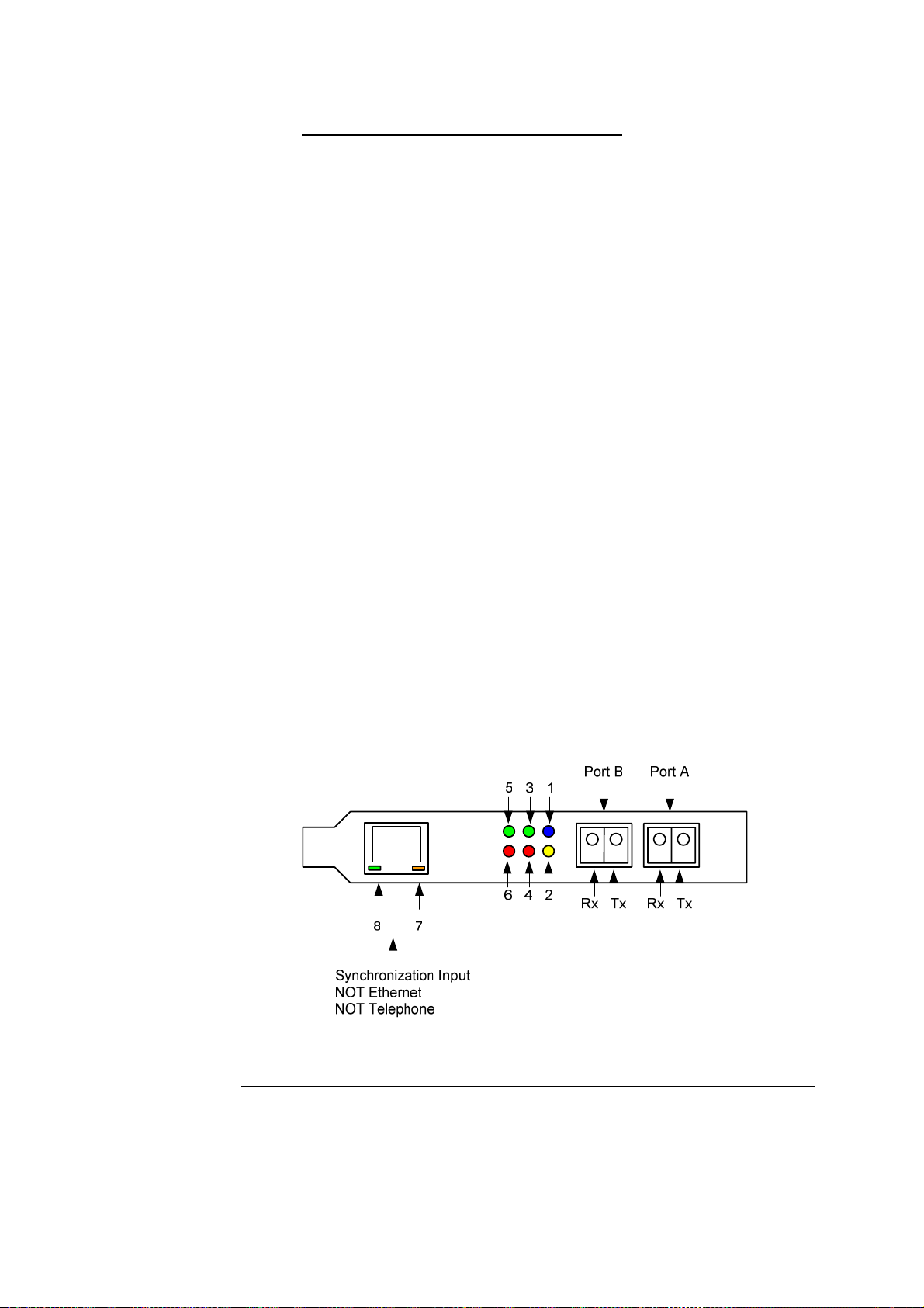
2.3 DAG 4.3GE Card Port Connectors
Description There are two duplex LC-type optical port connectors. Each port consists
of an optical fibre transmitter and receiver.
The upper connection of each pair is for transmitting signals. They are
connected only if loop-back facility is used in the DAG to daisy-chain the
systems. They are also connected if a data generation program is being
used.
The bottom connectors for each pair are used for the received signal.
An 8-pin RJ45 socket is used for time synchronization. This socket
should never be connected to an Ethernet network or telephone line.
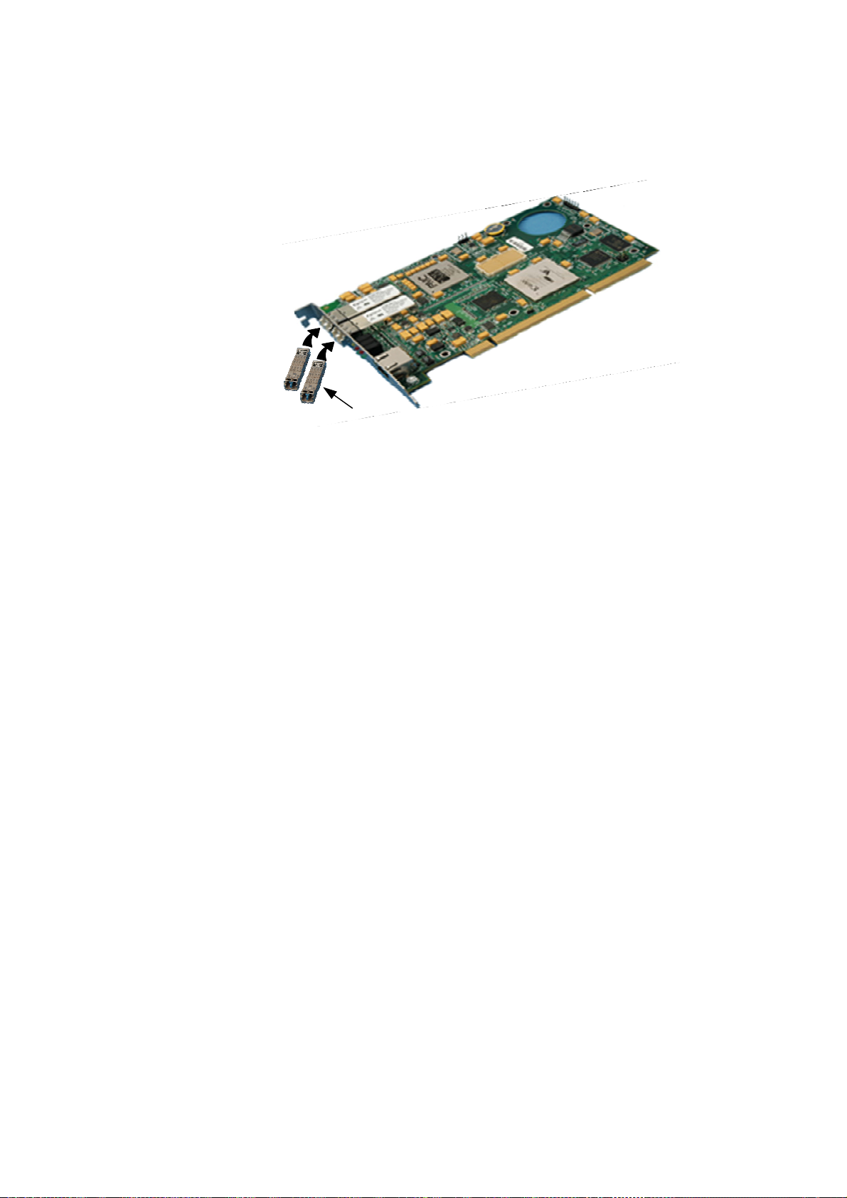
2.4 Pluggable Optical Transceivers
Description Some newer versions of the DAG 4.3GE cards are available with
pluggable optics. To provide compatibility with the broadest possible
range of optical parameters, Endace offers the industry standard Small
Form-factor Pluggable [SFP] optical transceiver on the DAG 4.3GE card.
The SFP transceiver consists of two parts:
•Mechanical chassis attached to the circuit board
•Transceiver unit which may be inserted into the chassis
The correct transceiver is chosen to suit the optical parameters of the
target network installed in the chassis.
The transceiver may then be connected to the network via LC-style optical
connectors.
Further information about the Pluggable Optical Transceiver is available
at the Endace http://www.endace.com/dagPluggable.htm web page.
Continued on next page
Copyright© All rights reserved 6Revision 6. 22 September 2005.
Endace Measurement Systems Ltd EDM01.05-01r1 DAG 4.3GE Card User Manual
www.endace.com
2.4 Pluggable Optical Transceivers, continued
Figure Figure 2-1 shows the pluggable optical transceivers.
Pluggable
Optical Transceivers
Figure 2-1. Pluggable Optical Transceivers.
Copyright© All rights reserved 7Revision 6. 22 September 2005.

Endace Measurement Systems Ltd EDM01.05-01r1 DAG 4.3GE Card User Manual
www.endace.com
USE THIS SPACE FOR NOTES
Copyright© All rights reserved 8Revision 6. 22 September 2005.

Endace Measurement Systems Ltd EDM01.05-01r1 DAG 4.3GE Card User Manual
www.endace.com
3.0 SETTING OPTICAL POWER
Description The optical power range depends on the particular device fitted on the
DAG 4.3GE card.
The DAG 4.3GE card is shipped fitted with two 1000baseSX FTRJ 8519F
850nm multi-mode short range optics modules by default.
Optical power
measure Optical power is measured in dBm – decibels relative to 1 mW where 10
dB is equivalent to a factor of 10 in power.
The numbers are all negative, showing powers below 1 mW. The most
sensitive devices can work down to about –30 dBm, or 1 uW.
Configuration Table 3-1 shows the DAG 4.3GE card optics power module configuration.
Part # Fibre Data Rate Max Power
[dBm] Min Power
[dBm] Nominal Pwr
[dBm]
FTR8519F MMF 1000 0-22 -14
In this chapter This chapter covers the following sections of information.
•Optical Power Input
•Splitter Losses
3.1 Optical Power Input
Description The optical power input to DAG must be within the receiver’s dynamic
range of 0 to -22dBm.
When optical power is slightly out of range an increased bit error rate is
experienced. If power is well out of range the system cannot lock onto the
Ethernet signal. In extreme cases of being out range excess power will
damage a receiver.
When power is above the upper limit the optical receiver saturates and
fails to function. When power is below the lower limit the bit error rate
increases until the device is unable to obtain lock and fails.
Input power When the DAG card is set up, measure the optical power at the receiver
and ensure that it is well within the specified power range.
Input power is adjusted by:
•Changing splitter ratio if power is too high or too low, or
•Inserting an optical attenuator if power is too high.
Copyright© All rights reserved 9Revision 6. 22 September 2005.

Endace Measurement Systems Ltd EDM01.05-01r1 DAG 4.3GE Card User Manual
www.endace.com
3.2 Splitter Losses
Description Splitters have the insertion losses marked on packaging or in
accompanying documentation.
•A 50:50 splitter will have an insertion loss of between 3 dB and 4
dB on each output
•90:10 splitter will have losses of about 10 dB in the high loss output,
and <2 dB in the low loss output
The 1000baseSX transceiver uses 850nm optics. Splitters used must be
designed for 850nm as the insertion loss will vary for different
wavelengths.
Single mode
fibre loss A single mode fibre connected to a multi-mode input has minimal extra
loss.
Multi-mode
fibre loss A multi-mode fibre connected to a single mode input creates large and
unpredictable loss.
Copyright© All rights reserved 10 Revision 6. 22 September 2005.
Endace Measurement Systems Ltd EDM01.05-01r1 DAG 4.3GE Card User Manual
www.endace.com
4.0 CONFIDENCE TESTING
Introduction The confidence testing is a process to determine the DAG 4.3GE card is
functioning correctly.
The process also involves a card capture session, and demonstrates
configuration in the style of 'What You See You Can Change', WYSYCC.
Interface statistics are also inspected during this process.
In this chapter This chapter covers the following sections of information.
•Interpreting DAG 4.3GE Card LED Status
•DAG 4.3GE Card LED Display Functions
•Configuration in WYSYCC Style
•DAG 4.3GE Card Capture Session
•Inspect Interface Statistics
•Reporting Problems
4.1 Interpreting DAG 4.3GE Card LED Status
Description The DAG 4.3GE has 8 status LEDs, one coloured blue, three green, two
orange, and two red.
When a DAG 4.3GE series card is powered up the LED 1 should always
come on.
Figure Figure 4-1 shows the typical DAG 4.3GE status LED’s.
Figure 4-1. Typical DAG 4.3GE Card Status LED’s.
Continued on next page
Copyright© All rights reserved 11 Revision 6. 22 September 2005.

Endace Measurement Systems Ltd EDM01.05-01r1 DAG 4.3GE Card User Manual
www.endace.com
4.1 Interpreting DAG 4.3GE Card LED Status, continued
LED definitions The following table describes the LED display definitions:
LED Description
FPGA successfully programmed.
LED 1
LED 2 Data capture in progress.
LED 3 Port A Signal Detect – valid optical signal seen by optical
receiver.
LED 4 Port A Link Error.
LED 5 Port B Signal Detect – valid optical signal seen by optical
receiver.
LED 6 Port B Link Error.
LED 7 PPS Out: Pulse Per Second Out – indicates card is sending a
clock synchronization signal.
LED 8 PPS In: Pulse Per Second In – indicates card is receiving an
external clock synchronization signal.
4.2 DAG 4.3GE Card LED Display Functions
Description The function of the DAG 4.3GE card LED displays include indication of
optical power status, packet capture activity, links on ports A and B, and
PPS signals.
Figure Figure 4-2 shows the correct LED state for DAG 4.3GE card without
optical input.
Blue LED
Red LED’s
Figure 4-2. LED State for DAG 4.3GE Card Without Optical Input.
Continued on next page
Copyright© All rights reserved 12 Revision 6. 22 September 2005.

Endace Measurement Systems Ltd EDM01.05-01r1 DAG 4.3GE Card User Manual
www.endace.com
4.3 Configuration in WYSYCC Style
Description Configuration in WYSYCC is the 'What You See You Can Change' style.
Running the command 'dagfour' alone shows the current configuration.
Each of the items displayed can be changed as follows:
Configuration
options default set card to normal defaults.
[no]nic [un]set nic mode.
[no]eql [un]set equipment loopback. This is for testing only.
(en|dis)ableA enable or disable port A for capture.
(en|dis)ableB enable or disable port B for capture.
[no]varlen dis/enable variable length capture. Otherwise record
length padded to slen
slen=X capture packets of X bytes long.
long=X allow packets of X bytes long.
[no]align64 Generate records with 64-bit alignment [default 32-bit]
mem=X:Y configure memory allocated to streams 0, 1,…..
rxonly Assign all buffer memory to receive streams.
txonly Assign all buffer memory to transmit streams.
rxtx Assign buffer memory to transmit and receive streams.
Auto-negotiate The DAG 4.3GE can operate in one of two modes, nic and nonic.
The nic mode assumes that the card is connected directly to a Gigabit
Ethernet switch or card with a full-duplex cable, and the DAG will
perform Gigabit Ethernet auto-negotiation.
The nonic mode is intended for use with optical fibre splitters. The receive
socket of the DAG port is connected to the output of an optical splitter that
is inserted into a network link between two other devices, and the transmit
socket of the DAG is unconnected.
In this mode, Gigabit Ethernet auto-negotiation is not performed. One
splitter on each DAG receive port can then be used to monitor each
direction of a full-duplex Gigabit Ethernet link.
Ports To affect one port, commands are applied to both ports by default. To
affect only one port, use the –a or –b options. To disable a port for
capturing, use the disablea and disableb commands.
Copyright© All rights reserved 13 Revision 6. 22 September 2005.

Endace Measurement Systems Ltd EDM01.05-01r1 DAG 4.3GE Card User Manual
www.endace.com
4.4 DAG 4.3GE Card Capture Session
Description A successful DAG 4.3GE card capture session is accomplished by
checking receiver ports optical signal levels and checking the card has
correctly detected the link. This is followed by configuring DAG for
normal use.
Procedure Follow these steps to troubleshoot DAG 4.3GE card configuration.
Step 1. Check Receiver Ports Optical Signal Levels.
The card supports 850 nanometer multimode fibre attachments with optical
signal strength between 0 dBm and -22 dBm.
If in doubt, check card receiver ports light levels are correct using an optical
power meter.
The card receiver ports are the lower of each dual-LC-style connectors, the
closest to the PCI-X slot.
Cover unused ports with LC-style plugs to prevent dust and mechanical
hazards from damaging optics.
Step 2. Check FPGA Image Loaded.
Before configuring the card, ensure the most recent FPGA image is loaded
on the card.
dag@endace:~$ dagrom -rvp –d dag0 < xilinx/dag43gepcix-
terf.bit
dag@endace:~$ dagfour –d/dev/dag0
linkA nonic noeql norxpkts notxpkts crc long=1500 enablea
linkB nonic noeql norxpkts notxpkts crc long=1500 enableb
packet varlen slen=48 noalign64
packetA drop=0
packetB drop=0
pcix 133MHz 64-bit buf=32MB rxstreams=1 txstreams=1 mem=0:0
Continued on next page
Copyright© All rights reserved 14 Revision 6. 22 September 2005.

Endace Measurement Systems Ltd EDM01.05-01r1 DAG 4.3GE Card User Manual
www.endace.com
4.4 DAG 4.3GE Card Capture Session, continued
Procedure (continued)
Step 3. Configure DAG for Normal Use.
The dagfour default command is always used:
dag@endace:~$ dagfour default
linkA nonic noeql rxpkts txpkts crc long=1500 enablea
linkB nonic noeql rxpkts txpkts crc long=1500 enableb
packet varlen slen=48 noalign64
packetA drop=0
packetB drop=0
pcix 133MHz 64-bit buf=32MB rxstreams=1 txstreams=1 mem=32:0
The default command always sets the DAG 4.3GE to nonic and noeql
mode. For Ethernet link auto-negotiation use default nic.
Step 4. Check Card is Locked to Data Stream.
Configure card according to local settings.
Check through the physical layer statistics that the card is locked to the data
stream.
4.5 Inspect Interface Statistics
Description Once the card has been configured, the interface statistics are inspected to
check the card is locked to the data stream.
dag@endace:~$ dagfour -d dag0 -si
The tool displays a number of status bits that have occurred since last
reading. The following example shows the interval is set to one second via
the -i option.
Sync A valid Gigabit Ethernet signal has been detected.
Link This indicates that the Ethernet link is up.
Auto In nic mode this indicates Ethernet autonegotiation has
succeeded.
RFlt The link peer is indicating a problem at the remote end.
Continued on next page
Copyright© All rights reserved 15 Revision 6. 22 September 2005.
Table of contents
Other Endace PCI Card manuals


