Endace DAG 3.7GF User manual


EDM01-07: DAG 3.7G Card User Guide
Version 7: May 2006 ©2005
Published by:
Endace Measurement Systems
®
Ltd
Building 7
17 Lambie Drive
PO Box 76802
Manukau City 1702
New Zealand
Phone: +64 9 262 7260
Fax: +64 9 262 7261
www.endace.com
International Locations
New Zealand
Endace Technology® Ltd
Level 9
85 Alexandra Street
PO Box 19246
Hamilton 2001
New Zealand
Phone: +64 7 839 0540
Fax: +64 7 839 0543
Americas
Endace USA® Ltd
Suite 220
11495 Sunset Hill Road
Reston
Virginia 20190
United States of America
Phone: ++1 703 382 0155
Fax: ++1 703 382 0155
Europe, Middle East & Africa
Endace Europe® Ltd
Sheraton House
Castle Park
Cambridge CB3 0AX
United Kingdom
Phone: ++44 1223 370 176
Fax: ++44 1223 370 040
Copyright 2005 ©All rights reserved. No part of this publication may be reproduced, stored in a retrieval system,
or transmitted, in any form or by any means electronic, mechanical, photocopying, recording, or otherwise, without
the prior written permission of the publisher.

EDM01-07: DAG 3.7G Card User Guide
©2005 Version 7: May 2006
Protection Against Harmful Interference
When present on equipment this manual pertains to, the statement "This device complies with part 15 of the FCC rules"
specifies the equipment has been tested and found to comply with the limits for a Class A digital device, pursuant to Part 15
of the Federal Communications Commission [FCC] Rules.
These limits are designed to provide reasonable protection against harmful interference when the equipment is operated in a
commercial environment.
This equipment generates, uses, and can radiate radio frequency energy and, if not installed and used in accordance with the
instruction manual, may cause harmful interference to radio communications.
Operation of this equipment in a residential area is likely to cause harmful interference in which case the user will be
required to correct the interference at his own expense.
Extra Components and Materials
The product that this manual pertains to may include extra components and materials that are not essential to its basic
operation, but are necessary to ensure compliance to the product standards required by the United States Federal
Communications Commission, and the European EMC Directive. Modification or removal of these components and/or
materials, is liable to cause non compliance to these standards, and in doing so invalidate the user’s right to operate this
equipment in a Class A industrial environment.
Disclaimer
Whilst every effort has been made to ensure accuracy, neither Endace Measurement Systems Limited nor any employee of
the company, shall be liable on any ground whatsoever to any party in respect of decisions or actions they may make as a
result of using this information.
Endace Measurement Systems Limited has taken great effort to verify the accuracy of this manual, but assumes no
responsibility for any technical inaccuracies or typographical errors.
In accordance with the Endace Measurement Systems policy of continuing development, design and specifications are
subject to change without notice.

EDM01-07: DAG 3.7G Card User Guide
Version 7: May 2006 ©2005

EDM01-07: DAG 3.7G Card User Guide
©2005 i Version 7: May 2006
Table of Contents
Chapter 1: Introduction 1
Overview 1
Purpose of this User Guide 1
System Requirements 1
Card Description 2
Card Architecture 3
Overview 3
NIC Functionality 4
Memory Holes 4
Failsafe Relays 4
Chapter 2: Installation 5
Introduction 5
DAG Device Driver 5
Inserting the DAG Card 5
Connecting the Interfaces 5
Card Sensitivity 6
Chapter 3: Configuring the Card 7
Introduction 7
Engaging Failsafe Relays 7
LEDs and Inputs 7
Configuration Utility 8
Default Configuration 8
Interface Statistics 10
Chapter 4: Capturing Data 13
Starting a Session 13
High Load Performance 13
Overview 13
Avoiding Packet Loss 13
Detecting Packet Losses 14
Increasing Buffer Size 14
Packet Transmission 14
In-Line Forwarding 16
Chapter 5: Synchronising Clock Time 17
Overview 17
DUCK Configuration 17
Common Synchronization 17
Timestamps 18
Configuration Tools 19
Card with Reference 20
Single Card No Reference 21
Two Cards No Reference 21
Connector Pin-outs 23

EDM01-07: DAG 3.7G Card User Guide
Version 7: May 2006 ii ©2005
Table of Contents
(cont.
)
Chapter 6: Data Formats 25
Overview 25
Generic Header 25
Type 2 Record 26
Chapter 7: Troubleshooting 27
Reporting Problems 27

EDM01-07: DAG 3.7G Card User Guide
©2005 1 Version 7: May 2006
Chapter 1:
Introduction
Overview
The Endace DAG 3.7G series consist of two PCI-bus card types, DAG 3.7GF
and the DAG 3.7GP.
The installation of an Endace DAG 3.7G series card on a PC begins with
installing the operating system and the Endace software. This is followed by
fitting the card and connecting the ports.
Purpose of
this User
Guide
The purpose of this User Guide is to provide you with an understanding of
the DAG card architecture and functionality and to guide you through the
following:
•Installing the Card and associated software and firmware
•Configuring the card for your specific network requirements
•Running a data capture session
•Synchronising clock time
•Data formats
You can also find additional information relating to functions and features of
the DAG 3.7G card in the following documents which are available from the
Support section of the Endace website at www.endace.com:
•EDM04-08 Configuration and Status API Programming Guide,
This User Guide and the Linux and Window Guides are also available in PDF
format on the Installation CD shipped with your DAG 3.7G card.
System
Requirements
General
The minimum system requirements for the DAG 3.7G card are :
•PC, at least Pentium II 400 MHz, Intel 440BX, GX or newer chip set
•256 MB RAM
•At least one free 3.3V 32 or 64 bit PCI slot
•30MB free disk space for software distribution
Note: A 64-bit PCI slot is recommended in order to maximize
performance.
EDM01-07: DAG 3.7G Card User Guide
Version 7: May 2006 2 ©2005
Operating System
This User Guide assumes you are installing the DAG card in a PC which
already has an operating system installed.
However for convenience, a copy of Debian Linux 3.1 (Sarge) is provided as
a bootable ISO image on the CDs that is shipped with the DAG card.
To install either the Linux/FreeBSD or Windows operating system please
refer to the following documents which are also included on the CD that is
shipped with the DAG card.
•EDM04-01 Linux FreeBSD Software Installation Guide
•EDM 04-02 Windows Software Installation Guide
Other Systems
For advice on using an operating system that is substantially different from
either of those specified above, please contact Endace Customer Support at
Card
Description
The DAG 3.7GF has failsafe relays to connect the two ports on the card in
event of a power failure. This failsafe feature is intended for use in inline
forwarding applications. The DAG 3.7GP does not have the failsafe feature.
The DAG Ethernet ports will operate in half duplex or full duplex modes.
The DAG 3.7G series card by default finds the fastest link configuration
possible with the peer device using Ethernet Autonegotiation.
The DAG 3.7GP card is shown below:

EDM01-07: DAG 3.7G Card User Guide
©2005 3 Version 7: May 2006
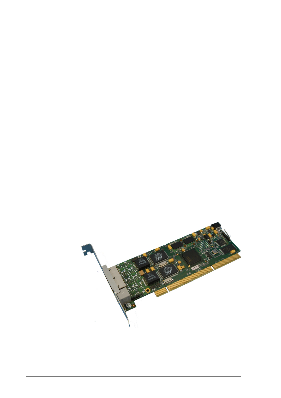
The DAG 3.7GF card is shown below:
Card
Architecture
Overview
The DAG 3.7G series card is designed for packet capture and generation on
Ethernet networks.
Ethernet data is received by a DAG 3.7G series card interfaces, and fed
through framers into the Xilinx FPGA.
This FPGA contains an Ethernet processor and the DUCK timestamp engine.
Because of close association of the components, packets are time-stamped
accurately. Time stamped packet records are stored by the FPGA, which
interfaces to the PCI bus. All packet records are written to host PC memory
during capture operations.
The following diagram shows the card’s major components and the flow data:

EDM01-07: DAG 3.7G Card User Guide
Version 7: May 2006 4 ©2005
NIC Functionality
The DAG 3.7G series card have two 10/100/1000 Mbps Copper Ethernet
There default configuration is as if the DAG card was a NIC, and can be
connected to a hub, switch or router port directly.
Each DAG 3.7G port can also be connected to a NIC card. The DAG 3.7G
cards support automatic MDI/MDI-X switching, so can be connected to a
NIC using either an Ethernet straight-through or cross-over cable. When
using the failsafe feature of the DAG 3.7GF, there are some advantages to
using a straight through cable rather than a cross-over one. The DAG card
captures all packets received on each port, similar to a NIC in promiscuous
mode.
Memory Holes
Memory hole configuration is dependant on the application requirements. For
a receive-only configuration, two memory holes are available, on each port.
For packet forwarding applications, only one memory hole can be utilised.
Failsafe Relays
The DAG 3.7GF card failsafe relays are capable of either:
•Connecting the two ports together as a pass-through link
•Connecting both ports to the FPGA to enable data capture. This feature
is not available on 3.7GP cards.

EDM01-07: DAG 3.7G Card User Guide
©2005 5 Version 7: May 2006
Chapter 2:
Installation
Introduction
Note: Throughout this document the “DAG 3.7G” refers to both the
DAG 3.7GF card and the DAG 3.7GP card.
The DAG 3.7G card can be installed in any free 32-bit or 64-bit Bus
Mastering PCI slot.
Although the driver supports up to four DAG cards by default in one system,
due to bandwidth limitations there should not be more than one card on a
single PCI-bus.
The cards make very heavy use of PCI-bus data transfer resources. This is
not usually a limitation as for most applications a maximum of two cards only
can be used with reasonable application performance.
DAG Device
Driver
The DAG device driver must be installed before you install the DAG card
itself.
If you have not already completed this please follow the instructions in
EDM04-01 Linux FreeBSD Software Installation Guide or EDM 04-02
Windows Software Installation Guide as appropriate, which are
included on the CD shipped with the DAG card.
Inserting the
DAG Card
To insert the DAG card in the PC follow the steps described below:
•Turn power to the computer OFF,
•Remove the PCI bus slot screw and cover,
•Insert DAG card into PCI bus slot ensuring that it is firmly seated in the
slot,
•Check the free end of the card fits securely into the card-end bracket
that supports the weight of the card,
•Secure the card with the bus slot screw,
•Turn power to the computer ON.
Connecting
the Interfaces
There are two RJ45 connectors on the DAG 3.7G card, and a RJ11 connector.
The RJ45 connectors, furthest from PCI connector, are the network
monitoring ports. These can be connected directly to Ethernet Hubs, Switches
or Router ports with a standard Ethernet cable. The monitoring ports can also
be connected directly to NIC cards using either ethernet cross-over or
straight-through cables.
The RJ11 socket, near the PCI connector, is for the time synchronization
input. This socket should never be connected to a telephone line.

EDM01-07: DAG 3.7G Card User Guide
Version 7: May 2006 6 ©2005
Card
Sensitivity
The DAG 3.7G card monitoring ports conform to the IEEE 802.3 standard for
Ethernet.
The standard specifies a maximum cable length of 100 metres for 10Base-T,
100-BaseTX, and 1000Base-T operation over unshielded twisted pair CAT5E
or better cable.
By default DAG 3.7G card automatically detects line speed of 10, 100, or
1000Mbps.
Light link status lights indicate the network is detected correctly.
Activity lights indicate network traffic.
EDM01-07: DAG 3.7G Card User Guide
©2005 7 Version 7: May 2006
Chapter 3:
Configuring the Card
Introduction
Configuring the DAG card for data capture involves:
•Engaging failsafe relays,
•Interpreting card LED status,
•Starting a capture session,
•Inspecting statistics.
Engaging
Failsafe
Relays
The 3.7GF has relays for inline forwarding applications to reconnect the two
ports in case of power failure. When the relays are in this state, the ports are
not connected to the physical layer devices on the card. To use the card in
such case the relays must be engaged. Run:
dagwatchdog -p -d N
Where
N
is the number of the DAG card to engage the relays on.
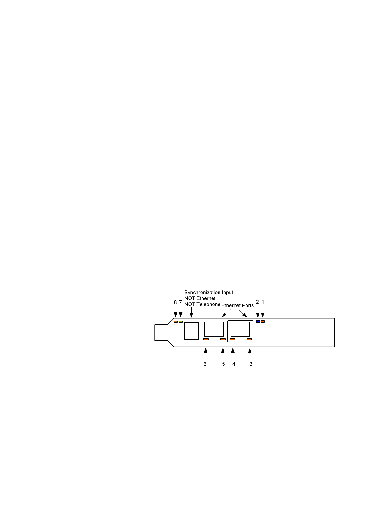
LEDs and
Inputs
Before you begin to configure the DAG card it is important to understand the
function of the various LEDs associated with the card, as well as the sockets
on the PCI bracket.

EDM01-07: DAG 3.7G Card User Guide
Version 7: May 2006 8 ©2005
The LED functions are described next:
LED Description
1 Burst manager run; Indicates card is capturing packets and
transferring them to the host
2 FPGA successfully programmed.
3 Port A Activity
4 Port A Link up
5 Port B Activity
6 Port B Link up
7 PPS In: Pulse Per Second In; Indicates card is receiving an external
clock synchronization signal. Inactive when PPS cable not
plugged in.
8 PPS Out: Pulse Per Second Out; Blinking indicates the card is
sending a clock synchronization signal.
Configuration
Utility
The
dagthree
utility supports configuration and reading of card status and
physical layer interface statistics for the DAG 3.x series of cards. In a
troubleshooting configuration options,
dagthree –si
will display the
operational status of the physical and framing layers, updated once per
second.
More details about the meaning of the various parameters/options are
supplied through the help page (
dagthree –h
) as well as via the manual
page.
Default
Configuration
Before configuring the card for your specific requirements Endace
recommends that you return the card to the default settings using:
dagthree -d1 default
An example dagthree output is shown below:
linkA noreset 10
linkB noreset 10
packetA varlen slen=1536 align64
packetB varlen slen=1536 align64
packetA drop=0
packetB drop=0
rx steer=stream0
tx noifaceswap nooverlap
terf terf_strip32
pci 33MHz 64-bit buf=128MiB rxstreams=2 txstreams=1 mem=56:16:56:0
Firmware: dag37gepci_erf_v2_5 3s1500fg456 2006/03/28 17:07:15 (user)
Card Serial: 4925 MAC Address A: 00:00:00:00:00:00 MAC Address B:
00:00:00:00:00:00 MAC Address C: 00:00:00:00:00:00 MAC Address D:
00:00:00:00:00:00
Note: The above is an example for when
rxmerge
mode is engaged,
and no transmit memory has been allocated. Although it is in
rxmerge
mode, memory has been allocated to the second memory hole. This is
not strictly necessary.

EDM01-07: DAG 3.7G Card User Guide
©2005 9 Version 7: May 2006
Each of the items shown below can be changed
reset
Reset the ethernet framers, set auto mode
default
Initialise the card and set the default settings
auto
Set autonegotiate mode, card will detect rate
10
Force 10BaseT mode, 10Mbps
100
Force 100BaseTX mode, 100Mbp
1000
Force 1000BaseT mode, 1000Mbps
slen=X
Capture X bytes of the packet content
[no]varlen
The card can operate in two modes, variable length capture
(
varlen
), and fixed length capture (
novarlen
).
In variable length capture mode, a maximum capture size is
set with
slen=N
bytes. This figure should be in the range 32
to 9600 and is rounded down to the nearest multiple of 8.
Packets longer than slen are truncated. Packets shorter than
slen will produce shorter records, saving bandwidth and
storage space.
In fixed length mode, packets longer than the selected slen
are truncated to slen, but packets shorter than slen will
produce records that are padded out to the slen length.
Avoid large values of slen in fixed length mode, as short
packets arriving will produce large padded records, wasting
bandwidth and storage space.
rxsplit
Send data from Port A to Stream 0.
Equivalent to Port B = Stream 2
Send data from Port B to Stream 2.
Equivalent to Port B = Stream 2
rxmerge
Send data from Port A to Stream 0.
Send data from Port B to Stream 0.
Equivalent to Port B = Stream 0
Note: You can not change
align64
. This is permanently set.
Example
For instance, if the card is configured with fixed length capture
(
novarlen
)
, but
configuration to variable length capture is wanted, removing or adding the "
no
"
prefix will change the setting
.
Simply type:
dagthree varlen
linkA noreset 10
linkB noreset 10
packetA varlen slen=1536 align64
packetB varlen slen=1536 align64
packetA drop=0
packetB drop=0
rx steer=stream0
tx noifaceswap nooverlap
terf terf_strip32
pci 33MHz 64-bit buf=128MiB rxstreams=2 txstreams=1 mem=56:16:56:0
Firmware: dag37gepci_erf_v2_5 3s1500fg456 2006/03/28 17:07:15 (user) Card
Serial: 4925 MAC Address A: 00:00:00:00:00:00 MAC Address B:
00:00:00:00:00:00 MAC Address C: 00:00:00:00:00:00 MAC Address D:
00:00:00:00:00:00

EDM01-07: DAG 3.7G Card User Guide
Version 7: May 2006 10 ©2005
Interface
Statistics
Overview
When you have configured the card according to your specific requirements you
can view the interface statistics to check the status of each of the links using:
dagthree -d dag0 –si
The tool displays a number of status bits that have occurred since last reading.
The following example shows the interval is set to one second via the
-i
option.
Spd
Link Speed, 10, 100 or 1000 Mbps
Lnk
Link state
FD
Full Duplex
MA
Device is link master
Neg
Auto-negotiation completed (Auto mode only)
RF
Remote Fault Detected Error
JB
Jabber Detected Error
Err
Ethernet Symbol Error Count
Interface
Statistics
(cont.)
Example
The following example is for a card with no valid input:
dagthree -d dag0 –si
Spd Lnk FD Neg JB MA RF Err Spd Lnk FD Neg JB MA RF Err
1000 0 0 0 0 1 1 65535 1000 0 0 0 0 1 1 0
1000 0 0 0 0 1 1 0 1000 0 0 0 0 1 1 0
1000 0 0 0 0 1 1 0 1000 0 0 0 0 1 1 0
The following is an example for a card locked to a 1000Base-T stream:
dagthree -d dag0 –si
Spd Lnk FD Neg JB MA RF Err Spd Lnk FD Neg JB MA RF Err
1000 1 1 1 0 1 0 0 1000 1 1 1 0 0 0 0
1000 1 1 1 0 1 0 0 1000 1 1 1 0 0 0 0
1000 1 1 1 0 1 0 0 1000 1 1 1 0 0 0 0
The following example is for a card locked to a 100base-TX stream:
dagthree -d dag0 –si
Spd Lnk FD Neg JB MA RF Err Spd Lnk FD Neg JB MA RF Err
100 1 1 1 0 1 0 0 100 1 1 1 0 0 0 0
100 1 1 1 0 1 0 0 100 1 1 1 0 0 0 0
100 1 1 1 0 1 0 0 100 1 1 1 0 0 0 0

EDM01-07: DAG 3.7G Card User Guide
©2005 11 Version 7: May 2006
Description The following example is for a card locked to a 10base-T stream:
dagthree -d dag0 –si
Spd Lnk FD Neg JB MA RF Err Spd Lnk FD Neg JB MA RF Err
10 1 1 1 0 1 0 0 10 1 1 1 0 0 0 0
10 1 1 1 0 1 0 0 10 1 1 1 0 0 0 0
10 1 1 1 0 1 0 0 10 1 1 1 0 0 0 0
If the RF or JB bits are
1
's, this indicates a problem with the network link. This
may or may not be related to the configuration of the DAG 3.7G card.
Check all cabling, ensuring that runs are not too long and that plugs are firmly
clipped into their connectors. Check error condition detectors or counters on the
Ethernet equipment.

EDM01-07: DAG 3.7G Card User Guide
Version 7: May 2006 12 ©2005

EDM01-07: DAG 3.7G Card User Guide
©2005 13 Version 7: May 2006
Chapter 4:
Capturing Data
Starting a
Session
For a typical data capture session follow the steps listed below:
•Move to the
dag
directory,
•Load the appropriate driver,
•Then load the appropriate FPGA image
•Set the integrity of the card’s physical layer and check the integrity of the
physical layer to each DAG card. For example:
dagthree –d0 dag0 default
•Engage the failsafe relays using:
dagwatchdog –p –d N
Note: This command is not required on non-failsafe versions of the
card
•Start the capture session using:
dagsnap -d dag0 –v -o tracefile
Note: You can use the
-v
option to provide user information during a
capture session, although you may want to omit it for automated trace
runs.
By default
dagsnap
will run indefinitely but can be stopped using CTRL+C.
You can also configure
dagsnap
to run for a fixed time period then exit.
High Load
Performance
Overview
As the DAG 3.7T card captures packets from the network link, it writes a
record for each packet into a large buffer in the host PC’s main memory.
Avoiding Packet Loss
To avoid packet loss, the user application reading the record, such as
dagsnap
, must be able to read records out of the buffer faster than they
arrive. If not the buffer will eventually fill and packet records will be lost.
If the user process is writing records to hard disk, it may be necessary to use a
faster disk or disk array. If records are being processed in real-time, a faster
host CPU may be required.
In Linux and Free BSD, when the PC buffer fills, the following message
displays on the PC screen:
kernel: dagN: pbm safety net reached 0xNNNNNNNN
The same message is also printed to
log /var/log/messages
. In addition,
when the PC buffer fills the “Data Capture” LED on the card will flash or
flicker, or may go OFF completely.
In Windows no screen message displays to indicate when the buffer is full.
information on detecting buffer overflow and packet loss in Windows.

EDM01-07: DAG 3.7G Card User Guide
Version 7: May 2006 14 ©2005
Detecting Packet Losses
Once the buffer fills, any new packets arriving will be discarded by the DAG
card until some data is read out of the buffer to create free space.
You can detect any such losses by observing the Loss Counter
(lctr
field)
of the Extensible Record Format [ERF]. See Chapter 6: Data Formats later
in this User Guide for more information on the Endace ERF.
Increasing Buffer Size
You can increase the size of the host PC buffer to enable it to cope with
bursts of high traffic load on the network link.
By default the
dagmem
driver reserves 32MB of memory per DAG card in the
system. However if you are capturing at OC-12/STM-4 (622Mbps) rates or
above, you may require a larger buffer.
For Linux/BSD, please refer to the Linux FreeBSD Software Installation
Guide, which is shipped on the installation CD with the DAG3.7T card, for
further information on increasing buffer size.
For Windows the upper limit is 32MB. This is usually sufficient, however if
you do need to increase the amount of reserved memory please contact
The
dsize
option sets the amount of memory used per DAG card in the
system.
Note: For 32-bit Linux kernels, the value of
dsize
multiplied by the
number of DAG cards in the system must be less than the amount of
physical memory installed, as well as less than 890MB.
Packet
Transmission
The firmware included with the DAG 3.7G card allows the DAG to transmit
as well as receive packets, however the DAG does not appear as a network
interface to the operating system.
The following information describes the DAG 3.7G capabilities for
transmitting and receiving packets.
Process Description
Explicit packet
transmission. The DAG will not respond to ARP, ping, or router
discovery protocols. It will only transmit packets
explicitly provided by the user.
This capability allows the DAG card to be used as a
simple traffic load generator.
The DAG can also be used to retransmit previously
recorded packet traces. The packet trace will be
transmitted at 100% line rate, the packet timing of the
original trace file is not reproduced.
This manual suits for next models
2
Table of contents
Other Endace PCI Card manuals


