IM2250A, Page 2
4. Spread the cement with toothpick to form thin, uniform layer covering area of contact, and
immediately position accelerometer on mating surface.
5. Press down and hold accelerometer firmly in place for 30 seconds while cement sets. Allow cement to
set for at least several minutes for maximum strength.
6. If the accelerometer is to operate at low frequencies and/or large acceleration levels, the
accelerometer cable must be secured to the vibrating structure as close as possible to the
accelerometer to avoid cable damage.
Removal Procedure
1. Apply solvent around accelerometer base (side opposite gold lid) with cotton swab and wait a short
period for cement to soften. Repeat the procedure if the solvent evaporates too soon.
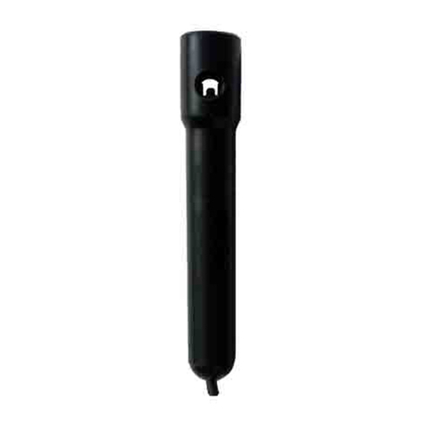
2. Break cement bond, using removal tool P/N 22114 (supplied with the accelerometer). Always use
this tool to remove the Model 2250A Accelerometer from the test structure. Twist or torque the
accelerometer, stressing the bond in shear.
3. Remove cement residue on the accelerometer using a cotton swab dipped in solvent or equivalent
solvent. A short soak will facilitate this process. Repeat, if necessary, to remove all traces of adhesive.
Ensure that all excess adhesive forming fillet around the accelerometer case or built up on the sides of
the accelerometer has been removed.
Failure to heed this caution may prevent proper use of removal tool and result in
damage to the accelerometer.
4. Wipe surfaces clean with cotton swabs or lint-free tissue dipped in solvent.
5. NOTE: The accelerometer base must not be filed, sanded, roughened, or edges burred during
removal of the cement. A rough mounting surface on an accelerometer can result in poor frequency
response and an increase in transverse sensitivity.
Replacement of 3006 Cable Assembly
CAUTION: Do not detach cable from accelerometer while the Model 2250A Accelerometer is exposed
to a dirty or humid environment. Detachment of cable will expose the sensing element
and integral electronics to the atmosphere, and any conducting or solid particles or
moisture entering the accelerometer will result in deterioration of its operation.
Only remove the cable assembly in a clean, dry (<50% RH) atmosphere. Note that the connector has a right-
hand thread. Hold the accelerometer between two fingers. Align the flats on the connector with the open end
of the wrench (P/N 22114, supplied with the accelerometer). Turn cable connector counter clockwise (CCW)
to remove cable assembly.
To install cable assembly, dip the small threaded end of the new cable into the capsule of sealing compound
(supplied). Again, holding the accelerometer with two fingers on one hand, screw the connector into the case
and tighten with the 22114 wrench, using about 1-lbf(~4.5 N) force on the tool. This is approximately a 1 lbf-
in (~0.1 Nm) torque. For most people, the accelerometer will become difficult to hold in the fingers for torque
values greater than 1 lbf-in.
CAUTION: If a vise must be used to hold the accelerometer during attachment of cable, do not apply
excessive clamping force on the unit. It is recommended that the cable connector be
back-threaded before engaging the threads to prevent cross-threading.
WARNING: If the lid came off due to mounting mishap, DO NOT try to repair unit in the field.
Special repair procedure and materials are needed to maintain proper electro-magnetic
shielding of sensing element. Contact the factory whenever repair is required.
