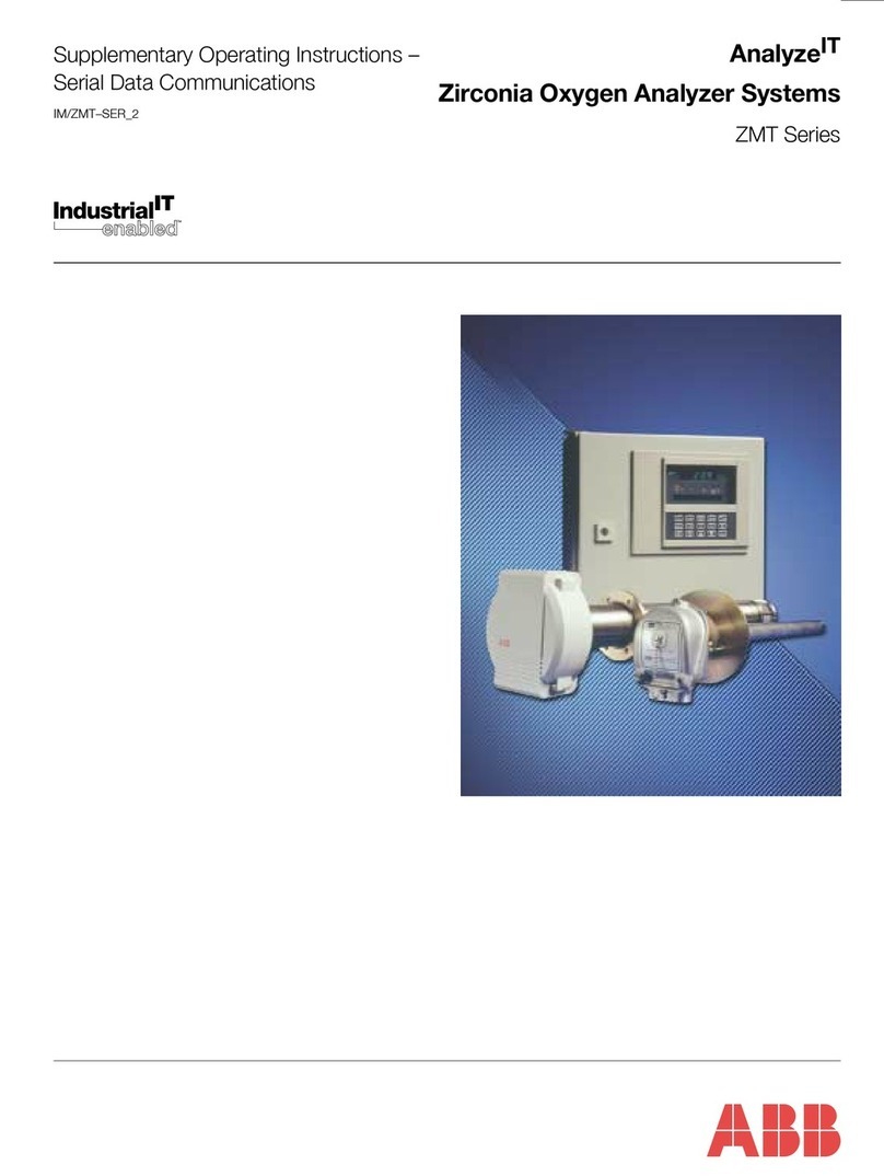
ABB Sensyflow FMT700-P User manual

Operating Instruction
42/14-42-EN
Thermal Mass Flowmete
r
Sensyflow FMT700-P
Pos: 1 /Titelbl ätter / Copyright/BA- IA/Durchfluss/FM T700-P @ 33\mod_1251794739611_3 101.doc @ 298458 @
for air, test benches
Pos: 2 /Titelbl ätter / Copyright/Copy right-Seite @ 32\mod_12477 32119296_3101.doc @ 288410 @

Blinder Text
2 Sensyflow FMT700-P 42/14-42-EN
Thermal Mass Flowmeter
Sensyflow FMT700-P
Operating Instruction
42/14-42-EN
05.2010
Rev. C
Manufacturer:
ABB Automation Products GmbH
Borsigstraße 2
63755 Alzenau
Germany
Tel.: +49 551 905-534
Fax: +49 551 905-555
Customer service center
Phone: +49 180 5 222 580
Fax: +49 621 381 931-29031
© Copyright 2010 by ABB Automation Products GmbH
Subject to changes without notice
This document is protected by copyright. It assists the user in safe and efficient operation of the device.
The contents of this document, whether whole or in part, may not be copied or reproduced without prior
approval by the copyright holder.
Pos: 3 /Inhaltsv erzeichnis/Inhalt sverzeichnis für all e Dokumente @ 0\mod_113871031089 0_3101.doc @ 3129 @
Contents

Contents
42/14-42-EN Sensyflow FMT700-P 3
1Safety.............................................................................................................................................................5
1.1 Intended use...................................................................................................................................................5
1.2 Target groups and qualifications ....................................................................................................................5
1.3 Warranty provisions........................................................................................................................................6
1.4 Note symbols..................................................................................................................................................6
1.5 Name plates ...................................................................................................................................................6
1.6 Safety instructions for electrical installation ...................................................................................................7
1.7 Returning devices...........................................................................................................................................7
1.8 Integrated management system.....................................................................................................................8
1.9 Disposal..........................................................................................................................................................8
1.9.1 Information on WEEE Directive 2002/96/EC (Waste Electrical and Electronic Equipment)...................8
1.9.2 RoHS Directive 2002/95/EC ...................................................................................................................8
2Device description .......................................................................................................................................9
2.1 Front view.......................................................................................................................................................9
2.2 Rear view........................................................................................................................................................9
2.2.1 Supply power ........................................................................................................................................10
2.2.2 D-SUB connector ..................................................................................................................................10
2.2.3 BNC outputs and sensor connection ....................................................................................................11
3Electrical connections ...............................................................................................................................12
3.1 BNC outputs and flowmeter sensor connection...........................................................................................12
3.2 SLOT 1: D-SUB connection „Serial Output“.................................................................................................12
3.3 SLOT 3: D-SUB connection „Totalizer“ ........................................................................................................13
3.4 SLOT 4: D-SUB connection „Analog Outputs“ .............................................................................................14
4Commissioning ..........................................................................................................................................16
5Operation.....................................................................................................................................................17
5.1 Supply / evaluation unit ................................................................................................................................17
5.2 Display unit (Display)....................................................................................................................................18
5.3 Options .........................................................................................................................................................18
5.3.1 Adjustable measuring rate ....................................................................................................................18
5.3.2 Fast measuring rate ..............................................................................................................................19
5.3.3 Analog outputs ......................................................................................................................................20
5.4 Temperature measurement..........................................................................................................................22
5.5 Operation with two flowmeter sensors .........................................................................................................23
6Communication ..........................................................................................................................................24
6.1 Digital interfaces...........................................................................................................................................24
6.1.1 Serial interface ......................................................................................................................................24
6.1.2 Totalizer (integrator function) ................................................................................................................30
7Measuring setup and installation .............................................................................................................33
8Specifications .............................................................................................................................................35
9Dimensions .................................................................................................................................................37
9.1 Flowmeter sensor Sensyflow FMT700-P, DN 25.........................................................................................37
9.2 Flowmeter sensor Sensyflow FMT700-P, DN 50 ... DN 200........................................................................38
9.3 Supply / evaluation unit ................................................................................................................................39
9.4 Accessories ..................................................................................................................................................39
10 Appendix .....................................................................................................................................................46
10.1 Decommissioning and packaging ................................................................................................................46
10.2 Additional documents ...................................................................................................................................46

Contents
4 Sensyflow FMT700-P 42/14-42-EN
10.3 Approvals and certifications .........................................................................................................................46
10.4 Declaration of conformity..............................................................................................................................47
11 Index ............................................................................................................................................................49

Safety
42/14-42-EN Sensyflow FMT700-P 5
Pos: 4.1 /Überschr iften/1/S - U/Sicherhei t@ 0\ mod_1129703894050_3101.doc @ 3168 @ 1
1 Safety
Pos: 4.2 /Sicher heit/Allgemein/A llgemeines und Lesehinweis e @ 37\mod_1267528465562_ 3101.doc @ 325891 @
You must read these instructions carefully prior to installing and commissioning the device.
These instructions are an important part of the product and must be kept for future reference.
These instructions are intended as an overview and do not contain detailed information on all
designs for this product or every possible aspect of installation, operation and maintenance.
For additional information or if specific problems occur that are not discussed in these
instructions, contact the manufacturer.
The content of these instructions is neither part of any previous or existing agreement, promise
or legal relationship nor is it intended to change the same.
This product is built based on state-of-the-art technology and is operationally safe. It has been
tested and left the factory in perfect working order from a safety perspective. The information in
the manual must be observed and followed in order to maintain this state throughout the period
of operation.
Modifications and repairs to the product may only be performed if expressly permitted by these
instructions.
Only by observing all of the safety instructions and all safety/warning symbols in these
instructions can optimum protection of both personnel and the environment, as well as safe and
fault-free operation of the device, be ensured.
Information and symbols directly on the product must be observed. They may not be removed
and must be fully legible at all times.
Pos: 4.3 /Übersc hriften/1.1/1-spal tig/A - C/Bestimmungs gemäße Verwendung @ 1\mod_11476 75805609_3101.doc @ 10755 @ 2
1.1 Intended use
Pos: 4.4 /Sicher heit/Durchfluss/FM T700-P/Bestimmungs gemäße Verwendung (FMT700-P) @ 34\mod_1255518326656_3 101.doc @ 305141 @
Mass flow measurement of air in closed pipelines.
The device is designed for use exclusively within the values stated on the name plate and in the
technical specifications (see the section titled "Specifications").
Pos: 4.5 /Überschr iften/1.1/1-spal tig/V - Z/Zielgruppen und Qual ifikationen @ 22\m od_1222689902850_3101.doc @ 219227 @ 2
1.2 Target groups and qualifications
Pos: 4.6 /Sicher heit/Durchfluss/FMT700- P/Zielgruppen und Quali fikationen (FM T700-P) @ 34\mod_12555185217 03_3101.doc @ 305165 @
Installation, commissioning, and maintenance of the product may only be performed by trained
specialist personnel who have been authorized by the plant operator accordingly. The specialist
personnel must have read and understood the manual and must comply with its instructions.
The operating company must strictly observe the applicable national regulations relating to the
installation, function testing, repair, and maintenance of electrical products.
Pos: 4.7 /======= Seitenumbruch ========@ 0\mod_112653236 5768_3101.doc @ 3830 @

Safety
6 Sensyflow FMT700-P 42/14-42-EN
Pos: 4.8 /Sicher heit/Allgemein/G ewährleistungsbesti mmungen @ 0\mod_1129706207246 _3101.doc @ 3261 @ 2
1.3 Warranty provisions
Using the device in a manner that does not fall within the scope of its intended use, disregarding
this instruction, using underqualified personnel, or making unauthorized alterations releases the
manufacturer from liability for any resulting damage. This renders the manufacturer's warranty
null and void.
Pos: 4.9 /Übersc hriften/1.1/1-spal tig/G - I/Hinweissym bole @ 34\mod_1255520390015_310 1.doc @ 305237 @ 2
1.4 Note symbols
Pos: 4.10 /Sicher heit/Durchfluss /FMT700-P/Hinweissy mbole @ 34\mod_1255518666312_3 101.doc @ 305189 @
IMPORTANT (NOTICE)
This symbol indicates operator tips, particularly useful information, or important information
about the product or its further uses. It does not indicate a dangerous or damaging situation.
Pos: 4.11 /Übersc hriften/1.1/1-spal tig/S - U/Typenschi lder @ 27\mod_1238658820750_31 01.doc @ 254755 @ 2
1.5 Name plates
Pos: 4.12 /Sicher heit/Durchfluss/ FMT700-P/Typenschi ld FMT700-P @ 34\mod_125551982307 8_3101.doc @ 305213 @
G00974
Sensyflow FMT700-P
max. power: 45 W
interface: V.24
2nd unit:
type no.: 14243 - 111101 - 411
[x]230V[]115VAC50-60Hz
serial no.: 9999
Made in Germany ABB, 63755 Alzenau
11
3
2
1
4
5
6
7
8
9
10
Fig. 1
1 Device manufacturer
2 Order code
3 Serial number
4 Permissible supply power, frequency
5 Maximum power consumption
6 Interface
7 1st or 2nd flowmeter sensor
8 CE mark (EC conformity)
9 Model name
10 Refer to product documentation
11 Country of manufacture
Pos: 4.13/======= Seitenumbruch ======== @ 0\mod_1126532365768_3 101.doc @ 3830 @

Safety
42/14-42-EN Sensyflow FMT700-P 7
Pos: 4.14 /Sicher heit/Durchfluss /Allgemein/Sicher heitshinweise zur elekt rischen Installat ion (Durchfluss) @ 0\m od_1129733762419_3101. doc @ 3267 @ 2
1.6 Safety instructions for electrical installation
The electrical connection may only be made by authorized specialist personnel according to the
electrical plans.
The electrical connection information in the manual must be observed; otherwise, the electrical
protection type may be adversely affected.
Ground the measurement system according to requirements.
Pos: 4.15 /Sicher heit/Durchfluss /FMT500-IG/Rücksendung v on Geräten (Therm. Mass e-Durchflussmesser ) @ 27\mod_1240227589937_3 101.doc @ 260031 @ 2
1.7 Returning devices
Use the original packaging or a secure transport container of an appropriate type if you need to
return the device for repair or recalibration purposes. Fill out the return form (see the Appendix)
and include this with the device.
The EU Directive governing hazardous materials dictates that the owners of any hazardous
waste are also responsible for disposing of it.
All devices delivered to the manufacturer must be free from any hazardous materials (acids,
alkalis, solvents, etc.).
Pipe components and flowmeter sensors contain hollow spaces. If they have been used in
conjunction with hazardous materials, they must therefore be rinsed out in order to neutralize
any such substances.
The owner will be charged for any costs incurred as a result of the device not having been
adequately cleaned or of any failure to dispose of hazardous materials. The manufacturer
reserves the right to return a contaminated device.
Pos: 4.16 /Sicher heit/Allgemein/A dresse für Rücksendung (Temper atur und TM-Durc hflussmesser) @ 32\mod_124773 7276859_3101.doc @ 288547 @
Please
Please contact Customer Center Service acc. to page 2 for nearest service location.
Pos: 4.17/======= Seitenumbruch ======== @ 0\mod_1126532365768_3 101.doc @ 3830 @

Safety
8 Sensyflow FMT700-P 42/14-42-EN
Pos: 4.18 /Übersc hriften/1.1/1-spal tig/G - I/Integri ertes Management-Syst em @ 34\mod_1259134994906_31 01.doc @ 309775 @ 2
1.8 Integrated management system
Pos: 4.19 /Sicher heit/Allgemein/I ntegriertes Management- System @ 34\mod_12591346474 37_3101.doc @ 309751 @
ABB Automation Products GmbH operates an integrated management system, consisting of:
• Quality management system to ISO 9001:2008
• Environmental management system to ISO 14001:2004
• Occupational health and safety management system to BS OHSAS 18001:2007 and
• Data and information protection management system
Environmental awareness is an important part of our company policy.
Our products and solutions are intended to have a minimal impact on the environment and on
people during manufacturing, storage, transport, use, and disposal.
This includes the environmentally-friendly use of natural resources. We conducts an open
dialog with the public through our publications.
Pos: 4.20 /Übersc hriften/1.1/1-spal tig/D - F/Entsor gung @ 1\mod_1147936854359_3101. doc @ 12703 @ 2
1.9 Disposal
Pos: 4.21 /Sicher heit/Allgemein/E ntsorgung @ 34\mod_12591319307 96_3101.doc @ 309722 @ 33
This product is manufactured from materials that can be reused by specialist recycling
companies.
1.9.1 Information on WEEE Directive 2002/96/EC (Waste Electrical and Electronic Equipment)
This product is not subject to WEEE Directive 2002/96/EC or relevant national laws
(e.g., ElektroG in Germany).
The product must be disposed of at a specialist recycling facility. Do not use municipal garbage
collection points. According to the WEEE Directive 2002/96/EC, only products used in private
applications may be disposed of at municipal garbage facilities. Proper disposal prevents
negative effects on people and the environment, and supports the reuse of valuable raw
materials.
If it is not possible to dispose of old equipment properly, ABB Service can accept and dispose of
returns for a fee.
1.9.2 RoHS Directive 2002/95/EC
With the Electrical and Electronic Equipment Act (ElektroG) in Germany, the European
Directives 2002/96/EC (WEEE) and 2002/95/EC (RoHS) are translated into national law.
ElektroG defines the products that are subject to regulated collection and disposal or reuse in
the event of disposal or at the end of their service life. ElektroG also prohibits the marketing of
electrical and electronic equipment that contains certain amounts of lead, cadmium, mercury,
hexavalent chromium, polybrominated biphenyls (PBB), and polybrominated diphenyl ethers
(PBDE) (also known as hazardous substances with restricted uses).
The products provided by ABB Automation Products GmbH do not fall within the current scope
of the directive on waste from electrical and electronic equipment according to ElektroG. If the
necessary components are available on the market at the right time, in the future these
substances will no longer be used in new product development.
Pos: 5 /======= Seitenumbruc h ========@ 0\mod_112653236576 8_3101.doc @ 3830 @

Device description
42/14-42-EN Sensyflow FMT700-P 9
Pos: 6.1 /Übersc hriften/1/G - I/Gerät ebeschreibung @ 33\mod_12530 19537999_3101.doc @ 300791 @ 1
2 Device description
Pos: 6.2 /Aufbau und Funkt ion/Durchfl uss/FMT700-P/Frontans icht @ 33\mod_125309198368 7_3101.doc @ 301012 @ 2
2.1 Front view
G00982
1
2
3
Fig. 2
12 Display
13 Measuring rate
14 Selection buttons
TEMP
RESET
SAMPLE RATE
UNIT SELECT
SENSOR SELECT
For selecting the fluid temperature
For performing a master reset
Switch for setting the measuring rate
For switching over to the 2nd display unit
For switching the flowmeter sensors (meter tubes) over
Pos: 6.3 /Aufbau und Funkt ion/Durchfl uss/FMT700-P/Rückans icht @ 33\mod_1253095059359_31 01.doc @ 301036 @ 2
2.2 Rear view
G00931
Fig. 3
Pos: 6.4 /======= Seitenumbruch ========@ 0\mod_112653236 5768_3101.doc @ 3830 @

Device description
10 Sensyflow FMT700-P 42/14-42-EN
Pos: 6.5 /Aufbau und Funkt ion/Durchfl uss/FMT700-P/Energiev ersorgung @ 33\mod_12530986 44296_3101.doc @ 301084 @ 3
2.2.1 Supply power
Master On / Off switch
Fuse slot
Socket for 3-pin power plug with internal fuse
(see note on rear)
Notice - Potential damage to
parts!
Check whether the voltage
specified on the name plate
matches the line voltage.
G00932
Fig. 4
Pos: 6.6 /Aufbau und Funkt ion/Durchfl uss/FMT700-P/D-SUB- Stecker @ 33\mod_1253098715406_3 101.doc @ 301108 @ 3
2.2.2 D-SUB connector
SLOT 1
25-pin D-SUB connector: "Serial output"
SLOT 3
25-pin D-SUB connector: "Totalizer"
SLOT 4
25-pin D-SUB connector "Analog outputs"
G00933
Fig. 5
Pos: 6.7 /======= Seitenumbruch ========@ 0\mod_112653236 5768_3101.doc @ 3830 @

Device description
42/14-42-EN Sensyflow FMT700-P 11
Pos: 6.8 /Aufbau und Funkt ion/Durchfl uss/FMT700-P/BNC-Aus gänge und Sensoranschluss @ 33\mod_1253098804687_31 01.doc @ 301132 @ 3
2.2.3 BNC outputs and sensor connection
ANALOG OUT 0 ... 10 V
Analog output voltage via BNC socket
ANALOG OUT 0 (4) ... 20 mA
Analog output current via BNC socket
SENSOR 1
Connection for flowmeter sensor 1 (7-pin)
SENSOR 2
Connection for flowmeter sensor
2 (7-pin) for operation with 2 flowmeter
sensors
G00934
Fig. 6
Pos: 7 /======= Seitenumbruc h ========@ 0\mod_112653236576 8_3101.doc @ 3830 @

Electrical connections
12 Sensyflow FMT700-P 42/14-42-EN
Pos: 8.1 /Überschr iften/1/D - F/Elektr ische Anschlüsse @ 7\mod_114837 1845359_3101.doc @ 13273 @ 11
3 Electrical connections
Pos: 8.2 /Technisc he Daten / Datenblatt/ Durchfluss/FMT700-P/ Elektrischer Ansc hluss/BNC-Ausgänge @ 33\mod_12 51812161814_3101. doc @ 298654 @ 2
3.1 BNC outputs and flowmeter sensor connection
BNC outputs
Current output: 0 (4) ... 20 mA
Voltage output: 0 ... 10 V
G00923
Flowmeter sensor connection
1 = Temperature signal
2 = Flow signal
3 = Supply voltage (+ 18 V)
4 = Flowmeter sensor coding 20
5 = Flowmeter sensor coding 21
6 = Flowmeter sensor coding 22
7 = Flowmeter sensor coding 23
G00924
Fig. 7: Terminal connection of BNC socket and flowmeter sensor socket
Pos: 8.3 /==== Leeres Modul mit einer Absatzmark e, DS, 1-spaltig ==== @ 2\mod_1153381574375_0.doc @ 35553 @
Pos: 8.4 /Technisc he Daten / Datenblatt/ Durchfluss/FMT700-P/ Elektrischer Ansc hluss/SLOT 1: D-SUB-St ecker „Serieller Ausgang“ @ 33\mod_1251812620955_3101. doc @ 298678 @ 2
3.2 SLOT 1: D-SUB connection „Serial Output“
Pin Assignment Pin Assignment
1 - 14 -
2 TxD Transmi data 15 -
3 RxD Receive data 16 -
4 - 17 -
5 - 18 -
6 - 19 -
7 GND 20 -
8 - 21 -
9 - 22 -
10 - 23 -
11 - 24 -
12 - 25 -
13 -
G00925
25
14
13
1
Fig. 8: Terminal connection of 25-pole D-SUB connection „Serial Output”
Pos: 8.5 /======= Seitenumbruch ========@ 0\mod_112653236 5768_3101.doc @ 3830 @

Electrical connections
42/14-42-EN Sensyflow FMT700-P 13
Pos: 8.6 /Technisc he Daten / Datenblatt/ Durchfluss/FMT700-P/ Elektrischer Ansc hluss/SLOT 3: D-SUB-St ecker „Summierende Mess ung“@ 33\mod_1251878224783_3 101.doc @ 298735 @ 2
3.3 SLOT 3: D-SUB connection „Totalizer“
Pin Assignment Pin Assignment
1 20LSB1) 14 213
2 2115 214 MSB2)
3 2216
4 2317
5 2418
6 2519
7 2620
8 2721
9 2822
10 2923 REMOTE-CTRLSTART/STOP
11 210 24 Uext.
12 211 25 GNDext.
13 212 1) LSB = Least Significant Bit
2) MSB = Most Significat Bit
G00925
25
14
13
1
Fig. 9: Terminal connection of 25-pole D-SUB connection „Totalizer”
Sensyflow FMT700-P User
G00927
R
L
U
ext.
REMOTE
CTRL
DATA +
DATA-READY
Fig. 10: Terminal connection of inputs / outputs
Pos: 8.7 /======= Seitenumbruch ========@ 0\mod_112653236 5768_3101.doc @ 3830 @

Electrical connections
14 Sensyflow FMT700-P 42/14-42-EN
Pos: 8.8 /Technisc he Daten / Datenblatt/ Durchfluss/FMT700-P/ Elektrischer Ansc hluss/SLOT 4: D-SUB-St ecker „Analogausgänge“ @ 33\ mod_1251878296252_310 1.doc @ 298759 @ 2
3.4 SLOT 4: D-SUB connection „Analog Outputs“
Pin Assignment Pin Assignment
1 GND 14
Iout GND
2 Iout+ 15 Uout GND
3 Uout+ 16 GND
4 Flowmeter sensor coding 17 Flowmeter sensor coding
5 Nominal diameter coding 18 Nominal diameter coding
6 Nominal diameter coding 19 Nominal diameter coding
7 Free coding 20 Free coding
8 Free coding 21 Free coding
9 - 22 -
10 - 23 -
11 Temp. 1 + 24 Temp. 1 -
12 Temp. 2 + 25 Temp. 2 -
13 GNDext.
G00925
25
14
13
1
Fig. 11: Terminal connection of 25-pole D-SUB connection „Analog Outputs”
Digital coding of the flowmeter sensor
Sensyflow FMT700-P User
The outputs are connected as „open collectors“.
Technical data
Collector-emitter-voltage 5 ... 24 V DC
Load resistance RLmin. 2 kΩ
Log. level 0 = Uext.
Log. level 1 = e. g. approx. 0.8 V
(at+15VU
ext.; negative logic)
G00926
R
L
R
L
R
L
Bit 1
Bit 2
Bit 3
Uext.
R2k
U =5...24VDC
L
ext.
?W
GNDext.
Fig. 12: Terminal connection of open-collector outputs for flowmeter sensor coding

Electrical connections
42/14-42-EN Sensyflow FMT700-P 15
Nominal diameter coding
Pin 5 Pin 18 Pin 6 Pin 19 Hex
No measuring tube 0 0 0 0 00
DN 25 1 1 0 0 30
DN 50 1 0 1 0 50
DN 80 1 1 1 0 70
DN 100 1 0 0 1 90
DN 150 1 1 0 1 B0
DN 200 1 0 1 1 D0
Special 1 1 1 1 F0
Pin 4 Pin 17
Flowmeter sensor 1 1 1
Flowmeter sensor 2 1 0
Medium temperature flowmeter sensor 1 0 1
Medium temperature flowmeter sensor 2 0 0
Pos: 9 /======= Seitenumbruc h ========@ 0\mod_112653236576 8_3101.doc @ 3830 @

Commissioning
16 Sensyflow FMT700-P 42/14-42-EN
Pos: 10 /Übersc hriften/1/G - I/Inbetr iebnahme @ 0\mod_1131980668835 _3101.doc @ 3150 @ 11
4 Commissioning
Pos: 11 /Inbetri ebnahme/Durchfluss/ FMT700-P/Inbetri ebnahme @ 33\mod_1253104112968_ 3101.doc @ 301157 @
1. Fit the flowmeter sensor in the measuring section. Ensure that the tapered flange connection
is secure (tightness) and observe the flow direction (direction indicated by arrow).
2. Connect the flowmeter sensor and supply / evaluation unit using the flowmeter sensor cable
(7-pin).
3. Use the power cable supplied to connect the supply / evaluation unit to the permissible
supply voltage.
4. Switch on the measuring system using the master On / Off switch.
Important
Before the device switches to the actual measuring mode, it performs a self-test, during which
all the indicators on the "DISPLAY" light up. After a minute, the device is ready for operation. It
then takes approximately half an hour to reach maximum measuring accuracy.
The measuring rate is set to N = 100. If you require a different measuring rate (option), please
refer to section 5.3.1.
Whenever communication between the flowmeter sensor and supply / evaluation unit is
interrupted, e.g., after the flowmeter sensor has been changed, you must remember to press
the "RESET" button.
If no flowmeter sensor is connected, the "EO2" error message appears to indicate this.
If the "E11" error message appears, it means that you have either pressed the "TEMP" button
when there is no temperature sensor with a temperature option or that an error has occurred
in the temperature evaluation system.
Pos: 12 /======= Seitenumbruch ======== @ 0\mod_11265323657 68_3101.doc @ 3830 @

Operation
42/14-42-EN Sensyflow FMT700-P 17
Pos: 13.1 /Übersc hriften/1/A - C/Bedi enung @ 1\mod_1144675546171_31 01.doc @ 5944 @ 11
5 Operation
Pos: 13.2 /Übersc hriften/1.1/1-spal tig/S - U/Speise- / Ausw ertegerät @ 33\mod_12507572 68125_3101.doc @ 294159 @ 2
5.1 Supply / evaluation unit
Pos: 13.3 /Bedienung/Dur chfluss/FMT700-P/Spei se- / Auswertegerät @ 33\mod_1253178952406_3 101.doc @ 301991 @
The supply / evaluation unit involves the use of microprocessor technology. The transmitter
signal is linearized and shown directly as a mass or standard volume flow value (e.g., in kg/h or
m3N/h)
Thanks to the microprocessor, one supply / evaluation unit can cater for all flowmeter sensor
nominal diameters with a standard measuring range. It also makes for user-friendly operation.
The device is available as a 19" plug-in module or as a portable desktop unit for a variety of
supply voltages (see the section titled "Specifications").
G00935
Fig. 13: Supply / evaluation unit as a portable desktop unit
The measuring range of the relevant transmitter is detected automatically when the flowmeter
sensor is connected. Measuring range detection has to be performed if there are two flowmeter
sensors connected (see section 5.5) and if the measuring signal is to undergo downstream
processing in analog format. This measuring range assignment is available at the "analog
outputs" socket as a binary code (see section 3.4).
Pos: 13.4/======= Seitenumbruch ======== @ 0\mod_1126532365768_3 101.doc @ 3830 @

Operation
18 Sensyflow FMT700-P 42/14-42-EN
Pos: 13.5 /Bedienung/ Durchfluss/FMT700- P/Anzeigeeinheit (Display) @ 33\mod_12531679 16609_3101.doc @ 301475 @ 2
5.2 Display unit (Display)
G00936
Fig. 14: Display of the supply / evaluation unit (lamp test during switch-on)
The largest display value supported by the six-digit digital display is 999999.
The units for the measured value indicated appear on the right next to the digital display. The
default unit is kg/h. Other units are also supported.
"SENSOR 1" appears when transmitter 1 is selected.
"SENSOR 2" appears when transmitter 2 is selected (see section 5.5).
"TEMP 1" appears when the temperature of the fluid in transmitter 1 is requested.
"TEMP 2" appears when the temperature of the fluid in transmitter 2 is requested (see section
5.4).
"R.C. REMOTE-CTRL" appears when the device is in "Totalizer" mode (see section 6.1.2).
Pos: 13.6 /Übersc hriften/1.1/1-spal tig/M - O/Optionen @ 33\ mod_1253168019796_3101.d oc @ 301499 @ 2
5.3 Options
Pos: 13.7 /Bedienung/ Durchfluss/FMT 700-P/Einstellbar e Messrate @ 33\mod_1253168086 968_3101.doc @ 301523 @ 3
5.3.1 Adjustable measuring rate
It is often useful to produce an average from the configurable number of individual
measurements. You can set the required number of individual measurements using the selector
switch on the front of the supply / evaluation unit.
A measuring cycle period (time for an individual measurement) lasts approximately
3 milliseconds. The average value calculated for the number of individual measurements
configured is displayed and made available at the interfaces. In standard mode (i.e., when the
device is switched on/before the set measuring rate is adopted), the device automatically
generates an average value from 100 individual measurements.
If the device generates an average value from fewer than 100 individual measurements, the set
measuring rate is used for the analog outputs and the 12-bit parallel interface.
However, the digital display and the serial interface still contain measured values
reflecting an average value for 100 individual measurements.
Proceed as follows to set a measuring rate:
1. Set the required measuring rate using the selector switch on the front of the
supply / evaluation unit.
2. Press the "SAMPLE RATE" button to accept the set measuring rate. The selected measuring
rate appears briefly in the display field as an acknowledgment signal. The measured value
that appears after that is the first of the average values to be calculated from the newly
configured number N.

Operation
42/14-42-EN Sensyflow FMT700-P 19
Important (Notice)
Whenever the measuring system is switched on or after a reset, the device adopts a
measuring rate of N = 100 as soon as the internal test routines have been completed.
Example:
The average mass flowrate needs to be determined using an interval of 3 seconds.
What measuring rate should be set?
3 s = 3,000 ms
N = 1 = 3 ms
Presetting counter setting
= T
= I
= N
Required interval
Duration of a single measurement
No. of individual measurements
1000
3
3000I
T
N
Thus, the measuring rate should be set to N = 1,000 on the switch.
This means that the four-digit switch can be used to produce an average value for the mass
flowrate based on up to 9,999 individual measurements.
When a measuring rate of "0000" is selected, the measuring cycle period is just 1 millisecond
(see section 5.3.2).
To summarize:
• If a low measuring rate is set, the average is produced from a small number of individual
measurements and it is possible to measure and record dynamic processes.
• If a high measuring rate is set, the average is produced from a large number of individual
measurements and undesirable fluctuations can be eliminated.
Pos: 13.8 /Bedienung/ Durchfluss/FMT 700-P/Schnelle Mess rate @ 33\mod_1253168198265_ 3101.doc @ 301547 @ 3
5.3.2 Fast measuring rate
This operating mode is for measuring very fast, dynamic processes. The measuring cycle
period is 1 ms, i.e., an updated measured value is made available at the analog outputs and at
the 12-bit parallel interface once every millisecond.
Proceed as follows to set this operating mode:
• Set the measuring rate to "0000" using the switch on the front of the supply / evaluation unit.
• Press the "SAMPLE RATE" button to accept this measuring rate. "_ _ _ _ _ _ " appears
on the display along with "FAST MODE".
Important (Notice)
If you want the device to revert to the default setting (N = 100), you need to reset it (press
RESET button) or restart it completely.
As soon as the internal test routines have been completed (during which all the indicators light
up), the measuring system starts taking measurements using the default measuring rate
setting of N = 100 again.
Pos: 13.9/======= Seitenumbruch ======== @ 0\mod_1126532365768_3 101.doc @ 3830 @

Operation
20 Sensyflow FMT700-P 42/14-42-EN
Pos: 13.10 /Bedienung/ Durchfluss/ FMT700-P/Analogausgänge @ 33\ mod_1253185794484_310 1.doc @ 302015 @ 3
5.3.3 Analog outputs
The following 3 analog outputs are available as options:
0 ... 10 V
0 ... 20 mA
4 ... 20 mA
The previously set measuring rate (see section 5.3.1) is used for the analog interfaces.
Additional signal-processing units can be connected to the analog outputs, e.g.:
• A recorder
• An oscilloscope
• A transient recorder
• A process computer
• A controller
This makes it possible to visualize and record rapidly changing flowrates.
The Sensyflow FMT700-P measuring system has been specially developed for applications that
call for a rapid response time where changes in flowrate are concerned. Fig. 15 illustrates the
high speed of the measuring signal response when a throttle valve opens compared with the
sluggish behavior associated with a orifice plate.
Sensyflow FMT700-P
G00937
1
2
0,1 s
Time →
Fig. 15: Dynamic measurement: Comparison of Sensyflow FMT700-P and orifice plate in
terms of response time
1 Orifice plate
2 Position of throttle valve
Table of contents
Other ABB Measuring Instrument manuals

ABB
ABB ReliaGear ASPMETER A 42 Installation and operation manual

ABB
ABB AX413 User manual

ABB
ABB CoriolisMaster FCB100 User manual

ABB
ABB PointMaster 200 Series User manual

ABB
ABB FEX300 Operation instructions

ABB
ABB EV1 User manual

ABB
ABB AX400 Series User manual

ABB
ABB LWT300 series User manual

ABB
ABB Totalflow G5 Series User guide

ABB
ABB CoriolisMaster FCM2000 Training manual

ABB
ABB ICOS GLA151 Series User manual

ABB
ABB XRC G5 User manual

ABB
ABB LGR GLA351 Series User manual

ABB
ABB AquaMaster IM9 User manual

ABB
ABB ADS420 User manual

ABB
ABB VLMD-1-2 User manual

ABB
ABB Nitrate 8236 User manual

ABB
ABB Advance Optima Caldos 15-Ex User manual

ABB
ABB COPA-XE Training manual

ABB
ABB TTF200 User manual