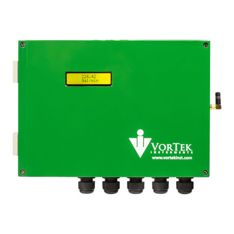
VorTek U44 Series User manual

Series U44 Instruction Manual
M-000-00090 1
VorTek Series U44
Ultrasonic Flow Meter
Instruction Manual
M-000-00090
Rev 8/2021
8475 W I-25 Frontage Rd
Suite 300
Longmont, CO 80504
(303) 682-9999 (888) 386-7835 Fax (303) 682-4368
http://www.vortekinst.com

Series U44 Instruction Manual
M-000-00090 2
Notice
Thank you for choosing our Ultrasonic Flow Meter.
Please read the instruction manual carefully before you use the flow meter to avoid damaging the flow meter or
improper use.
Warning
May cause injury.
Attention
May damage the flow meter.
Some of the instructions may be different for the flow meter you purchased, depending on the configuration
requirements. Otherwise, there is no indication about the product design and upgrade requirements in the
instructions. Please refer to the version number as well as the Appendices.

Series U44 Instruction Manual
M-000-00090 3
Product Components
Be sure to inspect all product components before installing the flow meter. Check to see if the spare parts are in
accordance with the packing list. Make sure that there is no damage to the enclosure due to a loose screw or wire or
other damage that may have occurred during transportation. If you have any questions, please contact your
representative immediately.
Accessories
1. Carrying Case
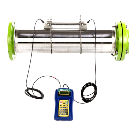
2. Handheld Transmitter
3. Transducers (Pair)
4. Transducer Mounting Bracket
5. Transducer Mounting Bracket Pipe Straps (Pair)
6. Acoustic Coupling Grease
7. Battery Charger
8. Output Cable
9. Measuring Tape

Series U44 Instruction Manual
M-000-00090 4
Table of Contents
1. Product Overview.......................................................................................................................................7
1.1 Introduction ........................................................................................................................................7
1.2 Features of the Ultrasonic Flow Meter...............................................................................................7
1.3 Theory of Operation ...........................................................................................................................7
1.4 Applications........................................................................................................................................8
1.5 U44 Specifications..............................................................................................................................8
2. Installation................................................................................................................................................10
2.1 Wire Connections.............................................................................................................................10
2.1.1 U44 Connections ......................................................................................................................10
2.1.2 Breakout Box Connections.......................................................................................................10
2.2 Powering On.....................................................................................................................................11
2.3 Clamp-On Transducer Installation ...................................................................................................11
2.3.1 Measurement Site Selection .....................................................................................................11
2.3.2 Transducer Spacing ..................................................................................................................12
2.3.3 Transducer Mounting Method..................................................................................................12
2.3.4 V Method..................................................................................................................................13
2.3.5 W Method.................................................................................................................................14
2.3.6 Z Method ..................................................................................................................................15
2.4 Insertion Transducer Installation......................................................................................................15
2.4.1 Measurement Site Selection .....................................................................................................16
2.4.2 Transducer Mounting Instructions............................................................................................17
2.4.3 V Method..................................................................................................................................18
2.4.4 Z Method ..................................................................................................................................18
2.5 Transducer Mounting Inspection......................................................................................................18
2.5.1 Signal Strength .........................................................................................................................18
2.5.2 Signal Quality (Q Value)..........................................................................................................19
2.5.3 Total Time and Delta Time.......................................................................................................19
2.5.4 Transit Time Ratio....................................................................................................................19
2.5.5 Warnings...................................................................................................................................19
3. Display & Menus......................................................................................................................................21
3.1 Display & Keypad............................................................................................................................21
3.1.1 Keypad Functions.....................................................................................................................21
3.1.2 Keypad Operation.....................................................................................................................21

Series U44 Instruction Manual
M-000-00090 5
3.2 Using the Setup Menus.....................................................................................................................22
3.2.1 Programming the Flow Meter...................................................................................................23
3.2.2 Output Menu.............................................................................................................................23
3.2.3 Display Menu ...........................................................................................................................24
3.2.4 Totalizer #1 Menu ....................................................................................................................24
3.2.5 Totalizer #2 Menu ....................................................................................................................25
3.2.6 Energy Menu ............................................................................................................................25
3.2.7 Fluid Menu ...............................................................................................................................26
3.2.8 Units Menu...............................................................................................................................26
3.2.9 Time & Date Menu...................................................................................................................27
3.2.10 Diagnostics Menu.....................................................................................................................27
3.2.11 Calibration Menu......................................................................................................................28
3.2.12 Password Menu.........................................................................................................................28
3.2.13 Engineer Menu .........................................................................................................................29
3.2.14 Engineer Menu 2 ......................................................................................................................30
4. Operation Instructions ..............................................................................................................................31
4.1 System Normal Identification...........................................................................................................31
4.2 Low Velocity Cutoff Value..............................................................................................................31
4.3 Zero Point Settings ...........................................................................................................................31
4.4 Scale Factor ......................................................................................................................................31
4.5 System Lock.....................................................................................................................................32
4.6 Active 4 - 20 mA Current Loop Output............................................................................................32
4.7 Frequency Output.............................................................................................................................32
4.8 Totalizer Pulse Output......................................................................................................................33
4.9 Active 4 - 20 mA Analog Output Calibration ..................................................................................33
4.10 SD Card Operation ...........................................................................................................................34
4.10.1 Specifications............................................................................................................................34
4.10.2 Install or Remove the SD Card While the Meter is Powered On .............................................34
4.11 Serial Number...................................................................................................................................34
5. Troubleshooting........................................................................................................................................35
6. Appendix 1 –Serial Interface Network Use and Communications Protocol ...........................................38
6.1 Overview ..........................................................................................................................................38
6.2 Connection via RS-485 to the Host Device......................................................................................38
6.3 Modbus Communications Protocol and Use ....................................................................................38

Series U44 Instruction Manual
M-000-00090 6
6.3.1 HL Protocol ..............................................................................................................................38
6.3.2 Modbus Protocol.......................................................................................................................40
7. Appendix 2 –Flow Application Data.......................................................................................................45
7.1 Sound Velocity and Viscosity for Fluids Commonly Used..............................................................45
7.2 Sound Velocity for Various Materials Commonly Used..................................................................45
7.3 Sound Velocity in Water (1 atm) at Different Temperatures ...........................................................46

Series U44 Instruction Manual
M-000-00090 7
1. Product Overview
1.1 Introduction
This product is a portable, clamp-on type ultrasonic flow meter using transfer time technology. The clamp-on
type ultrasonic flow meter is easy to attach and has no need to cut off the pipe, which saves you a lot of
trouble and cost. At the same time, this flow meter has our unique calculation software to ensure high
accuracy and low velocity response.
This ultrasonic flow meter is applicable to the oil industry, water treatment, pure water, chemical, etc.
The ultrasonic flow meter could add an RTD model and temperature sensor to become an energy meter for
the monitoring of energy use.
1.2 Features of the Ultrasonic Flow Meter
When comparing this flow meter with other traditional flow meters or ultrasonic flow meters, it has
distinctive features including high precision, high reliability, high capability, and low cost. The flow meter
features other advantages:
1. With ARM chip, low power consumption, high reliability, anti-jamming, and outstanding benefits.
2. User-friendly menu design. Parameters of pipe range, pipe material, pipe wall thickness, output signals,
etc. can be conveniently entered via the menus. US and Metric measurement units are available.
3. Daily, monthly, and yearly totalized flow: totalized flow for the last 64 days and months as well as for the
last 6 years may be viewed. With the SD Card, 512 files can be stored; the time interval can be within 1
second.
4. Parallel operation of positive, negative, and net flow totalizer with scale factor and 7-digit display. An internally
configured batch controller makes batch control convenient.
The flow meter ensures a higher resolution and wider measuring range by the 0.04 ns high resolution, high
linearity, and high stability time measuring circuit and 32 bits digits processing program.
1.3 Theory of Operation
When the ultrasonic signal is transmitted through the flowing liquid, there will be a difference between the
upstream and downstream transit time (travel time or time of flight), which is proportional to flow velocity,
according to the formula below:
Remarks:
VMedium velocity
MUltrasonic frequency of reflection
DPipe diameter
θAngle between the ultrasonic signal and the flow
Tup Transit time in the forward direction
Tdown Transit time in the reverse direction
ΔT = Tup – Tdown
downup TT TMD
V•
=
2sin
Downstream Transducer
Upstream Transducer
Flow D
T
down
T
up

Series U44 Instruction Manual
M-000-00090 8
1.4 Applications
⚫Water, sewage (with low particle content), and seawater;
⚫Water supply and drainage water;
⚫Power plants (nuclear power plant, thermal, and hydropower plants), heat energy, boiler feed water, and energy
management system;
⚫Metallurgy and mining applications (cooling water and acid recovery, for example);
⚫Petroleum and chemicals;
⚫Food, beverage, and pharmaceutical;
⚫Marine operation and maintenance;
⚫Energy economy supervision and water conservation management;
⚫Pulp and paper;
⚫Pipeline leak detection;
⚫Regular inspection, tracking, and collection;
⚫Energy measuring and balance;
⚫Network monitoring systems and energy / flow computer management.
1.5 U44 Specifications
Performance Specifications
Flow Range
± 40 ft/s (± 12 m/s).
Accuracy
± 1% of reading
Repeatability
0.2% of reading
Pipe Size
1″ ~ 48” (25 mm ~ 1200 mm).
Function Specifications
Output
Analog output: 4 ~ 20 mA, (max load 750 Ω);
Pulse output: 0 ~ 9999 Hz, Open Collector Transistor (OCT) (min. and max.
frequency is adjustable);
Communication
Interface
RS-485 Modbus
SD Card (standard)
Max record: 512 days.
Record time interval: 1 ~ 3600 s.
Power Supply
Rechargeable Lithium Battery Power, 3000mAh
(16 hour batter life under continuous operation)
Keypad
16 light tactile keys.
Display
240*128 lattice, backlit LCD.

Series U44 Instruction Manual
M-000-00090 9
Transmitter Temperature
Transmitter: -40 °F ~ 140 °F (- 40 ℃~ 60 ℃).
Humidity
Up to 99% RH, non-condensing.
Physical Specifications
Transmitter
NEMA13, IP54
Transducer
Encapsulated design, IP68
Standard / Maximum cable length: 16ft (5m)

Series U44 Instruction Manual
M-000-00090 10
2. Installation
2.1 Wire Connections
2.1.1 U44 Connections
2.1.2 Breakout Box Connections
Refer to the below diagram for specific connection:
Sign
Description
I +
4 - 20 mA
I -
A
RS-485 Output
B
IN2+
Temperature Sensor Outline +
IN2-
Temperature Sensor Outline -
GND
Temperature Sensor Outline Grounding

Series U44 Instruction Manual
M-000-00090 11
IN1+
Temperature Sensor Inline +
IN1-
Temperature Sensor Inline -
GND
Temperature Sensor Inline Grounding
2.2 Powering On
As soon as the flow meter is switched on, the system will run automatically according to the last input parameters.
After installation, when the system is switched on, gain adjustment can be monitored in the Run Mode Screens.
After code "*R" is displayed on the upper right corner of the screen, the system will activate the normal measurement
condition automatically. It is indicated by code "*R" on the upper right corner of the screen.
If it is the first use or install on a new site, the customer needs to input the new installation site parameters. Any
parameters which are set by the user will be saved permanently until they are changed by the user.
When the user modifies the parameters and removes the transducers, the meter will recalculate automatically,
and operate normally with the parameters.
The flow meter can always complete all tasks at the same time. The tasks (including measurement, output,
etc.) will be carried out as usual, no matter which screen is displayed.
2.3 Clamp-On Transducer Installation
Please make sure the pipe surface where the transducers are to be mounted is clean. Ensure the removal of rust,
scale, or loose paint to have a smooth surface. Choose the section and apply the coupling compound down the center
of the face of each transducer as well as on the pipe surface. Ensure there are no air bubbles between the transducers
and the pipe wall. Attach the transducers to the pipe with the straps provided and tighten them securely.
Note: The two transducers should be mounted at the pipe’s centerline on horizontal pipes.
Make sure that the transducer mounting direction is parallel with the flow.
During the installation, there should be no air bubbles or particles between the transducer and the pipe wall. On
horizontal pipes, the transducers should be mounted in the 3 o’clock and 9 o’clock positions of the pipe section in
order to avoid any air bubbles inside the top portion of the pipe. (Refer to Measurement Site Selection). If the
transducers cannot be mounted horizontally symmetrically due to limitation of the local installation conditions, it
may be necessary to mount the transducers at a location where there is a guaranteed full pipe condition (the pipe is
always full of liquid).
2.3.1 Measurement Site Selection
The installation of the clamp-on transducers is the simplest of all kinds of flow meters. Only one suitable
measuring site is needed. Attach the transducers to the pipe and start the measurement.
When selecting a measurement site, it is important to select an area where the fluid flow profile is fully
developed to guarantee a highly accurate measurement. Use the following guidelines to select a proper
installation site:
⚫Choose a section of pipe that is always full of liquid, such as a vertical pipe with flow in the upward
direction or a full horizontal pipe.
⚫Ensure enough straight pipe length at least equal to the figure shown below for the upstream and
downstream transducers installation.

Series U44 Instruction Manual
M-000-00090 12
Conditions
Upstream Straight Run
Downstream Straight Run
General Conditions
10D
5D
Elbow
10D
5D
Partially Open Valve
30D
10D
Reduced Pipe
10D
5D
Expanded Pipe
30D
5D
⚫On the horizontal pipe, the transducer should be mounted on the 9 o’clock and 3 o’clock positions of the
pipe, avoiding the positions of 6 o’clock and 12 o’clock, in case of signal attenuation caused by the pipe,
sediment at the bottom, or bubble cavitation on the pipe.
⚫Ensure that the measuring site temperature is under the transducer temperature limits.
⚫Consider the inside condition of the pipe carefully. If possible, select a section of pipe where the inside is
free of excessive corrosion or scaling.
⚫Choose a section of sound conducting pipe.
⚫Avoid installation on pipes with mechanical vibrations. If impossible, take shock absorption measures.
2.3.2 Transducer Spacing
The spacing between the ENDS of the two transducers is considered as the standard transducer spacing. After
entering the required parameters, check the data displayed in the Calibration Menu and adjust the transducer spacing
according to the data displayed in the Calibration Menu.
2.3.3 Transducer Mounting Method
There are three mounting method that can be used depending on the measuring environment: V method (reflect
method), W method, and Z method (direct method).
V method is easy to install and is fit for most ultrasonic environments, but Z method has a stronger signal and works
better in a complicated measuring environment. W method can have a stronger signal than V method for smaller
pipe diameters.

Series U44 Instruction Manual
M-000-00090 13
2.3.4 V Method
The V method is considered the standard method. It is convenient to use, but still requires proper installation of the
transducers, contact on the pipe at the centerline, and equal spacing on either side of the centerline. This is
recommended for carbon steel pipes.
Side view
Section
Top View

Series U44 Instruction Manual
M-000-00090 14
2.3.5 W Method
The signal transmitted in a W method may be stronger than with the V method on smaller diameter pipes.
This method is recommended for pipes with diameters of 3 inches (75 mm) and below or PVC pipes.
Side view
Section
Top View

Series U44 Instruction Manual
M-000-00090 15
2.3.6 Z Method
The signal transmitted in a Z method installation has less attenuation than a signal transmitted with the V or W
methods. When pipes are too large, there is some suspended solid in the fluid or the scaling and liner are too thick.
This is why the Z method utilizes a directly transmitted (rather than reflected) signaling which transverses the liquid
only once. The Z method is able to measure on pipe diameters ranging from 4 to 48 inches (100 mm to 1200 mm)
approximately. Therefore, the Z method is recommended for pipe diameters over 12 inches (300 mm).
Side view
Section
Top View
2.4 Insertion Transducer Installation
The W1 type insertion transducers can be installed into metal pipelines via an isolation ball valve
(installation into pipelines of plastic or other materials may require and optional mounting seat). The
maximum pipe diameter in which insertion transducers can be installed is DN1200. The fluid temperature
range of these transducers is -40℃ ~ 130℃. The sensor cable length (5m standard) can be extended to as
long as 30m.
The below figure shows a diagram of the W1 Insertion Transducer. The transducer is attached to its
mounting base (which is welded to the pipe section at the measurement point) via a ball valve. An O-ring
seal is used to seal the probe and to allow for installation or extraction under flowing conditions.

Series U44 Instruction Manual
M-000-00090 16
1. Cable 2. Connector 3. Lock-nut 4. Ball valve 5. Mounting Base 6. Transducer probe
2.4.1 Measurement Site Selection
When selecting a measurement site, it is important to select an area where the fluid flow profile is fully
developed to guarantee a highly accurate measurement. Use the following guidelines to select a proper
installation site:
⚫Choose a section of pipe that is always full of liquid, such as a vertical pipe with flow in the upward
direction or a full horizontal pipe.
⚫Ensure enough straight pipe length at least equal to the figure shown below for the upstream and
downstream transducers installation.
Conditions
Upstream Straight Run
Downstream Straight Run
General Conditions
10D
5D
Elbow
10D
5D
Partially Open Valve
30D
10D
Reduced Pipe
10D
5D
Expanded Pipe
30D
5D
⚫On the horizontal pipe, the transducer should be mounted on the 9 o’clock and 3 o’clock positions of the
pipe, avoiding the positions of 6 o’clock and 12 o’clock, in case of signal attenuation caused by the pipe,
sediment at the bottom, or bubble cavitation on the pipe.
⚫Ensure that the measuring site temperature is under the transducer temperature limits.
⚫Consider the inside condition of the pipe carefully. If possible, select a section of pipe where the inside is
free of excessive corrosion or scaling.

Series U44 Instruction Manual
M-000-00090 17
2.4.2 Transducer Mounting Instructions
1. Drill a 24mm diameter hole at the measuring point. Be sure to center of the hole is aligned to match
the location for the center of the transducer. Weld the coupling adapter in place.
2. Close the ball valve and screw it tightly on the mounting base.
3. Twist off the lock-nut and loosen the locking ring. Pull the transducer into the joint nut and screw
the joint nut onto the ball valve.
4. Open the ball valve and insert the transducer. Measure the dimension from the outer surface of the
pipe to the front-end surface of the handspike position to meet the following formula:
5. Attach the lock ring to the joint nut by fitting its pinhole in the locating pin. Tighten the screw
slightly and turn the orientation handle until it points at the middle position between the two
transducers and its axes match the axes of the pipeline. Finally, tighten the locking screw and screw
the locating sleeve onto the joint nut.
6. Connect the transducer cables to the corresponding upstream/downstream (upstream = red,
downstream = blue) terminal ends
7. Please refer to the following installation diagram

Series U44 Instruction Manual
M-000-00090 18
2.4.3 V Method
The V method is considered as the standard method. It is convenient to use, but still requires proper
installation of the transducers, contact on the pipe at the pipe’s centerline, and equal spacing on either side of
the centerline.
2.4.4 Z Method
The signal transmitted in a Z method installation has less attenuation than a signal transmitted with the V
method.
When the pipes are too large, there are some suspended solids in the fluid or the scaling and liner are too
thick. The Z method utilizes a directly transmitted (rather than reflected) signaling which transverses the
liquid only once. The Z method is able to measure on pipe diameters ranging from 100mm to 1200mm (4
inch to 48 inch) approximately. Therefore, we recommend the Z method for pipe diameters over 300mm (12
inch).
2.5 Transducer Mounting Inspection
2.5.1 Signal Strength
Signal strength (displayed in the Diagnostics Menu) indicates a detected strength of the signal both from
upstream and downstream directions. The relevant signal strength is indicated by numbers from 00.0 ~ 99.9.
The 00.0 value represents no signal detected while 99.9 represent maximum signal strength. Normally, the
stronger the signal strength detected, the longer the operation of the instrument is reliable, as well as the
more stable the obtained measurement value.

Series U44 Instruction Manual
M-000-00090 19
Adjust the transducer to the best position and check to ensure that enough sonic coupling compound was
applied during installation to obtain the maximum signal strength.
The system normally requires a signal strength over 75.0, which is detected from both upstream and
downstream directions. If the signal strength detected is too low, the transducer installation position and the
transducer mounting spacing should be readjusted and the pipe should be reinspected. If necessary, change
the mounting method to the Z method.
2.5.2 Signal Quality (Q Value)
Q value is short for Signal Quality (displayed in the Diagnostics Menu). It indicates the level of the signal detected.
Q value is indicated by numbers from 00 ~ 99. The 00 value represents the minimum signal detected while 99
represent the maximum. Normally, the transducer position should be adjusted repeatedly and coupling compound
application should be checked frequently until the signal quality detected is as strong as possible.
2.5.3 Total Time and Delta Time
"Total Time" and "Delta Time", which display in the Diagnostics Menu, indicate the condition of the installation.
The measurement calculations in the flow meter are based upon these two parameters. Therefore, when "Delta Time"
fluctuates widely, the flow and velocities fluctuate accordingly. This means that the signal quality detected is too
poor. It may be the result of poor pipe installation conditions, inadequate transducer installation, or incorrect
parameter input.
Generally, "Delta Time" fluctuation should be less than ±20%. Only when the pipe diameter is too small, or velocity
is too low can the fluctuation be wider.
2.5.4 Transit Time Ratio
Transit Time Ratio indicates if the transducer mounting spacing is accurate. The normal transit time ratio
should be 100 +/- 3 if the transducers were installed properly. Check it in the Diagnostics Menu.
Attention
If the transit time ratio is over 100 ± 3%, it is necessary to check:
(1) If the parameters (pipe outside diameter, wall thickness, pipe material, liner, etc.) have
been entered correctly,
(2) If the transducer mounting spacing is in accordance with the display in the Calibration
Menu,
(3) If the transducer is mounted at the pipe’s centerline on the same diameter,
(4) If the scale is too thick or the pipe mounting is distorted in shape, etc.
2.5.5 Warnings
Pipe parameters entered must be accurate; otherwise the flow meter will not work properly.
During the installation, apply enough coupling compound to stick the transducers onto the pipe wall. While
checking the signal strength and Q value, move the transducers slowly around the mounting site until the
strongest signal and maximum Q value can be obtained. Make sure that the larger the pipe diameter, the more
the transducers should be moved.
Check to be sure the mounting spacing is in accordance with the display in the Calibration Menu and the

Series U44 Instruction Manual
M-000-00090 20
transducer is mounted at the pipe’s centerline on the same diameter.
Pay special attention to pipes formed by steel rolls (pipe with seams), since such pipe is always irregular. If
the signal strength is always displayed as 0.00, that means there is no signal detected. Thus, it is necessary to
check that the parameters (including all the pipe parameters) have been entered accurately. Check to be sure
the transducer mounting method has been selected properly, the pipe is not worn-out, and the liner is not too
thick. Make sure there is fluid in the pipe, the transducer is not too close to a valve or elbow, there are not too
many air bubbles in the fluid, etc. If there is still no signal detected after checking these reasons, the
measurement site needs to be changed.
Make sure that the flow meter is able to run properly with high reliability. The stronger the signal strength
displayed, the higher the Q value reached. The longer the flow meter runs accurately, the higher the reliability
of the flow rates displayed. If there is interference from ambient electromagnetic waves or the signal detected
is too poor, the flow value displayed is not reliable; consequently, the capability for reliable operation is
reduced.
After the installation is complete, power on the instrument and check the results accordingly.
Table of contents
Other VorTek Measuring Instrument manuals
Popular Measuring Instrument manuals by other brands

Brouwland
Brouwland pH110 manual

Dostmann Electronic
Dostmann Electronic 5020-0343 Instructions for use

VIDAR
VIDAR DiagnosticPRO Edge installation guide

Sekonic
Sekonic FLASHMATE L-308X operating manual

Agilent Technologies
Agilent Technologies 8510C Operating and programming manual

Minebea Intec
Minebea Intec X3 manual