Endless Pools FastLane User manual

FASTLANE®
By Endless Pools®
OWNER’S MANUAL

Fastlane®Swim Unit Installation
IMPORTANT SAFETY INFORMATION
READ AND FOLLOW ALL INSTRUCTIONS
SAVE THESE INSTRUCTIONS
BEFORE INSTALLING OR USING THIS PRODUCT, READ AND
FOLLOW ALL SAFETY INSTRUCTIONS. FAILURE TO DO SO
CAN RESULT IN PROPERTY DAMAGE, FIRE, INJURY, OR DEATH
SERIOUS BODILY INJURY OR DEATH CAN RESULT IF THIS
PRODUCT IS NOT INSTALLED OR USED CORRECTLY
CHILDREN SHOULD NEVER SWIM UNSUPERVISED
RISK OF ELECTRICAL SHOCK-
•All electrical connections should be made by a licensed electrician in
accordance with the all applicable National and local code and ordinances.
•This product must not be installed within 5 (1,5m) feet of any metal
surface, unless the surface has been properly bonded and/or grounded
in accordance with any applicable national or local electrical code.
•Improper installation will create a hazardous situation that can result
in property damage, injury, or death.
•Parts containing live parts, except parts supplied with safety extra-low
voltage not exceeding 12V, must be inaccessible to a person in the pool.
•Parts incorporating electrical components, except remote control devices,
must be located or fixed so that they cannot fall into the pool.
This product must be installed in accordance with any applicable state and
local code. Consult your local building and health code for more information.
DANGER
DANGER
DANGER
DANGER
WARNING
This appliance is not intended for use by persons (including children) with
reduced physical, sensory or mental capabilities, or lack of experience and
knowledge, unless they have been given supervision or instruction concerning
use of the appliance by a person responsible for their safety.
WARNING
ALL SAFETY SIGNS PROVIDED WITH THIS PRODUCT SHOULD BE PERMANENTLY
INSTALLED SO THAT THEY ARE VISIBLE TO ALL OCCUPANTS. SHOULD YOU REQUIRE
ADDITIONAL SIGNS OR REPLACEMENTS, CONTACT CUSTOMER SERVICE.
IT IS THE RESPONSIBILTY OF THE END USER TO ENSURE THAT ANYONE
WHO USES THIS PRODUCT IS PROPERLY INFORMED OF ALL SAFTEY PRECAUTIONS.
1

Fastlane®Swim Unit Installation Fastlane®Swim Unit Installation
RISK OF ELECTRICAL SHOCK
A GROUND FAULT CIRCUIT INTERRUPTER (GFCI) OR RESIDUAL CURRENT DEVICE (RCD)
is required for this product. The Ground Fault Circuit Interrupter (GFCI) or Residual Current
Device (RCD) is NOT provided with this product. One must be sourced locally and in-
stalled into the panel box by a licensed electrician when making the electrical connections
to the spa equipment.
Test the Ground Fault Circuit Interrupter (GFCI) or Residual Current Device (RCD) prior to
each use to ensure that it works properly.
DO NOT permit any electrical equipment appliance such as lights, radio, television, or
telephone within 5 feet (1,5m) of this product. DO NOT operate any such product while
in this product or while you are wet.
Electrical power should be shut off to this product prior to any service being performed.
GROUND ALL METAL EQUIPMENT
A green colored terminal labeled G is found inside the heater-controller. Inside both
the optional hydraulic power unit and inside the load center box there are terminal bus
bars used exclusively for grounding purposes. These terminals must be connected to the
grounding means provided in the electrical supply panel, using a continuous copper wire
equivalent in size to the circuit conductors supplying this equipment.
The electrical components inside the spa cabinet will have means to connect the local
common bonding grid. Connect these components to the bonding grid using an insulated
or bare copper conductor not smaller than a No. 6 AWG.
All field installed metal components such as handrails, ladders, or similar hardware within
3m of the spa must be connected to the local bonding grid with copper conductors not
smaller than No. 6 AWG.
TO REDUCE THE RISK OF ACCIDENTAL DROWNING
Children should never be allowed to use this product without adult supervision.
Children should never have unsupervised access to this product.
TO AVOID THE RISK OF INJURY
Pregnant women (or possibly pregnant women should consult a physician prior to using
this product. High water temperatures have a high potential for causing damage to the
fetus in the early stages of pregnancy.
Anyone taking medication should consult a physician prior to using this product.
Anyone under the influence of drugs or alcohol should not use this product.
Anyone with an infectious disease or with an open wound or sore should not use this
product.
Anyone who has a history of heart disease, high or low blood pressure, circulatory system
problems, diabetes, or someone is who is battling obesity should consult a physician prior
to using this product.
2

Fastlane®Swim Unit Installation
TO REDUCE THE RISK OF DROWNING
Prolonged immersion in high temperature water can cause hyperthermia. Hyperthermia occurs
when the internal temperature of the body is several degrees higher than the normal 98.6°F
(37°C). The symptoms of hyperthermia include dizziness, lethargy, drowsiness, and fainting.
The effects of hyperthermia include:
1. Failure to perceive heat
2. Failure to recognize the need to exit the water
3. Unawareness of a hazardous situation
4. Fetal damage in pregnant women
5. Physical inability to exit the water
6. Unconsciousness- which can lead to drowning
Keep hair and body parts away from suction fittings. Long hair should not be allowed
to float freely in the water. Hair should be tied up or placed under a bathing cap.
RISK OF INJURY
Do not remove or tamper with any suction fitting. NEVER operate this
product if a suction cover is missing or damaged.
All suction fittings in this product are sized to match the flow rate.
Always use compatible suction fittings should they need to be replaced.
NEVER replace a suction fitting with one rated less than the flow rate
marked on the original suction fitting.
Never use this product alone.
Always completely remove the cover prior to using this product.
Water will splash out of this product. The finish surface immediately
surrounding this product should be a non-slip material.
TO REDUCE RISK OF DROWNING
The water in this product must never exceed 104ºF (40ºC).
Safe water temperature for Aquatic Exercise is approximately 80ºF (27ºC).
TO AVOID INJURY
DO NOT use this product alone.
Remove all jewelry, watches, etc. prior to using this product.
Use caution when entering and exiting this product as wet surfaces can be slippery.
RISK OF INJURY
Keep all breakables, especially glass, away from this product.
Never insert any objects into any openings.
TO AVOID RISK OF INJURY
Keep all chemicals away from children and pets.
DO NOT stack chemicals on top of one another.
NEVER MIX CHEMICALS.
Sanitizing chemicals must be stored separately from balancing chemicals.
3

Fastlane®Swim Unit Installation Fastlane®Swim Unit Installation
Section 1 GENERAL OVERVIEW OF AN ENDLESS POOL FASTLANE
The Fastlane® swimming machine by Endless Pools is a hydraulically-powered system that creates a
smooth, adjustable-speed swim current in a conventional pool. The Fastlane has been fabricated with the
nest, most durable materials and designed to meet the most stringent safety standards including VGB
2008. The swim current produced is wider than your body and deeper than your stroke — far superior to
currents created by one or more jets. Two 3/8" (9,5mm) hydraulic hoses carrying a non-food grade, biode-
gradable vegetable oil run between the hydraulic Power Unit and the Fastlane Swim Unit, thus eliminating
the need for electricity poolside. When pumped at high pressure, this hydraulic uid creates a swim current
by turning the shaft of a submerged stainless steel hydraulic motor in the Fastlane Swim Unit, which in turn
rotates a 16" (40,6cm) diameter propeller. The Power Unit is activated using a 3-button radio frequency
remote control that can turn the unit on and off and adjust the speed. It is best if the Power Unit is within
25' (7,6m) of the Swim Unit to minimize pressure loss. An optional 6" (15,2cm) LED swim pace display is
available to monitor your speed.
Note: All of the 316L stainless steel screws provided for the assembly of this unit should be tightened to
the recommended 25 in-lbs of torque.
W = Wall Mount Fastlane D = Deck Mount Fastlane
The Fastlane can be mounted one of two ways:
The Wall Mount Fastlane fastens to the wall of the pool using the bracket provided. Two 1 1/2" (38mm)
PVC pipes which serve as conduits for the hydraulic hoses run under the pool deck to a remotely located,
5-horsepower, hydraulic Power Unit, as shown in Figure 1.1.
Fig. 1.1
The Deck Mount Fastlane fastens to the pool deck using the hanger bracket provided. The two hydraulic
lines then run back to the remotely located, 5-horspower, hydraulic Power Unit. The hydraulic hoses can
be run through a conduit or run aboveground, as shown in Figure 1.2.
Fig. 1.2
W
D
4

Fastlane®Swim Unit Installation
Section 2 CHOOSING A LOCATION FOR YOUR FASTLANE
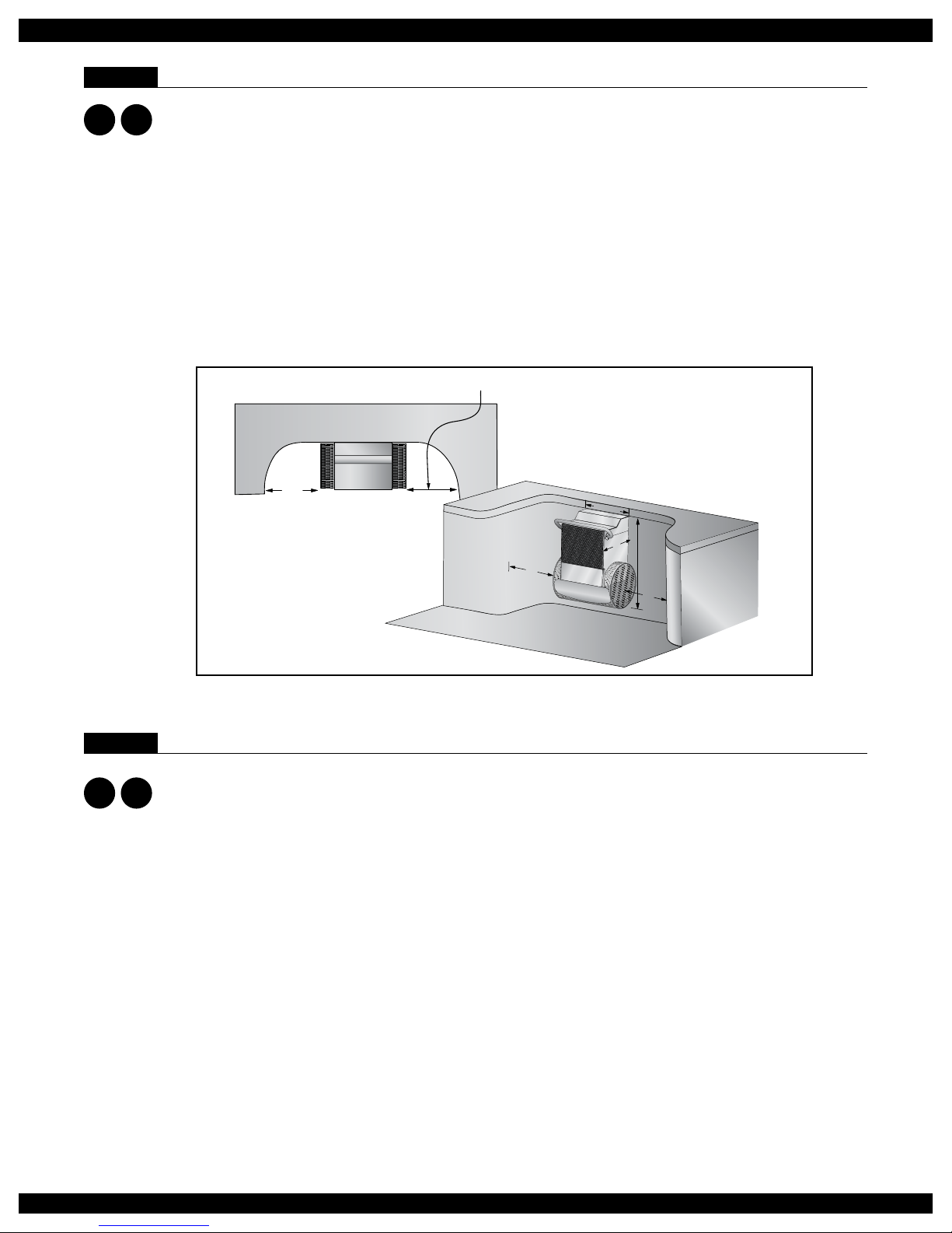
The Fastlane can t in virtually any swimming pool. For optimal water ow, we recommend that you allow
at least 12 feet (3,7m) between the wall on which the Fastlane is installed and the opposing wall in line with
the Swim Unit. The Fastlane has more than 9 square feet (.83m2) of water intake to eliminate any entrap-
ment hazards. The water depth where the Fastlane is installed must be at least 39" (99cm) deep. In addition,
the Fastlane must be installed no closer than 24" (61cm) from any adjacent wall as shown in Figure 2.1,
Minimum Clearance Guidelines.
When choosing a location for your Fastlane, you should also consider the route for the hydraulic hoses
to run back to the Power Unit. The Power Unit needs to sit on a solid, level surface, preferably not on
wet ground, and requires a 30-amp, 220-volt GFCI electric service. For UK and international electrical
requirements, please refer to Section 11. The optional Outdoor Power Unit with Weather Guard may be
located outside, but should not be subject to driving rain. Typically, the Power Unit is located with the other
pool equipment and, if possible, long hydraulic runs should be avoided because of pressure loss. If you
wish to have a run greater than 25' (7,6m), you must transition from 3/8" (9,5mm) hydraulic hoses to 1/2"
(12,7mm) run hoses with the addition of a junction box as reviewed in Section 5.
MINIMUM 24” (61cm)
24"
(61cm)
24
"
(61cm)
24
"
(61cm)
39
"
(99cm)
21
"
(53,3cm)
19"
(48,2cm)
Fig. 2.1 Minimum Clearance Guide
Section 3 RECEIVING YOUR FASTLANE
The Endless Pools Fastlane is comprised of a minimum of six (6) parcels. Additional parcels may be
shipped as appropriate. All items will be shipped via UPS Ground.
Items shipped UPS
Parcel 1: Fastlane Propulsion Housing Kit
Parcel 2: Fastlane Propulsion Base Kit
Parcel 3: Hydraulic Power Unit (wireless remote controls and antenna kit located inside controller)
Parcel 4: Hydraulic Fluid (5 Gallon container)
Wall Mount Fastlane
Parcel 5: Wall Mount Fastlane Mounting Kit (wall mount bracket and hardware for wall mount kit)
Parcel 6: Accessory Kit for Fastlane (hat sections, propulsion housing lid, hardware kit
for Fastlane assembly)
Deck Mount Fastlane
Parcel 5: Accessory Kit for Fastlane (hat sections, propulsion housing lid, hardware kit
for Fastlane assembly)
Bracket Kit for Deck Mount Fastlane (hanging bracket, deck plate, hardware for bracket kit)
Optional Equipment
Weather Guard Floor Mirror
Swim Pace Display Wi-Fi Kit (included in the accessory kit if purchased)
W
W
D
D
5

Fastlane®Swim Unit Installation Fastlane®Swim Unit Installation
Section 4 WALL MOUNT BRACKET
Note: Please read instructions fully prior to installing the wall mount bracket.
4.A. Gunite Pool
If the pool being constructed is gunite, please follow the instructions below.
The Wall Mount Fastlane Mounting Kit for Gunite pools includes the following:
(refer to Fig 4.1)
(1) PVC Wall Bracket
(2) Bonding Clamp
(2) 3/8" (9,5mm) Stainless Steel Threaded Mounting Rod
(6) 3/8" (9,5mm) Stainless Steel Jam Nut
(6) 3/8" (9,5mm) Stainless Steel Flat Washer
(2) 3/8" (9,5mm) Stainless Steel Lock Washer
(2) 1-1/2" (38mm) Thru-Wall Fitting
(2) 1-1/2" (38mm) MPT x 1” (25mm) FPT Bushing Reducer
(2) 1" (25mm) Liquid Tight Fitting
1" (25mm)
Liquid Tight Fitting
1-1/2" (38mm) x 1" (25mm)
Bushing Reducer
Thru-Wall Fitting
Rubber Gasket
Threaded Rod
1-1/2" (25mm) PVC Flex
(Supplied By Others)
Thru-Wall Fitting
Lock Nut
Cork Gasket
Bonding Clamp
Wall Bracket
Jam Nut
Lock Washer
Flat Washer
Flat Washer/Jam Nut
(Back Of Bracket)
Flat Washer/Jam Nut
(Front Of Bracket)
Fig. 4.1
Secure the thru-wall ttings to the bracket as shown in Fig 4.1. The rubber gasket should be between the
thru-wall and the bracket on the poolside of the bracket and the cork gasket should be between the bracket
and the locknut on the outside. Tighten the lock nut with a pair of channel locks or strap wrench.
W
6

Fastlane®Swim Unit Installation
The bracket is to be installed into the pool wall as shown in Figure 4.2 so that the two threaded mounting
rods are 1-1/2" (38mm) above the intended waterline for the pool, which is typically halfway up the skim-
mer. The "Waterline" mark on the bracket will sit along the pools intended waterline.
Level and position the bracket so that the PVC surface of the bracket will be ush with the nished surface
of the pool wall as shown in Figures 4.2. and 4.5. The area below the bracket should be no more than 5
degrees less than the vertical down to at least 39" (99cm) below the waterline. The Fastlane is 21" (53,3cm)
wide. Consequently, the 21" (53,3cm) section of wall where the bracket is located should be straight or
near straight.
The threaded rods attached to the bracket must be tied back to the rebar of the pool with rebar wire. Once
encased in concrete, these rods will serve as a suitable hanger. The threaded rods must penetrate 1-1/4" to
1-1/2" (31,8mm x 38mm) into the nished pool and will be used to hang the Fastlane
Rebar Grid
Tie Threaded Rods to
rebar with rebar wire
Finished
Pool Wall
Wall Bracket
flush with
finished pool wall
Threaded Rods
1-1/2" (38mm)
above pools waterline
Fig. 4.2
7
W

Fastlane®Swim Unit Installation Fastlane®Swim Unit Installation
Once the bracket is tied back to the rebar and positioned, unroll the exible PVC from the wall mount
bracket back to the hydraulic power unit. Any bends in the exible PVC should be gradual sweeps and not
sharp to allow the hydraulic hoses to easily be fed through each conduit. Each length of PVC must be no
longer than 21ft (6,4m) and should exit the ground near the hydraulic power unit. Glue the PVC ex pipe
into the thru-wall ttings at the wall mount bracket (Fig 4.3).
1-1/2" (38mm)
PVC Flex Pipe
Fig. 4.3
If the distance between the wall mount bracket and the hydraulic power unit is greater than 25ft (7,6m)
then a junction box and additional ex pipe must be employed. In this case, the ex pipe between the wall
mount bracket and the junction box must be 24ft 6in (7,5m). This will allow the hydraulic hoses attached to
the Fastlane to terminate just inside the junction box. See section 5 for additional information.
The threaded rods must be tied into the pools bonding grid. Secure a bonding clamp to each threaded
rod. Attach a #8 solid copper wire to each bonding clamp. These wires MUST be attached to a bonding
connection that’s incorporated into the pools bonding grid. In most cases this will be a connection at the
rebar. Verify ALL bonding connections are tight before shooting gunite (Fig 4.4).
W
8

Fastlane®Swim Unit Installation
Bonding Clamp
(See Detail A)
Bonding Clamp
#8 Solid Copper Wire
MUST BE ATTACHED TO
POOL BONDING GRID
Threaded
Rod
DETAIL A
Fig. 4.4
Prior to shooting gunite, it is critical that the opening of each thru-wall and the threaded rods that extend
into the nished pool be covered. No gunite can be embedded in these areas.
After verifying the bracket is positioned, bonding connections are secure, and thru-wall openings/threaded
rods are covered, gunite can be shot (Fig 4.5).
Finished Pool Wall
Fig. 4.5
.
9
W

Fastlane®Swim Unit Installation Fastlane®Swim Unit Installation
4.B. Steel/Polymer Pool with a Vinyl Liner
If the pool being constructed is a steel or polymer pool with a vinyl liner, please follow
the instructions below.
The Wall Mount Fastlane Mounting Kit for steel/polymer/gunite pools with a vinyl
liner includes the following:
(1) PVC Wall Bracket
(2) Bonding Clamp
(2) 3/8" (9,5mm) Stainless Steel Threaded Mounting Rod
(2) 3/8" (9,5mm) Stainless Steel Coupler
(2) 3/8" (9,5mm) Stainless Steel Threaded Stud
(4) 3/8" (9,5mm) Stainless Steel Jam Nut
(2) 3/8" (9,5mm) Stainless Steel Flat Washer
(2) 3/8" (9,5mm) Stainless Steel Lock Washer
(2) 3/8" (9,5mm) Rubber Washer
(2) 3/8" (9,5mm) Stainless Steel with Neoprene (Sacricial Washer)
(2) 3/8" (9,5mm) Stainless Steel Hex Head Bolt (Sacricial Bolt)
(2) 1-1/2" (38mm) Star Thru-Wall Fitting
(2) 1-1/2" (38mm) MPT x FSlip Adapter
(2) 1-1/2" (38mm) MPT x 1” (25mm) FPT Bushing Reducer
(2) 1" (25mm) Liquid Tight Fitting
(1) Clear Silicone
Position the PVC template where the Fastlane will attach to the pool wall and align the bottom of the
template with the expected water level in the pool (which will typically be located at the centerline of the
skimmer) as shown in Figure 4.6. Use duct tape to temporarily adhere the PVC template to the pool wall.
Be certain that the PVC template is level in the pool. Trace the outline of the star thru-wall ttings and
threaded rod hole penetrations that are cut in the PVC template onto the pool wall. Remove the PVC tem-
plate from the pool wall. Cut or punch the openings for the star thru-wall ttings and threaded rod holes.
Fig. 4.6
W
10

Fastlane®Swim Unit Installation
Install the star thru-wall ttings with the holes for the cover at 12, 3, 6, and 9 (clock positions) as shown in
Figure 4.7
Pool Wall
Holes in thru-wall fitting
oriented at 12, 3, 6, 9
clock positions
Star Thru-Wall Fitting
Fig. 4.7
Thread the 3/8" (9,5mm) jam nut onto the threaded rod. Thread the hex coupling onto the threaded rod so
that half of the hex coupling is threaded onto the rod and the other half that’s facing the pool is protruding
off the threaded rod. Tighten the jam nut so that its ush with the hex coupling to prevent the hex coupling
from threading further onto the rod. On the outside of the pool (backside of the pool wall), position each
rod and hex coupling to align with the 3/8" (9,5mm) holes drilled (Fig 4.8).
DETAIL A
Threaded Rod
(See Detail A)
Backside of pool wall
Threaded Rod
Hex Coupling
Jam Nut
Fig. 4.8
W
11

Fastlane®Swim Unit Installation Fastlane®Swim Unit Installation
On the inside of the pool, thread the sacricial 3/8" (9,5mm) steel (with rubber washer) and bolt into the
hex coupling through the hole that was previously drilled in the steel wall. Tighten the bolt to secure the
assembly (Fig 4.9).
Inside Pool Wall
Sacrificial Hardware
(See Detail A)
Sacrificial
Bolt
Sacrificial
Washer
Hex Coupling
DETAIL A
Fig. 4.9
Apply Teon thread sealant to the threads of the 1/1/2" (38mm) MPT x FSlip adapters and thread them
into the backside of the star thru-wall ttings. Unroll the exible PVC from the wall mount bracket back to
the hydraulic power unit. Any bends in the exible PVC should be gradual sweeps and not sharp to allow
the hydraulic hoses to be easily fed through the conduit. Each length of PVC must be no longer than 21ft
(6,4m) and should exit the ground near the hydraulic power unit. Glue the PVC ex pipe into the adapter
and run the pipe back to the power unit (Fig 4.10)
Adapter and Flex Pipe
(See Detail A)
1-1/2" (38mm)
PVC Flex Pipe
1-1/2" (38mm)
MPT x FSlip
Adapter
DETAIL A
Fig. 4.10
If the distance between the wall mount bracket and the hydraulic power unit is greater than 25ft (7,6m)
then a junction box and additional ex pipe must be employed. In this case, the ex pipe between the wall
mount bracket and the junction box must be 24ft 6in (7,5m). This will allow the hydraulic hose attached to
the Fastlane to terminate just inside the junction box. Refer to section 5 for additional information.
12
W

Fastlane®Swim Unit Installation
The threaded rods must be tied into the pools bonding grid. If using rebar in the pools concrete collar,
tie the threaded rods to the rebar using rebar wire. Secure a bonding clamp to each threaded rod. Attach
a #8 solid copper wire to each bonding clamp. These wires MUST be attached to a bonding connection
that’s incorporated into the pools bonding grid. In most cases this connection will be at the pools existing
equipment (heater, pump, etc.) that’s presumably already tied into the bonding grid of the pool. Verify these
connections are tight before pouring concrete (Fig 4.11)
Bonding Clamp
#8 Solid
Copper
Wire
DETAIL A
Bonding Clamp
(See Detail A)
Threaded
Rod
Fig. 4.11
Prior to pouring concrete, it is critical that the opening of each thru-wall and the sacricial bolt be covered.
No concrete can be embedded in these areas. Pour the concrete collar around the top ange of the pool
encasing the threaded rods and conduit in place. This encasement will help secure the Fastlane (Fig 4.12).
Concrete Collar
PVC Flex Pipe
Pool Wall
Bonding Clamp
#8 Solid Copper Wire
MUST BE ATTACHED TO
POOL BONDING GRID
Threaded Rod
Fig. 4.12
W
13

Fastlane®Swim Unit Installation Fastlane®Swim Unit Installation
After the concrete has cured remove the sacricial 3/8” (9,5mm) washers and bolts and install the pool
liner. Before beginning the liner installation, be sure to note the orientation of the star thru-wall holes at the
12, 3, 6, and 9 (clock positions) as they will be hidden once the liner is installed. After the liner is installed,
add water to the pool to weigh the liner down pulling it tight. When the liner is tight, cut the holes for each
thru-wall tting and threaded rod hole using a sharp utility knife. Cut the holes as small as possible for the
threaded rods (Fig 4.13).
Remove sacrificial washers
and bolts BEFORE installing
the liner
Pool Liner
Cut holes in liner for the
thru-wall fittings using
the fitting as a template
Cut holes for the 3/8" (9,5mm)
threaded rods
Fig. 4.13
Using a scratch awl, poke the holes out in each star thru-wall tting (holes located in 12, 3, 6, 9 clock
positions) and install the thru-wall faceplates using the screws provided. Tighten the screws with a hand
screwdriver to avoid cracking the faceplates. Apply RTV or a similar caulk to the threaded stud and rubber
washer and thread each stud into the 3/8" (9,5mm) holes in the liner/pool wall making sure the rubber
washer is ush against pool liner. (Fig 4.14).
Pool Liner
Threaded Stud &
Thru-Wall Faceplates
(See Detail A)
Thru-Wall
Faceplate
Faceplate
Screw
Rubber Washer
Threaded
Stud
DETAIL A
Fig. 4.14
W
14

Fastlane®Swim Unit Installation
4.C. Gunite Pool with a Vinyl Liner
If the pool being constructed is a gunite pool with a vinyl liner, please
follow the instructions below.
The Wall Mount Fastlane Mounting Kit for steel/polymer/gunite pools with a vinyl
liner includes the following:
(1) PVC Wall Bracket
(2) Bonding Clamp
(2) 3/8” (9,5mm) Stainless Steel Threaded Mounting Rod
(2) 3/8” (9,5mm) Stainless Steel Coupler
(2) 3/8” (9,5mm) Stainless Steel Threaded Stud
(4) 3/8” (9,5mm) Stainless Steel Jam Nut
(2) 3/8” (9,5mm) Stainless Steel Flat Washer
(2) 3/8” (9,5mm) Stainless Steel Lock Washer
(2) 3/8” (9,5mm) Rubber Washer
(2) 3/8” (9,5mm) Stainless Steel with Neoprene (Sacricial Washer)
(2) 3/8” (9,5mm) Stainless Steel Hex Head Bolt (Sacricial Bolt)
(2) 1-1/2” (38mm) Star Thru-Wall Fitting
(2) 1-1/2” (38mm) MPT x FSlip Adapter
(2) 1-1/2” (38mm) MPT x 1” (25mm) FPT Bushing Reducer
(2) 1” (25mm) Liquid Tight Fitting
(1) Clear Silicone
Install the star thru-wall ttings in the cutouts of the wall mount bracket making sure the holes in the t-
tings are oriented in the 12, 3, 6, and 9 (clock positions) as shown in Figure 4.15.
Thru-Wall Lock Nut
Star Thru-Wall
Fitting
Wall Mount Bracket
Holes in fitting at 12, 3, 6, 9
clock positions
Fig. 4.15
W
15

Fastlane®Swim Unit Installation Fastlane®Swim Unit Installation
Thread the 3/8” (9,5mm) jam nut onto the threaded rod. Thread the hex coupling onto the threaded rod so
that half of the hex coupling is threaded onto the rod and the other half that’s facing the pool is protruding
off the threaded rod. Tighten the jam nut so that its ush with the hex coupling to prevent the hex coupling
from threading further onto the rod (Fig 4.16).
Threaded Rod
Hex Coupling
Jam Nut
Fig. 4.16
On the backside of the bracket, position each threaded rod with the hex coupling to align with the 3/8"
(9,5mm) holes. On the front of the bracket, thread the sacricial 3/8" (9,5mm) steel with rubber washers
and bolts into the hex couplings (Fig 4.17).
Sacrificial Bolt
Sacrificial Washer
Threaded Rod
Assembly
Fig. 4.17
W
16

Fastlane®Swim Unit Installation
The bracket is to be installed into the pool wall so that the two threaded rods are 1-1/2" (38mm) above the
intended waterline, which is typically halfway up the skimmer. The bottom straight edge of the bracket
should be aligned with the expected waterline. Level and position the bracket so that the PVC surface of the
bracket will be ush with the nished surface of the pool wall. The threaded rods attached to the bracket
must be tied back to the rebar of the pool with rebar wire. Once encased in concrete, these rods will serve
as a suitable hanger. The threaded rods must penetrate 1-1/4" to 1-1/2" (31,8mm x 38mm) into the nished
pool and will be used to hang the Fastlane (Fig 4.18).
Tie Threaded Rods to
rebar with rebar wire
Rebar Grid
Finished Pool Wall
Wall Bracket
flush with
finished pool wall
Threaded Rods
1-1/2" (38mm)
above pools waterline
Fig. 4.18
Apply Teon thread sealant to the threads of the 1/1/2" (38mm) MPT x FSlip adapters and thread them
into the backside of the star thru-wall ttings. Unroll the exible PVC from the wall mount bracket back to
the hydraulic power unit. Any bends in the exible PVC should be gradual sweeps and not sharp to allow
the hydraulic hoses to be easily fed through the conduit. Each length of PVC must be no longer than 21ft
(6,4m) and should exit the ground near the hydraulic power unit. Glue the PVC ex pipe into the adapter
and run the pipe back to the power unit (Fig 4.19).
Adapter and Flex Pipe
(See Detail A)
DETAIL A
1-1/2" (38mm)
PVC Flex Pipe
1-1/2" (38mm)
MPT x FSlip
Adapter
Fig. 4.19
W
17

Fastlane®Swim Unit Installation Fastlane®Swim Unit Installation
If the distance between the wall mount bracket and the hydraulic power unit is greater than 25ft (7,6m)
then a junction box and additional ex pipe must be employed. In this case, the ex pipe between the wall
mount bracket and the junction box must be 24ft 6in (7,5m). This will allow the hydraulic hose attached to
the Fastlane to terminate just inside the junction box. Refer to section 5 for additional information.
The threaded rods must be tied into the pools bonding grid. Secure a bonding clamp to each threaded
rod. Attach a #8 solid copper wire to each bonding clamp. These wires MUST be attached to a bonding
connection that’s incorporated into the pools bonding grid. In most cases this will be a connection at the
rebar. Verify ALL bonding connections are tight before shooting gunite (Fig 4.20).
Bonding Clamp
(See Detail A)
Bonding Clamp
Threaded Rod
DETAIL A
#8 Solid Copper Wire
MUST BE ATTACHED TO
POOL BONDING GRID
Fig. 4.20
Prior to shooting gunite, it is critical that the opening of each thru-wall and the sacricial bolt be covered.
No gunite can be embedded in these areas.
After verifying the bracket is positioned, bonding connections are secure, and thru-wall openings/sacricial
bolts are covered, gunite can be shot.
After the concrete has cured remove the sacricial 3/8” (9,5mm) washers and bolts and install the pool
liner. Before beginning the liner installation, be sure to note the orientation of the star thru-wall holes at the
12, 3, 6, and 9 (clock positions) as they will be hidden once the liner is installed (Fig 4.21).
Sacrificial Hardware
(See Detail A)
Sacrificial Washer
Sacrificial Bolt
DETAIL A
Fig. 4.21
W
18

Fastlane®Swim Unit Installation
After the liner is installed, add water to the pool to weigh the liner down pulling it tight. When the liner is
tight, cut the holes for each thru-wall tting and threaded rod hole using a sharp utility knife. Cut the holes
as small as possible for the threaded rods (Fig 4.22).
Pool Liner
Cut holes in liner for the
thru-wall fittings using
the fitting as a template
Cut holes for the 3/8" (9,5mm)
threaded rods
Fig. 4.22
Using a scratch awl, poke the holes out in each star thru-wall tting (holes located in 12, 3, 6, 9 clock
positions) and install the thru-wall faceplates using the screws provided. Tighten the screws with a hand
screwdriver to avoid cracking the faceplates. Apply RTV or a similar caulk to the threaded stud and rubber
washer and thread each stud into the 3/8" (9,5mm) holes in the liner/pool wall making sure the rubber
washer is ush against pool liner (Fig 4.23).
Threaded Studs &
Thru-Wall Faceplates
(See Detail A)
Thru-Wall
Faceplate
Faceplate
Screw
Rubber Washer
Threaded
Stud
DETAIL A
Fig. 4.23
W
19
Other manuals for FastLane
6
Table of contents
Other Endless Pools Lighting Equipment manuals
Popular Lighting Equipment manuals by other brands

Gamma+
Gamma+ Rose LED Zoom user manual

Dop Choice
Dop Choice SNAPGRID operating instructions

Lightmybricks
Lightmybricks 71016 installation instructions

STREET WISE
STREET WISE SAFEZONE SWSZSL20 instructions

Astral Pool
Astral Pool Glassy L Installation, operation and manteinance manual

Blue Wave
Blue Wave NE145 Assembly instructions

DekoLight
DekoLight 180136 manual

Show Tec
Show Tec Showdesigner 1024 Product guide

Delta Light
Delta Light KIX M1 Installation instruction

Prima Klima
Prima Klima SPUDNIK L1400/125 Information and safety sheet

Claypaky
Claypaky Display Line C52146 operating instructions

SUPER NOVA
SUPER NOVA MOD-1614D Assembly instructions