Endless Pools FastLane Assembly instructions

INSTALLATION GUIDE
AND USER’S ANUAL
Fastlane Pool

1
IMPORTANT SAFETY INFORMATION
SAVE THESE INSTRUCTIONS
BEFORE INSTALLING OR USING THIS PRODUCT, READ AND
FOLLOW ALL SAFETY INSTRUCTIONS. FAILURE TO DO SO
CAN RESULT IN PROPERTY DAMAGE, INJURY, OR DEATH
SERIOUS BODILY INJURY OR DEATH CAN RESULT IF THIS
PRODUCT IS NOT INSTALLED OR USED CORRECTLY
CHILDREN SHOULD NEVER SWIM UNSUPERVISED
RISK OF ELECTRICAL SHOCK-
•All electrical connections should be made by a licensed electrician in
accordance with the all applicable National and local code and
ordinances.
•This product must not be installed within 5 feet (1,5m) of any metal
surface, unless the surface has been properly bonded and/or grounded
in accordance with any applicable national or local electrical code.
•Improper installation will create a hazardous situation that can result
in property damage, injury, or death.
This product must be installed in accordance with any applicable state and
local code. Consult your local building and health code for more
information.
IT IS THE RESPONSIBILTY OF THE END USER TO ENSURE THAT ANYONE
WHO USES THIS PRODUCT IS PROPERLY INFORMED OF ALL SAFTEY
PRECAUTIONS.
ALL SAFETY SIGNS PROVIDED WITH THIS PRODUCT SHOULD BE
PERMANENTLY INSTALLED SO THAT THEY ARE VISIBLE TO ALL
OCCUPANTS. SHOULD YOU REQUIRE ADDITIONAL SIGNS OR
REPLACEMENTS, CONTACT CUSTOMER SERVICE.
!
WARNING
!
WARNING
!
WARNING
!
WARNING
!
WARNING

2
RISK OF ELECTRICAL SHOCK
A G OUND FAULT CI CUIT INTE UPTE (GFCI) O ESIDUAL CU ENT DEVICE ( CD) is
required for this product. The Ground Fault Circuit Interrupter (GFCI) or esidual Current Device
( CD) is NOT provided with this product. One must be sourced locally and installed into the panel
box by a licensed electrician when making the electrical connections to the spa equipment.
Test the Ground Fault Circuit Interrupter (GFCI) or esidual Current Device ( CD) prior to each
use to ensure that it works properly.
DO NOT permit any electrical equipment appliance such as lights, radio, television, or telephone
within 5 feet (1,5m) of this product. DO NOT operate any such product while in this product or
while you are wet.
Electrical power should be shut off to this product prior to any service being performed.
GROUND ALL ETAL EQUIP ENT
A green colored terminal labeled G is found inside the heater-controller. Inside both the optional
hydraulic power unit and inside the load center box there are terminal bus bars used exclusively for
grounding purposes. These terminals must be connected to the grounding means provided in the
electrical supply panel, using a continuous copper wire equivalent in size to the circuit conductors
supplying this equipment.
The electrical components inside the spa cabinet will have means to connect the local common
bonding grid. Connect these components to the bonding grid using an insulated or bare copper con-
ductor not smaller than a No. 6 AWG.
All field installed metal components (ladders, handrails, etc.) or metal surfaces must be connected to
the local bonding grid.
TO REDUCE THE RISK OF ACCIDENTAL DROWNING
Children should never be allowed to use this product without adult supervision.
Children should never have unsupervised access to this product.
TO AVOID THE RISK OF INJURY
Pregnant women (or possibly pregnant women should consult a physician prior to using this product.
High water temperatures have a high potential for causing damage to the fetus in the early stages of
pregnancy.
Anyone taking medication should consult a physician prior to using this product.
Anyone under the influence of drugs or alcohol should not use this product.
Anyone with an infectious disease or with an open wound or sore should not use this product.
Anyone who has a history of heart disease, high or low blood pressure, circulatory system problems,
diabetes, or someone is who is battling obesity should consult a physician prior to using this product.
!DANGER
!WARNING
!WARNING
!WARNING

3
TO REDUCE THE RISK OF DROWNING
Prolonged immersion in high temperature water can cause hyperthermia. Hyperthermia occurs
when the internal temperature of the body is several degrees higher than the normal 98.6°F (37°C).
The symptoms of hyperthermia include dizziness, lethargy, drowsiness, and fainting. The effects of
hyperthermia include:
1. Failure to perceive heat
2. Failure to recognize the need to exit the water
3. Unawareness of a hazardous situation
4. Fetal damage in pregnant women
5. Physical inability to exit the water
6. Unconsciousness- which can lead to drowning
Keep hair and body parts away from suction fittings. Long hair should not be allowed
to float freely in the water. Hair should be tied up or placed under a bathing cap.
RISK OF INJURY
Do not remove or tamper with any suction fitting. NEVE operate this
product if a suction cover is missing or damaged.
All suction fittings in this product are sized to match the flow rate.
Always use compatible suction fittings should they need to be replaced.
NEVE replace a suction fitting with one rated less than the flow rate
marked on the original suction fitting.
Never use this product alone.
Always completely remove the cover prior to using this product.
Water will splash out of this product. The finish surface immediately
surrounding this product should be a non-slip material.
TO REDUCE RISK OF DROWNING
The water in this product must never exceed 104ºF (40ºC).
Safe water temperature for Aquatic Exercise is approximately 80ºF (27ºC).
TO AVOID INJURY
DO NOT use this product alone.
emove all jewelry, watches, etc. prior to using this product.
Use caution when entering and exiting this product as wet surfaces can be slippery.
RISK OF INJURY
Keep all breakables, especially glass, away from this product.
Never insert any objects into any openings.
TO AVOID RISK OF INJURY
Keep all chemicals away from children and pets.
DO NOT stack chemicals on top of one another.
NEVE MIX CHEMICALS.
Sanitizing chemicals must be stored separately from balancing chemicals.
!DANGER
!WARNING
!DANGER
!WARNING
!WARNING
!WARNING

4
Endless Pools, Inc. provides for every aspect of a Fastlane Pool project. This manual assists in the installation process,
as well as the general maintenance of your Fastlane Pool.
Additional available resources including the Planning Guide and selected Supplemental Guides are available to you. These
documents are available online at www.myendlesspool.com/downloads.html. In addition, we encourage installers to call
our Customer Service Department at 800-910-2714 (US), 0800-520-0196 (UK) or 610-497-4538 (Direct) before beginning
installation to register their projects and sign up for weekend technical support.
Please be advised that gloves and safety goggles should be worn during the installation of a Fastlane Pool.
Shipping regulations have dictated that the following chemicals cannot be shipped to Alaskan, Hawaiian, or International cus-
tomers due to their hazardous nature: 4oz PVC cleaner, 4oz PVC Cement, 2 lb pH decreaser, and 1 lb bag of shock. If needed,
these chemicals will have to be obtained locally.
Please take into consideration the following before proceeding:
If you have purchased the Optional Heater/Controller package, that will require a 3-wire (w/ neutral) 220v, 30 amp,
GFCI power supply.
If you have purchased the standard package, then no neutral is required and the white wire can be left unused.
• The Submerged Suction Outlet odel #29-19 (part # 124011) is certified only for use with the Endless Pool Fastlane system.
It may not be used in any other application.
• This Submerged Suction Outlet odel #29-19 (#124011) may only be installed as described in this anual. The Submerged
Suction odel #29-19 (part #124011), is 19" in diameter and 29" long and is constructed of 316L perforated stainless steel. It
should be replaced after 25 years using a #2 Phillips head screwdriver. It shall be marked with the following label: VGB 2008
SUB ERGED SUCTION 29-19, #124011. FOR USE ONLY WITH FASTLANE® SWI ING ACHINE ANUFAC-
TURED BY ENDLESS POOLS, INC. LIFE: 25 YEARS, WALL ONLY. AXI U FLOW FRO SINGLE 5 HP POWER
UNIT WITH ALP2-16 GEAR PU P PRESET TO AXI U FLOW OF 4.8 GP UTILIZING 16" DIA ETER OPEN
FLOW PROPELLER. ENDLESS POOLS, INC. ANSI/APSP-16 2011
• The Submerged Suction Outlet odel #29-19 (part #124011) does not require routine service during the year or as part of
Endless Pool winterizing procedures.
• Before each use verify that the Submerged Suction odel #29-19 (part #124011), including the fasteners, is undamaged and
has not been tampered with.
• Do not use the Fastlane if there is any evidence of damage or tampering. Call the Endless Pools Customer Service Department
at 800 910 2714 immediately. The Submerged Suction odel #29-19 must be secured as described in this anual before the
Fastlane is used again.
• Do not increase the flow through the Submerged Suction odel #29-19 (part #124011) by increasing the size of the pump.
• Please read and then keep these instructions for future reference.
Assembly Instructions
Note: all of the 316L stainless steel screws provided for the assembly of the Fastlane should be tightened to the recommended
25 in-lbs of torque.
Installation Instructions Table of Contents
Receiving the Fastlane Pool. . . . . . . . . . . . . . . . . . . . . . . . . 5
Pool Positioning . . . . . . . . . . . . . . . . . . . . . . . . . . . . . . . . . . 6
Site and Pool Preparation. . . . . . . . . . . . . . . . . . . . . . . . . . . 6
Pool Assembly . . . . . . . . . . . . . . . . . . . . . . . . . . . . . . . . . . . 6
Thru-Wall Connections . . . . . . . . . . . . . . . . . . . . . . . . . . . . 8
Skimmer Assembly . . . . . . . . . . . . . . . . . . . . . . . . . . . . . . . 9
Skimmer and Return Connections . . . . . . . . . . . . . . . . . . . . 9
Fastlane Swim Unit Assembly . . . . . . . . . . . . . . . . . . . . . . 10
Fastlane Hydraulic Power Unit Assembly . . . . . . . . . . . . . 13
Assembling the Water Quality System
Without Heater Controller . . . . . . . . . . . . . . . . . . . . . . . . . 13
Assembling the Water Quality System
With Heater Controller. . . . . . . . . . . . . . . . . . . . . . . . . . . . 14
Electrical Requirements and Connections 60Hz . . . . . . . . 15
Electrical Requirements 50Hz . . . . . . . . . . . . . . . . . . . . . . 16
Bonding and Grounding. . . . . . . . . . . . . . . . . . . . . . . . . . . 16
Fastlane Pool Equipment Hutch Assembly . . . . . . . . . . . . 17
Installing an Antenna Extension . . . . . . . . . . . . . . . . . . . . 17
Remote Control Transmitter. . . . . . . . . . . . . . . . . . . . . . . . 17
Initial Start Up . . . . . . . . . . . . . . . . . . . . . . . . . . . . . . . . . . 18
Keypad Functions. . . . . . . . . . . . . . . . . . . . . . . . . . . . . . . . 18
Using the Fastlane Swim Unit . . . . . . . . . . . . . . . . . . . . . . 18
Caring for the Fastlane Pool . . . . . . . . . . . . . . . . . . . . . . . 18
Troubleshooting . . . . . . . . . . . . . . . . . . . . . . . . . . . . . . . . . 21
Fastlane Pool Warranty . . . . . . . . . . . . . . . . . . . . . . . . . . . 22
Wiring Schematic 60Hz . . . . . . . . . . . . . . . . . . . . . . . . . . . 23
Wiring Schematic 50Hz . . . . . . . . . . . . . . . . . . . . . . . . . . . 24

5
RECEIVING THE FASTLANE POOL
The Fastlane Pool is shipped via UPS and contains at least 16
packages. Additional packages may be sent depending on the
options chosen:
(1) Hydraulic ower Unit
(Box labeled, “Power Unit Kit, 5Hp 60Hz, with Electronics, for
Poolside WQS with 3/12/09 Card 451000” for US Customers
and “Power Unit Kit, 5Hp 50Hz, with Electronics, for Poolside
WQS with 3/12/09 Card 451020” for International Customers)
(1) 5 Gallon Hydraulic Fluid
(1) Fastlane ool Swim Unit Housing
(Box labeled, “Fastlane Upper Unit for Rolled Perf Base,
Sapphire 124016”)
(1) Fastlane ool Accessories Kit
(Box labeled Accessory Kit for Fastlane Pool w/ Rolled Perf
Base, Sapphire 124026)
Qty 2 - Hydraulic Hose Protective Channels
Qty 1 - Acrylic Top for Swim Unit
Qty 1 - Acrylic Hanging Bracket
Qty 1 - Lower Standoff
Qty 1 - Owner’s Manual Kit (Padded Envelope)
Qty 1 - Owner’s Manual
Qty 2 - Hydraulic Adapters (8 Female JIC x 6 Male JIC)
Qty 1 - Fastlane Pool Bonding Kit
Qty 38 - 3/4" 10-32 Machine Screws
Qty 10 - 1/2" 10-32 Machine Screws
Qty 4 - Rubber rommets
Qty 6 - 10-32 nuts
(1) Fastlane ool Swim Unit Base
(Box labeled Fastlane Lower Unit for Rolled Perf Base,
Sapphire 124011)
(1) Fastlane ool Liner Box (Only for a 9x13 ool)
(Box labeled, “Fastlane Pool Liner Box, 9 x 13 157070”)
Qty 1 - Pool Liner
Qty 2 - Vertical Struts
Qty 4 - Top Corner Tubes
Qty 4 - Bottom Corner Tubes
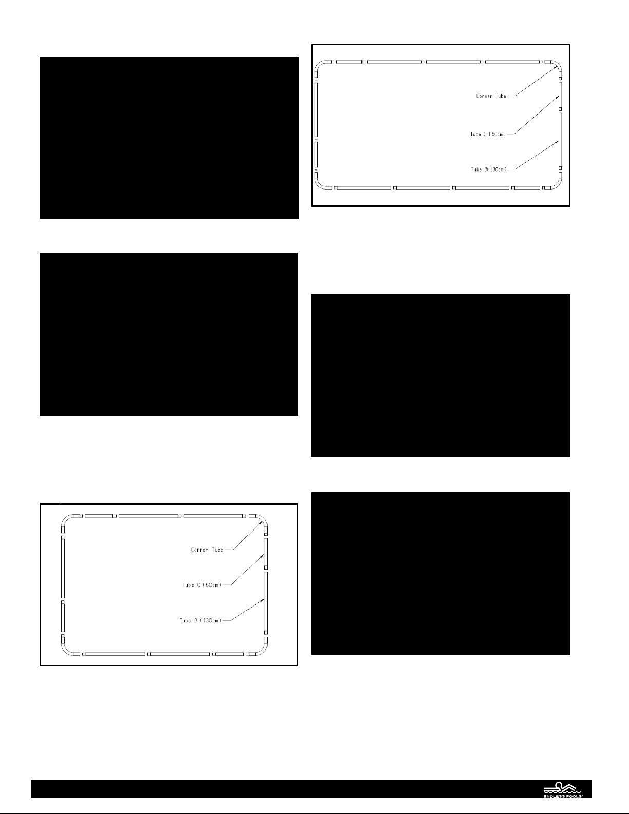
(1) Fastlane ool Liner Box (Only for a 9x17 ool)
(Box labeled, “Fastlane Pool Liner Box, 9 x 17 157072”)
Qty 1 - Pool Liner
Qty 4 - Vertical Struts
Qty 4 - Top Corner Tubes
Qty 4 - Lower Corner Tubes
Qty 2 - 130cm Top Straight Tubes
Qty 2 - Straight Bottom Tubes
(1) Fastlane ool Strut Box
(Box labeled, “Fastlane Pool Strut Box 157067”)
Qty 8 - Vertical Struts
(2) Fastlane ool Tube Box
(Box labeled, “Fastlane Pool Tube Box 157068”)
Qty 3 - 130cm Top Straight Tubes
Qty 2 - 60cm Top Straight Tubes
Qty 3 - Straight Bottom Tubes
(1) Fastlane ool Equipment Hutch
(Box labeled, “Hutch Box for Fastlane Pool Equipment
157064”)
Qty 1 - Equipment Hutch
Qty 1 - Equipment Mounting Board
Qty 1 - Pump Mounting Clamp
(1) Fastlane ool Water Quality System
(Box labeled: Fastlane Pool, Skimmer Plumbing and start-up
Box with Teleweir Skimmer and Skimmer Housing [4302250])
Qty 1 - Skim-Filter
Qty 1 - Circulating Pump
Qty1 - Plumbing Parts bag
Qty 2 - Thru-wall Fittings
Qty 2 - MPT x Slip 90º Street Elbows
Qty 2 - Slip x Slip Unions
Qty 2 - Slip x Slip Ball Valves
Qty 2 - Pump Unions with O-Rings
Qty 1 - Male Slip x Female Slip 90º Street Elbow
Qty 2 - MPT x Insert 90º Elbow
Qty 2 - Plastic Hose Clamps
Qty 2 - Threaded Plug with O-Ring
Qty 1 - Eyeball Fitting
Qty 1 - 4oz PVC Cleaner
Qty 1 - 4oz PVC Cement
Qty 1 - Teflon Tape
Qty 1 - Liquid Tite Electrical Fitting
Qty 1 - 1-1/2" Slip x 1-1/2” Slip x 3/4” FPT Tee
Qty 1 - 3/4" Hose Spigot
Qty 1 - 2" Male Slip x 1-1/2"FPT Bushing Reducer
Qty 1 - Suction Fitting Assembly
Qty 1 - Skimmer Straight Nut
Qty1 - Fastlane Pool Start Up Bag
Qty 1 - Container of Test Strips
Qty 1 - Water Clarifier
Qty 1 - pH Increaser
Qty 1 - pH Decreaser
Qty 1 - Bag of Shock
Qty1 - Fastlane Pool Skim Filter Housing Assembly
Qty 1 - Skim Filter Housing
Qty 5 - 1/2" 10-32 Stainless Steel Machine Screws
Qty 5 - 1" Self Tapping Stainless Steel Screws
Qty 1 - 11/64" Drill Bit
Qty 1 - 3' Length of Suction Hose
(1) 50’ Roll of Flexible VC
(1) Fastlane ool Ladder
(1) Solar cover
(only shipped if a Retractable Security Cover Kit was not
ordered)
(1) Optional Heater Controller
(Box labeled, “Fastlane Pool Heater Kit, 60Hz 157073” for
US Customers and, “International Fastlane Pool Heater Kit,
50Hz 157069” for International Customers)
Qty 1 - Heater Controller
Qty 1 - Keypad for Heater Controller
Qty 2 - Heater Tail Piece
Qty 2 - Heater Tail Piece T askets
Qty 1 - Slip x Slip 90º Elbow
Qty 1 - Male Slip x Female Slip 90º Street Elbow
Qty 2 - 2-1/4" PVC Nipple
Qty 1 - 4-1/4" PVC Nipple
Qty 1 - Heater Controller Mounting Clamp
Qty 4 - 3/4" 10-32 Machine Screw
Qty 2 - 10-32 KEP Nut

6
POOL POSITIONING
To ensure ideal operation of the Fastlane Pool, consider the
following steps when selecting a location for the pool.
• Look for an area that receives maximum sunlight for
increased heat and extended use.
• Find a location with minimal wind exposure to minimize
heat loss.
• Be aware of the amount of trees and shrubbery around the
pool to limit the amount of debris that may accumulate in the
pool.
• Select a location with accessibility to water and electric
sources.
• Consider privacy when selecting a location.
SITE AND POOL PREPARATION
The surface that the Fastlane Pool is to be assembled on must be
firm and level. The Fastlane Pool must be installed as level as
possible, within 2"- 3" of level (from the highest point to the
lowest point of the pool). If the pool will be assembled on a
sloping surface, be sure to install the skimmer on the lower side
to ensure that it will not draw air into the pump. If the ground is
not level and it is desired to make a more level surface, take the
earth from the high area of the uneven surface; do not add earth
to the low area of the surface. Once the surface is level, clear
any debris or sharp objects that may be uncomfortable to walk
on or could become a puncture hazard for the liner. Foam floor-
ing may be added under the liner for additional comfort.
The pool is comprised of various parts. Therefore, before
proceeding with installation, ensure that all necessary parts for
the pool are present and group like parts together (Fig 1).
art Description Quantity
(A) Liner 1
(B) Top 130cm straight tubes (wider) 6 (8 for Longer Pool)
(C) Top 60cm straight tubes (wider) 4
(D) Top corner tubes (wider) 4
(E) Bottom corner tubes (thinner) 4
(F) Straight bottom tubes (thinner) 6 (8 for Longer Pools)
( ) Struts 10 (12 for Longer
Pools)
The supporting legs, or struts (Part ), support much of the
weight of the Fastlane Pool and may need additional support in
“soft ground” installations, or in areas that may experience
excess ground water. A 2"x 8" x 22" piece of lumber installed
under each strut’s base and leveled with the ground is very
effective. Make sure the entire base of each strut is on the 2" x
8" lumber as any over-hang may result in bending of the strut.
A concrete slab of the similar dimensions may be used as well.
Please note that any support(s) added under the pool structure
must be recessed so that the top of the support is level with the
ground surface (Fig 2). Lifting the struts or frame in any manner
may cause excessive stress on the liner and frame, and may void
the Fastlane Pool warranty.
Drainage needs to be provided around the pool and near the
water quality equipment. It is important to be prepared in the
unlikely event of a leak. If operating the Fastlane Pool indoors,
it is ideal to install floor drains in the area around the pool’s
perimeter, but not directly under the pool. It is worth the time
and effort now to install a drainage system rather than be unpre-
pared in the event of a mishap.
POOL ASSE BLY
1. Unfold and spread out liner (Part A) on the prepared area.
NOTE: Keep in mind the desired “swim direction” when
positioning the liner, because when the Fastlane Pool is fully
assembled, the swim direction will be headed towards the end
of the pool that has the pre-cut holes. These holes are for the
water quality thru-wall fittings and hydraulic lines.
2. Align the struts (Part ) with the prepared cut outs at top of
liner (Fig 3).
3. Connect the bottom tubes (Part F) to the struts (Part ) one
at a time to make the four sides of the pool (Fig 4). Connect
corner tubes (Part E) to the open ends of both struts to finish
Fig. 1
Fig. 2
Fig. 3
A
B
G
FEC
D

each of the four corners. (Fig. 5).
4. Connect the top tubes (Parts B and C) together. NOTE: The
shorter tube (Part C) is always the last tube on the right when
facing the pool wall (See Fig 6 and Fig 7).
DIA RAM #2: WIDER STRAI HT TUBE LAYOUT
Fig. 6 - Standard (9' x 13') Fastlane Pool
Fig. 7 - Longer (9' x 17') Fastlane Pool
5. Feed the connected top tubes (Parts B and C) into the
corresponding sleeves of the liner (Fig 8). Be sure to align
the top tube slots with the matching cutouts (Fig 9) in the
liner, and then insert the corresponding struts (Part ) into
the top tube slots (Fig 10).
Fig. 4
Fig. 5
Fig. 8
Fig. 9
7

6. Insert and connect the top corner tubes (Part D). It may be
helpful to insert both ends of corner tube into the correspon-
ding liner sleeves, and then pull back on the corner tube to
connect one end at a time to the top rails (Parts B and C).
There are no spring clips on the corner tubes (Fig 11).
7. Ensure that all tubes around the perimeter are completely
nested in one another and properly connected, and that no
parts of the frame are racked or crooked. The liner should be
hanging evenly from the top tubes.
8. Slowly begin to fill the pool with water until the bottom of
the liner is almost taught. Remove any wrinkles in the pool
liner at this time, as it will be difficult to do so once there are
more than just a few inches of water in the pool.
9. To prevent leaking issues, it is very important to plumb and
plug both thru walls before the water level reaches the two
pre-cut holes in the liner. For more information, refer to
the section in this Owners’ Manual titled, THRU-WALL
CONNECTIONS.
THRU-WALL CONNECTIONS
There are 2 thru-wall penetrations for you water quality system.
There is a thru-wall fitting and a return thru-wall fitting. The
provided fittings will come with 3 gaskets (2 rubber and 1 cork).
Only two will be used in this application. One rubber gasket
will be used on the inside of the pool and the cork gasket will
be used on the outside of the pool. The following section will
give a more detailed instruction for these thru-wall fittings.
Thru-Wall Installation
1. Place a rubber gasket (#2) onto the thru wall fitting (#1) and
then insert the fitting into the hole in the liner (#3) from the
inside of the pool. The threaded body of the fitting should be
protruding outside the pool.
2. Place the paper/cork gasket (#4) onto the fitting outside the
pool. Then thread the locknut (#5) onto the fitting. Do not
over-tighten the fitting as this could cause the fitting to crack.
3. On the outside of the pool, attach the male thread x female
slip 90º elbow (#6) to the thru-wall fitting. Make sure to
apply Teflon tape to the threads of the elbow prior to attach-
ing. The elbow should be facing down.
4. Cut off a short length of flexible PVC (approx. 2 1/2") (#7)
from the large roll. lue that short length of pipe into the
elbow. Make sure that you apply PVC cleaner to both faces
of the joint prior to gluing.
5. Then glue the slip x slip union (#8) onto that short length of
pipe. The union should be disassembled prior to gluing so
that the union pieces are not glued to themselves.
6. The remaining flexible PVC will be used to connect the
plumbing assemblies at the pool to the Water Quality System.
The skimmer thru-wall will be on the right and the return
thru-wall will be on the left (as you are in the pool facing the
thru-wall penetrations). The skimmer thru-wall assembly
should be connected to the suction side of the pump and the
return assembly should be connected to the pressure side of
the pump (or to the optional heater). The Water Quality
System should be completely assembled prior to running the
flexible PVC lines.
Fig. 10
Fig. 11
Fig. 12
8

SKI ER ASSE BLY
1. Unthread the locking ring from the body of the skimmer-
filter
2. Place the skimmer-filter into the opening in the top of the
housing. There are two openings in the bottom of the skim-
mer-filter. Make sure that the opening labeled, “IN” is facing
one of the side panels of the housing. Re-install the locking
ring onto the skimmer-filter.
3. Use the provided PVC cement and cleaner to glue the 2”
male slip x 1-1/2” FPT bushing reducer into the, “OUT” port
of the skimmer-filter.
4. Wrap Teflon tape around the threads of one of the 1-1/2”
MPT x Insert 90º elbows. Thread that elbow into the bush-
ing reducer that was installed in the previous step. Make sure
that the elbow is facing down.
5. Use the provided PVC glue and cleaner to secure the skim-
mer straight nut into the “IN” port at the bottom of the skim-
mer-filter. Thread in the suction fitting assembly into the
adapter.
6. Attach the hanging brackets to the skimmer-filter housing.
Position the smaller face of the bracket onto the underside of
the housing so that the pre-drilled holes are aligned. Use the
provided stainless steel screws to attach.
7. Once the skimmer-filter assembly is complete, place it inside
the pool in the same corner as the lower thru-wall fitting
(front right).
8. Use the provided drill bit and self-tapping screw to attach the
skimmer assembly to the top tube of the pool. Position the
holes in the top of the bracket with the center of the top tube.
Drill through the liner and tube with the provided drill bit ant
then secure the assembly to the top tubes with the provided
self-tapping screws.
SKI ER-FILTER AND
RETURN CONNECTIONS
There are two thru-wall fittings installed in your pool (See the
section entitled, “Thru-Wall Connections”). The right thru-wall
fitting (as you are in the pool facing the front) is the suction fit-
ting and the left thru-wall fitting is the return fitting.
1. Wrap Teflon tape around the threads of the remaining 1-1/2”
MPT x Insert 90º elbow and secure that to suction thru-wall
fitting (front right) so that the elbow is facing down.
2. Loosely place a plastic hose clamp on each end of the flexi-
ble hose (packaged in the skimmer-filter housing box). Place
one end on the elbow attached to the skimmer-filter and the
other end onto the elbow attached to the suction thru-wall fit-
ting. Then tighten the plastic hose clamps.
Thread the lock-ring back
onto the filter body once the
housing is in place
Slide the skimmer-filter
into the opening
in the housing
Fig. 13
Suction Fitting Assembly
Skimmer Straight Nut
Bushing Reducer
Insert Elbow
"IN" Port
"OUT" Port
Fig. 14
3/4" Stainless Steel Screw x4
Fig. 15
1" Self-Drilling Screw
Pool Top Tube
Fig. 16
9

10
Return Connection
1. A directional eyeball fitting has been provided with the Water
Quality System. This eyeball fitting is to be secured to the
return thru-wall fitting (front left). For optimal heating of the
pool, make sure that the opening in the eyeball fitting is
pointing down.
FASTLANE SWI UNIT ASSE BLY
1. Carefully unpack the swim unit from its boxes. Make sure to
remove any hardware packs from the boxes as well. The
packaging can be collapsed and used as a protective surface
upon which to assemble the Fastlane. The foam packing
material can be used to wedge under the base to prevent it
from tipping over.
2. Take care when handling or working with any of the stainless
steel components of the swim unit. The ends can be sharp.
The first step is to remove the two circular end caps from
each side of the cylindrical base. There are 3 arced cover
strips around the perimeter of the end cap. Unthread the nine
screws that secure the cover strips (3 screws per cover strip).
Repeat this step for the other side of the stainless steel base.
Carefully set each end cap aside (Fig 19).
3. Uncoil the two lengths of hydraulic hose that are attached to
the cylindrical base. Make sure that the hoses are seated into
their respective notches in the backside of the base (Fig 20).
4. Remove the throat from the upper housing. There are two
screws on each side of the throat. Pull the throat off of the
housing and set it aside. Pull the vertical water-conditioning
grill up and out of the housing. Pull the horizontal grill out of
its track and remove from the housing. Make sure to remove
and discard the wood 2x4 spacer from the bottom of the
housing before proceeding (Fig 21).
5. Carefully remove the protective film encasing the upper
housing. Place the upper housing into the opening of the
cylindrical base (Fig 22). The hydraulic hoses connected to
the base should be aligned with the back of the upper hous-
ing. Make sure that the stainless steel bonding wire attached
to the motor mount is positioned inside of the upper housing.
Suction Hose
Hose Clamp Insert Elbow
Insert Elbow
Hose Clamp
Thru-Wall Fitting
Fig. 18
Repeat this process for the
other side of the stainless steel base
Remove these 9 screws
Arced Cover Strip
Circular End Cap
Fig. 19
Fig. 20
Fig. 21
Bond Wire
Fig. 22
Repeat this process for the
other side of the Fastlane 1" Machine Screw
(4 per side)

6. Use the provided stainless steel machine screws to attach the
upper housing to the base. There will be 4 screws per side
(total of 8). On each side of the housing, there will be 3
screws securing the upper housing to PVC motor mount sup-
port and 1 screw attaching the stainless steel reinforcing sup-
port to the housing just above the 3 previous screws (Fig 22).
7. Carefully lay the Fastlane onto its front face. Run the
hydraulic hoses up the back of the upper housing. The two
hat channels will be placed over the hydraulic hoses. Make
sure that the mounting hole in the end of the hat channel is
facing up and that the bottom of the hat channel has been
inserted into the notch in the cylindrical base. Use the pro-
vided 3/4" machine screws to attach the hat channels to the
upper housing. There will be eight screws per hat channel
(Fig 23).
8. Pull any excess hose out of the hat channel (Fig 24).
9. Slide the horizontal water-conditioning grill back into its
track inside the housing. The horizontal grill is the wider of
the two grills (Fig 25).
10. Install the stainless steel grab bar to the upper housing using
the provided machine screws and lock nuts. Feed the stain-
less steel wire attached to the motor mount up through the
horizontal grill. Then feed the wire up between two of the
turning vanes. Place the stainless steel wire (from the motor
mount in the base) around the bottom screw on the left side
before tightening down on the nut. Place the second stain-
less steel wire (that exits the top rear of the upper housing)
around another screw before tightening down on the nut
(Fig 26).
11. Reattach the throat (removed in step 4) to the upper housing.
Again, there will be 2 screws on either side of the throat
(total of 4) (Fig 27).
3/4” Machine Screws x16
Fig. 23
Fig. 24
Slide the Horizontal
Grill back into place
Fig. 25
Fig. 26
Fig. 27
11

12
13. Slide the vertical water-conditioning grill back down into
the housing (Fig 28).
14. Re-install the circular end caps. Make sure that the “smooth”
surface of the end caps are facing out. Align the end caps to
the internal PVC supports so that the holes in the internal
supports are aligned with holes in the end caps. Position the
arced cover strips over the end caps, making sure to align
the hole in the arced cover strips with the holes in the stain-
less end caps and the internal PVC supports. Install the nine
screws (3 per cover strip) that were removed in step 2.
Repeat for the remaining end cap (Fig 29).
15. Secure the Fastlane hanging bracket to the back of the
Fastlane with the provided 3/4" Machine Screws. The top
pair of screw holes in the back of the Fastlane should be
aligned with the holes that are second from the top of the
bracket. Additional holes have been placed in the bracket
should be level of the Fastlane need to be adjusted. An addi-
tional lower standoff has been provided if the Fastlane is not
hanging evenly in the pool (Fig 30).
16. Once the pool is nearly full and the liner is taught and wrin-
kle-free, carefully lift the assembled Fastlane Swim Unit
into the pool at the skimmer end. Lower and position the
Swim Unit so that the acrylic hanger “clips” on to the top
straight tube (Part B). The Swim Unit should be centered
along the end of the pool.
17. The hydraulic hoses and bond wire can be simply left hang-
ing over the top of the pool wall to run back to the Power
Unit, or they can be fed through the pool wall as described
in Steps 18 & 19.
(NOTE: Steps 18 & 19 are optional, skip to Step 20 if choos-
ing not to feed hoses through the pool wall)
18. If a more finished look is desired, four rubber grommets
have been provided to fit into holes that can be cut into the
top white section of the liner. Once the Fastlane Swim Unit
has been properly placed in the pool and is centered along
the width of the pool, locate the holes through which the
hydraulic lines will run. Using a permanent marker (while
outside the pool and along the exposed side of the acrylic
hanger), dot the liner with two marks, each being 1-1/2"
away from the vertical edges of the hanger (away from cen-
ter) and 3" down from the top of the pool. Place a rubber
grommet over the marks so that they are centered in the
grommet openings. Trace the INSIDE of the grommets onto
the liner. Using a utility knife with a sharp blade, SLOWLY
and CAREFULLY cut out the traced circles. NOTE: Cutting
small curves or a circle with a utility knife can be difficult.
It may be best to work in many small straight cuts for accu-
racy.
19. Push the grommets into the holes so that the fabric edges
tuck inside the grooves of the grommets. Repeat this process
again for two more holes inside the pool. NOTE: When
complete, the hydraulic hoses and bonding wire will be
passing through two layers of fabric. It is important to feed
the hydraulic hoses and bonding wire through both grom-
mets, starting from inside
the pool and then feeding them
through the outer layer of fabric
.
Fig. 28
Repeat this process on the
other side of the Fastlane
Fig. 29
3/4" Machine Screws x8
Lower Standoff
Hanging Bracket
Fig. 30

20. Run the hydraulic hoses back to the Hydraulic Power Unit.
Using the provided bonding lug and self-drilling / self-tap-
ping screw, fasten the bonding lug to the vertical strut that is
closest to the Fastlane. Attach the bond wire from the
Fastlaen to the Bonding lug. To bond the Fastlane Swim
Unit and Fastlane Pool structure to the rest of the pool
equipment, run a #8 AW bare copper wire from the bond-
ing lug (that was just attached) to the rest of the Water
Quality System equipment and Hydraulic Power Unit.
Always be sure to verify any additional bonding require-
ments that may be dictated by local codes and ordinances.
21. Once the Fastlane is installed in the pool, place the housing
lid onto the housing and use the provided screws to attach.
There will be three screws per side, for a total of six (Fig 31).
FASTLANE HYDRAULIC POWER
UNIT ASSE BLY
The power unit should be placed on a flat and level surface.
Whether placed indoors or outdoors, this is an air-cooled unit
and must have ample ventilation. Therefore, a minimum of 12"
of air spaced must be provided on all sides of the power unit. In
addition, the power unit needs to be check periodically for
maintenance and should be accessible.
Take care when placing the power unit as it is heavy.
Once the power unit is in place, connect the hydraulic hoses.
The high-pressure hose gets connected to the fitting on the high-
pressure manifold (blue box). The low-pressure hose, which
will have red tape, gets connected to the fitting on the black fill
cap (Fig 32)
Make sure that the power is turned off to the power unit.
Remove the fill black fill cap and remove the oil filter by lifting
it out of fill opening. Use the provided paper funnels and fill the
reservoir to within 2" of the top. Endless Pools, Inc. supplies a
special non-petroleum fluid created for this application and this
equipment. Do not use a substitute hydraulic fluid. Extra
hydraulic fluid is provided for longer hose runs. Any excess
fluid should be retained for future use.
Once filled, replace the oil filter and ensure that it is seated
properly before putting the fill cap back on. If you have select-
ed a longer run hose, we have provided extra fluid. In this case,
turn the unit on and let it run for one minute to fill the run hoses.
Turn the power off, remove the fill cap and oil filter, and add
fluid as needed. Again, you want to fill the reservoir to within
2" of the top.
The Water Quality System circulating pump and optional heater
controller will be secured to the power unit. An equipment
hutch has been provided to protect this equipment from the ele-
ments. The heater controller mounting board must be
attached to the power unit even if the optional heater con-
troller has not been purchased. (See Assembling the WQS
with Heater Controller) This mounting board will be used to
help secure the equipment hutch to the power unit.
ASSE BLING THE WATER QUALITY
SYSTE WITHOUT HEATER CONTROLLER
1. Loosely attach the circulating pump to the power unit. The
pump will be attached to the handle of the power unit on the
same side as the hydraulic connections. Place the circulating
pump on to the power unit so that the suction of the circulat-
ing pump is facing away from the power unit (Fig 33).
2. Place the pump foot clamp on the underside of the power unit
handle, aligning the holes in the pump foot clamp to the holes
in the pump foot. The pump foot clamp is packaged with the
Water Quality System Equipment Hutch. Use the provided
screws to clamp the pump on the power unit handle.
3. Attach the pump union nuts to both fittings of the pump.
Make sure that the o-rings are in place before attaching the
union fittings.
4. lue a male slip x female slip street elbow into the pressure
fitting of the pump so that it is facing away from the power
unit. Apply PVC cleaner to both faces of the joint prior to
gluing for every glue joint.
5. Cut three 2-1/2" lengths of flexible PVC off of the 50' roll of
flexible PVC that was provided.
6. lue one of these lengths into the union fitting connected to
the suction side of the pump.
7. lue another length of 2-1/2" PVC into the elbow that is con-
nected to the pressure union.
8. lue the provided Tee onto the pipe coming out of the street
elbow so that the 3/4" female pipe thread of the Tee is facing
up. Apply Teflon tape to the threads of the hose spigot and
secure it to the Tee.
9. lue the third 2-1/2" length of PVC into the other side of the
Tee.
10. lue a ball valve onto the pipes that are protruding from the
suction union of the pump and the Tee on the pressure side
of the pump (Fig 33).
3/4” Machine Screw x6
Fig. 31
Fig. 32
13
High
Pressure
Fitting
Low
Pressure
Fitting

11. Cut the 50' length down to the appropriate lengths to
connect the suction side of the pump to the union at the
skimmer thru-wall assembly and connect the pressure side
of the pump to the union at the return thru-wall assembly.
ASSE BLING THE WATER QUALITY
SYSTE WITH HEATER CONTROLLER
Note: Additional PVC fittings can be found in the Heater
Controller box.
1. Loosely attach the circulating pump to the power unit. The
pump will be attached to the handle of the power unit on the
same side as the hydraulic connections. Place the circulating
pump onto the power unit so that the suction of the circulat-
ing pump is facing away from the power unit (Fig 34).
2. Place the pump foot clamp onto the underside of the power
unit handle, aligning the holes in the pump foot clamp to
holes in the pump foot. The pump foot clamp is packaged
with the equipment hutch box. Use the provided screws to
clamp the pump to the power unit handle.
3. Next remove the two reservoir mounting bolts on the side
opposite the power unit controller. Align the holes in the
heater controller mounting board with the holes in the power
unit that were just removed. The mounting board is packaged
with the Water Quality System equipment hutch box. The two
pieces of the mounting board will have to be assembled as
shown. Replace the bolts and tighten securely (Fig 35).
4. Place the heater controller-mounting clamp onto the mount-
ing board so that it is aligned with the holes closest to the
power unit. The tabs of the mounting clamp should be facing
away from the power unit. There should also be a gap
between the tab and the spacer. Use the provided hardware to
attach the mounting clamp to the mounting board. DO NOT
install screws into the front holes at this time.
5. Slide the heater controller into position, so that the plug-in
ports are facing away from the power unit and the feet of the
heater controller are seated firmly under the mounting clamp.
Once the heater controller is in place, use the provided nut
and machine screws to attach the front of the heater controller
to the mounting board (Fig 36).
6. Pre-cut lengths of PVC have been provided. Apply PVC clean-
er to both faces of the joint prior to gluing for every glue joint.
7. lue a 2-1/4" length of pipe onto each end of the provided Tee.
8.
Position the 3/4" female pipe thread portion of the Tee so that it
is facing out away (horizontally) from the power unit. On the
right side of the Tee, glue the pump union onto the pipe (make
sure that the pump union nut is in place prior to gluing) (Fig 37).
9. On the left side of the Tee, glue the female end of a male slip
x female slip elbow (street elbow) onto the pipe.
10. lue a heater controller union half onto the male end of the
street elbow.
11. Once this assembly has been glued together, connect the
pump to the heater controller. Make sure that there is an o-
ring between the pump union and the pump discharge and
there is a T- asket between the heater controller union nut
and the union half.
Fig. 34
Fig. 33 Fig. 35
Fig. 36
14
Suction
Pressure

12. Take the 4-1/4" length of PVC and glue a slip x slip 90º
elbow onto one end. At the other end of this pipe another
street elbow will be glued on, but the 2 faces of the elbows
must be aligned. This can be accomplished by placing both
faces of the elbows onto level ground immediately after the
second elbow has been glued on. This will force the elbows
to be facing the same way.
13. Take this assembly and glue a heater controller union half
onto the male end of the street elbow. Connect the union
half to the heater controller so that the slip x slip elbow is
down and facing under the mounting board (Fig 38).
14. Cut a length of flex PVC from the roll so that when glued
into the slip x slip elbow the opposite end of the pipe is just
beyond the base. Then glue a ball valve onto the end of that
pipe (Fig 37).
15. Use the flexible pipe to connect the ball valve to the return
fitting union on the pool.
16. Cut a 2-1/2" length of flexible PVC and glue that into the
suction fitting on the pump. lue a ball valve onto that short
piece of pipe. Then glue a length of PVC between that valve
and the suction fitting on the pool (Fig 37).
ELECTRICAL REQUIRE ENTS
AND CONNECTIONS (60Hz)
The following is for the U.S. and countries with a similar
power supply.
Consider the electrical requirements for the specific installation
before locating the Water Quality System and gluing the plumb-
ing parts. Different option packages require different plumbing
and electrical configurations.
Standard Fastlane ool package with no heater
A licensed electrician should make all electrical connections.
The standard package will require a two-wire (plus ground) 220
volt 30 amp FCI Power Supply. An electrical whip is going to
be pre-wired into the LINE side of the contractor in the controller,
which will then need to be connected to the incoming power sup-
ply. The white wire in the whip will be unused in this application.
Please refer to the following step-by-step instruction for sup-
plying power to the circulating pump. Wiring diagrams are
available at the back of this book.
1. Cut the plug off of the cord, then strip back and expose
the 3 wires.
2. Remove one of the unused 1/2" knockouts in the bottom of
the Controller Box that is attached to the Hydraulic Power
Unit. Slide the liquid tight fitting over the cord of the WQS
pump with the compression nut end first. With the liquid tight
fitting still loose on the cord, push the threaded end of the fit-
ting into the hole in the Controller Box and determine the
length of cord that will need to be fed into the box.
3. When the correct length is determined, tighten the compres-
sion nut on the cord. Then feed the locknut over the cord and
thread the locknut onto the fitting to securely affix it to the
Controller Box.
4. On the contactor located inside the Controller Box, attach the
WQS pump’s cord to the LOAD side of the contactor. The
black wire goes to terminal R1, the white wire goes to termi-
nal R3, and the green wire goes to the ground bus bar on the
bottom of the Controller Box.
Fastlane ool package w/ Optional Heater Controller
A licensed electrician should make all electrical connections.
This option will require a three-wire (plus ground) 220 volt 30
amp FCI Power Supply. An electrical whip is going to be pre-
wired into the LINE side of the contractor in the controller,
which will then need to be connected to the incoming power
supply. The white wire will need to be connected to the load
neutral of the 30amp FCI breaker (the neutral pigtail needs to
be connected to the neutral bus bar inside your breaker panel).
An electrical whip will be provided with the heater controller
which must be wired into the contactor as well. The WQS pump
and heater controller will only run when the swim current is not
in use, but the keypad will always have power.
Please refer to the following step-by-step instruction for sup-
plying power to the heater controller. Wiring diagrams are avail-
able at the back of this book.
1. Power is supplied to the system by connecting the existing
whip on the power unit control box to the shut off installed
by your electrician.
2. Connect the whip, provided with the heater controller,
between the unused knockout in the power unit controller and
the knockout in the top left of the heater controller.
3. Inside the heater controller, connect the black wire to termi-
nal L1, connect the red wire to terminal L2, connect the white
wire to terminal N, and connect the green to terminal . All
four terminals will be color-coded.
Fig. 38
Fig. 37
15
Suction
Pressure

16
4. Inside the power unit controller, connect the four wires com-
ing from the heater controller to the contactor as follows:
connect the black wire to terminal R2 (top left), connect the
red wire to terminal R3 (bottom right), connect the green wire
to the ground bus bar at the bottom of the control box, and
connect the white wire to the other white wire that is coming
from the incoming power supply.
5. Plug the circulating pump into the CP port on the
heater controller.
Fastlane ool ackage with optional 55,000 BTU Gas or
ropane Heaters
A licensed electrician should make all electrical connections.
This package will require a two-wire (plus ground) 220 volt 30
amp FCI Power Supply. An electrical whip is going to be pre-
wired into the LINE side of the contactor in the controller,
which will then need to be connected to the incoming power
supply. The white wire in the long whip will be unused in this
application. Power will be supplied for both the circulating
pump and the heater from the LOAD side of the contactor in the
power unit controller. Endless Pools does not provide an elec-
trical connection between the power unit and the heater; these
need to be provided locally. In this application, the heater and
circulating pump will be shut off when the swim current is on.
Please refer to the following step-by-step instruction for sup-
plying power to the heater and circulating pump:
1.
A two-wire 18AW (plus ground) minimum connection will
need to be made between the power unit controller and the heater.
2. Inside the power unit controller, connect the one wire to ter-
minal R1, connect the other wire to terminal R3, and connect
the ground wire to the bus bar at the bottom of the controller.
3.
The other end of this connection must terminate inside a junc-
tion box that is attached to the electrical knockout of the heater.
4. Make sure that the heater’s transformer is wired for 220 volts.
See the heater’s owner’s manual for more information.
5. Cut off the plug off of the circulating pump cord, expose the
three wires inside and strip back each individual wire. Have
this cord terminate inside the junction box that was connect-
ed to the heater in step 3.
6. Under one wire nut, connect all 3 ground wires (green) from
the heater, the pump, and the connection from the power unit
controller.
7.
Under one wire nut, connect one leg of the incoming power to
one of the wires from the heater and one of the wires from the
pump. Under another wire nut connect the three remaining wires.
ELECTRICAL REQUIRE ENTS (50Hz)
The following is for the UK and countries with a similar
power supply.
Fastlane ool without Heater Wiring Instructions
A licensed electrician should make all electrical connections.
The standard package will require a two-wire (plus ground) 220
volt 30 amp RCD Power Supply. The power unit controller may
have to be attached to the power unit. If not done so already,
connect the controller as directed. There are two electrical
whips attached to the controller. The shorter one needs to be
connected to the power unit motor. The longer whip must be
pre-wired into the LINE side of the contactor in the controller,
which will then need to be connected to the incoming power
supply. The white wire in the long whip will be unused in
this application.
Please refer to the following step-by-step instruction for sup-
plying power to the circulating pump. Wiring diagrams are
available at the back of this book.
1. Cut the plug off of the cord, then strip back and expose
the 3 wires.
2. Remove one of the unused 1/2" knockouts in the bottom of
the Controller Box that is attached to the Hydraulic Power
Unit. Slide the liquid tight fitting over the cord of the WQS
pump with the compression nut end first. With the liquid tight
fitting still loose on the cord, push the threaded end of the fit-
ting into the hole in the Controller Box and determine the
length of cord that will need to be fed into the box.
3. When the correct length is determined, tighten the compres-
sion nut on the cord. Then feed the locknut over the cord and
thread the locknut onto the fitting to securely affix it to the
Controller Box.
4. On the contactor located inside the Controller Box, attach the
WQS pump’s cord to the LOAD side of the contactor. The
black wire goes to terminal R1, the white wire goes to termi-
nal R3, and the green wire goes to the ground bus bar on the
bottom of the Controller Box.
Fastlane ool with Heater Wiring Instructions
Wiring diagrams are available at the back of this book.
Two 220v 30amp RCD rated circuits are required when the
optional electric heater has been selected. A minimum of
10AW wire should be used for all field wiring. All connec-
tions should be made by a licensed electrician.
We recommend that you have your electrician install two shut-
offs within 5' of where you intend to place your power unit and
water quality system. These shutoffs can be installed prior to
your pool being delivered. Please consult all appropriate nation-
al and local codes.
The power unit controller may have to be attached to the power
unit. If not done so already, connect the controller as directed.
There are two electrical whips attached to the controller. The
shorter one needs to be connected to the power unit motor. The
longer whip must be pre-wired into the LINE side of the con-
tractor in the controller, which will then need to be connected to
the incoming power supply. Power to the heater controller is
supplied by the second shut off and the heater-controller
through the
appropriate knockouts in these respective units. Inside the
heater-controller, connect your live wire to terminal L1 (leaving
the jumper wire between L1 and L2 in place), connect your neu-
tral to terminal N, and connect your earth to terminal . The cir-
culating pump gets plugged into the green terminal labeled CP
on the heater controller.
BONDING AND GROUNDING
All of the electrical equipment that we supply is UL or CSA
approved and must be installed in accordance with local electric
codes by a licensed local electrician. Bonding and rounding is
an important part of that process. All electrical components
have bonding lugs and should be bonded together and to the
steel pool frame. A bonding conductor shall be solid copper not
smaller than 8 AW and may be insulated, covered or bare. If
new construction is involved where reinforcing rods are
installed in the concrete under or adjacent to the pool this should
be included in the bonding circuit. Each of the pieces of equip-
ment should be separately grounded.

A #8AW bare copper wire is required for all bonding connec-
tions. Connect this wire to your power unit and heater-controller
(if purchased). This wire should then connect to the bonding lug
that was connected to the vertical strut at the front of the pool
(see step 20 of the section called, “Fastlane Swim Unit
Assembly”).
FASTLANE POOL EQUIP ENT
HUTCH ASSE BLY
\
1. Begin by attaching the PVC support (B) to the underside of the
lid (A). Two supports have been provided and are labeled. One
support will be for a 60hz power supply and one support will
be for a 50hz power supply. Choose the support that is appro-
priate for your application. If you are unsure which power sup-
ply you have, refer to the specification plate on the motor.
2. Next, assemble the four vertical panels. The textured side of
the panels will be facing out and each panel will be labeled
on the inside face. Panels 1 and 2 have no tabs on the verti-
cal edges while panels 3 and 4 do. Position the panels so that
1 is opposite 2 and 3 is opposite 4. Align the holes in panels
1 and 2 with the tabs of 3 and 4. Use the shorter screws to
attach the 4 panels together (Fig 39).
3. The underside of the lid will have 1-4 engraved on each side.
Line up the numbers on the underside of the lid with the cor-
responding vertical panel. Use the longer screws to attach the
lid to the vertical face. Make sure that there is a cylindrical
space between the lid and the vertical face at each screw.
4. I
f optional heater has been ordered then remove the mounting
bracket and adhesive protective film of the heater controller
keypad. Feed the keypad cord into the oval hole in panel 4. Press
the keypad firmly against the panel. Feed the mounting bracket
back over the keypad cord and tighten it against panel 4.
5. Once the Water Quality System is fully assembled, place the
equipment hutch over the entire power unit so that the open-
ing in panel 2 is seated around the power unit controller.
6. Align the 3 holes in the bottom of panel 1 with the holes in
the water quality base. Use the short screws to attach the
equipment hutch to the base (Fig 40).
INSTALLING AN ANTENNA EXTENSION
The Fastlane wireless controller transmits radio waves, similar
to a garage door opener. Should the Hydraulic Power Unit
(HPU) be placed too far away from the Fastlane Pool, the wire-
less controller may not be able to perform its functions. To oper-
ate the Fastlane more effectively, it may be helpful to install the
antenna closer to the pool than the HPU, so there is less of a
chance of interference occurring. A longer length of coaxial
cable can be used if needed to move the antenna even closer to
the pool.
arts List
• Length of coaxial antenna cable
• Coaxial grounding block (antenna mount)
Instructions
• If the antenna is already installed, detach it from the upper left
hand side of the Controller Box mounted on the HPU.
• Attach and finger-tighten the antenna cable.
• Attach the coaxial grounding block (antenna mount) within
25ft of the pool.
• The antenna can be placed even closer to the pool by purchas-
ing antenna cable from a local supplier.
• Attach and finger-tighten the antenna to the upper end of the
coaxial grounding block (antenna mount).
RE OTE CONTROL TRANS ITTER
The remote control transmitter has three buttons. Press and hold
the On/Off button to turn the swim current on. Press and hold the
Up or Down button to adjust the current to the desired speed. Press
and hold the On/Off button while the current is on to turn off.
This device complies with Part 15 of the FCC Rules. Operation
is subject to the following two conditions:
1. This device may not cause harmful interference, and
2. This device must accept any interference received, including
interference that may cause undesired operation. WARNIN :
Changes or modifications not expressly approved by the
party responsible for compliance could void the user's author-
ity to operate the equipment.
A
B
1
2
4
3
Panel 2
Panel 3
Panel 4
Panel 1
Fig. 39
Fig. 34
17

18
INITIAL START UP
• Fill the pool to operating level (so that the top row of the hon-
eycomb grill of the swim unit is just submerged).
• Close the ball valve on the pressure side of the pump.
• Open the hose spigot at the Water Quality System, allowing
any air to bleed out of the system.
• Once you have a continuous flow of water, close the hose spig-
ot and open the ball valve.
• Turn the power on to the system.
• If you have not purchased the heater-controller, then once the
system is powered up the circulating pump will immediately
start to operate.
• If you have purchased the optional heater-controller, it will go
through a boot-up cycle when first powered up. This boot up
cycle will take approximately 3-5 minutes. It is very important
not to touch any buttons on the keypad during this boot up cycle.
• Once the boot up is complete, the keypad should display a
constant temperature reading. If it is blinking FLO, then all of
the air has not been bled out of the system. Turn the power off
and repeat the above procedure until all air has been removed
from the system.
KEYPAD FUNCTIONS
Up/Down Keys
Use Up or Down key to set
desired water temperature.
The temperature setting
will be displayed for 5
seconds to confirm your
new selection.
The “Set Point” icon indicates that the display
shows the desired temperature, NOT the current
water temperature!
Off Mode
This mode allows you to stop
all outputs for 30 minutes to
perform a quick spa mainte-
nance.
Press and hold Key 1 key for
5 secs to activate the Off mode. Quick press Key 1 key to
reactivate the system before the expiration of the 30-minute
delay.
While the Off mode is engaged, the display will toggle
between OFF and the water temperature.
ODEL: EP-1g - 230 VAC, 24 A PS, 60/50 Hz.
IP25 RATED RAINPROOF (TYPE 3R) ENCLOSURE SUIT-
ABLE FOR INDOOR OR OUTDOOR USE
THIS UNIT REQUIRES 30 AMP 230 VOLT AC, SIN LE
PHASE WITH NEUTRAL, 60/50 Hz. (THREE COPPER
WIRES PLUS ROUND)
Hydraulic ower Unit
5 HP 21 FLA Amps 230 VAC 60/50 Hz
HEATER CONTROLLER (optional)
24 Amps 230 VAC 60/50 Hz
Controller
IMPORTANT SAFETY INSTRUCTIONS: Read and follow all
instructions. To reduce the risk of injury, do not permit children to
use this product unless supervised at all times. This control panel
must be installed according to local electric code requirements. A
FCI ( round Fault Circuit Interrupter) or RCD (Residual
Current Device) circuit breaker must be used in the service panel
and tested before each use in accordance with the manufacturer's
instructions. The line in wire whip should be connected to a safe-
ty disconnect in sight of all equipment, but at least 5 feet away
from the pool. This controller must be installed at least 5 feet away
from the pool and all conductors must not share boxes, conduits
or enclosures with non FCI or RCD protected wiring. All wires
must be copper. Box must be mounted with conduit down.
USING THE FASTLANE SWI UNIT
Upon initial start up you will find that the unit has been set to its
lowest speed; which is a barely perceptible current. You will
need to increase the speed.
It is now acceptable to begin using the Fastlane Swim Unit.
Remove and unwrap the two (one for use, one extra) wireless
controllers from the Controller Box on the Hydraulic Power
Unit (HPU). Press and hold the ON/OFF button to turn on the
swim current.
Note: When the Fastlane is on, your keypad display will flash
FLO (if optional 60Hz heater was ordered).
The Fastlane features 52 incremental steps in speed. Press and
release the FASTER button to increase the speed of the current
one step at a time. Alternatively, press and continue to hold the
FASTER button to ramp up the speed until the button is
released or the maximum speed is achieved. Reduce the speed
in the same manner using the SLOWER button.
Turn off the Fastlane by again pressing the ON/OFF button. The
Fastlane “remembers” its speed setting when it is turned off, so
the unit will return to that same setting the next time it is used.
NOTE: The receiver on the HPU is programmed to “ramp down”
the speed of the current before completely shutting off. It will also
“ramp up” the speed of the current when the unit is turned on.
The circuitry of the HPU is equipped with an automatic safety
timer that will shut down the system thirty minutes after receiving
its last command. If this happens in the middle of a swim, simply
turn the unit on again and it will return to its previous setting.
CARING FOR THE FASTLANE POOL
Once installed, the Fastlane Pool will provide years of swim-
ming, exercise, training, therapy and family fun with minimal
maintenance required.
The Fastlane
• Clean the intake grill of the Fastlane Swim Unit of leaves
as needed.
• Wipe down the stainless steel grab bar and cylindrical base
with a Scotch Brite pad as needed.
• Clean the acrylic housing with any typical non-ammonia, non-
abrasive kitchen cleanser and a soft sponge or cloth. Do NOT
use a Scotch Brite pad.
• Periodically check all electrical and ground wire connections
and test the FCI/RCD circuit breaker for proper function.
• The hydraulic motor, which is located in the Swim Unit and
submerged underwater, should be checked for wear at the end
of each season. It is recommended that the motor be replaced
after five years of usage, depending on water quality conditions.
• Change the hydraulic fluid and filter in the HPU after every
500 hours of use.
OFF
98

ool Water Chemistry
• It is important for the long-term operation of the Fastlane that
the pool water be properly balanced and in accordance with
typical pool industry standards.
• As with any swimming pool, the Fastlane Pool requires water
chemistry monitoring. The Water Quality System, which
includes automated re-circulating, filtration, and optional
heating will do most of the work on its own. However, bal-
ancing and maintaining the pool water is essential to the life
and health of the equipment.
• Maintain a minimal level (residual) of 0.5 ppm free chlo-
rine in the pool at all times. Adding 1/2 cup of Clorox a day
will add approximately 0.5 ppm of free chlorine to a Fastlane
Pool. How quickly that chlorine is consumed will depend
upon the water temperature, swimmer load and the amount of
direct sunlight the pool receives.
• Maintain a pH level between 7.4-7.8. A pH outside of this
range will cause your water to be corrosive.
• Water test strips have been provided with the Fastlane Pool.
The strips will help with monitoring the chlorine and pH
requirements of the Fastlane Pool.
• If the Fastlane ool is located outside, stabilized chlorine in
granular form (should have an active ingredient of sodium
dichlor) is recommended instead of Clorox.
• Pre-dissolve all dry chemicals before putting them into the pool.
Failure to do so may result in bleaching or damaging the liner.
• Always have the pool’s Water Quality System (the Swim
Propulsion system is even better) running when adding chem-
icals, liquid or dry.
• Do not leave pool filled with water without proper chemical
treatment and pool maintenance.
• Under NO circumstances can salt-generating systems be
used in an Endless ool.
Daily:
• Test for free chlorine a minimum of three times a week.
• Add chlorine to maintain free chlorine levels between 0.5 and
1.5 ppm.
• As one becomes familiar with the chlorine demand for the
Fastlane Pool, the amount of chlorine needed to maintain the
residual at a minimum level of 0.5 ppm will likely become
second nature, and frequency of needing to test chlorine levels
will likely decrease.
Weekly
• Check and adjust the water level. The water should just cover
the honeycomb grill where the current is produced. Water lev-
els greater than 1/2" lower than this can create a choppy cur-
rent and may cause the skimmer to draw air into the plumbing
lines. Having the water level 1" or more higher than that hon-
eycomb grill can cause more water to splash out of the pool.
• Test the pH level at least twice a week. Broadcast (i.e. pour
chemical into the current) pH increaser or pH decreaser to
maintain levels between 7.4 and 7.8.
Nature 2 Installation
The Nature 2 purification system will be placed inside of the fil
ter cartridge. A retention strap has been provided to prevent the
Nature 2 (slotted yellow cartridge) from falling out of the filter.
Remove the Nature 2 and retention strap from its packaging.
Pass the strap through the Nature 2 so that the locking mech
anism of the strap is facing up.
Loop the strap over onto itself and interlock the strap end into
its locking mechanism. The strap end should be inserted into
the locking mechanism no more than 4 5 positions.
Next, pull the cylindrical floating cage out of the filter body.
Remove the filter cartridge from the filter body inside the
pool, by grabbing the top and unthreading the cartridge.
Insert the Nature 2 into the opening in the bottom of the car
tridge so that the retention strap is facing down.
Reinstall the filter cartridge and then place the floating skim
mer cage over top the cartridge.
Fig 49
Fig 50
19
Other manuals for FastLane
6
Table of contents
Other Endless Pools Swimming Pool manuals

Endless Pools
Endless Pools 2001779 User manual

Endless Pools
Endless Pools X2000 SwimCross User manual

Endless Pools
Endless Pools SwimCross User manual

Endless Pools
Endless Pools Winterizing Pool Series Original operating manual

Endless Pools
Endless Pools RECSPORT R200 User manual

Endless Pools
Endless Pools FASTLANE PRO User manual

Endless Pools
Endless Pools FASTLANE POOL User manual

Endless Pools
Endless Pools FASTLANE PRO User manual

Endless Pools
Endless Pools SwimCross X500 User manual

Endless Pools
Endless Pools Swim Spa User manual