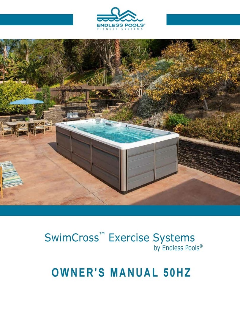
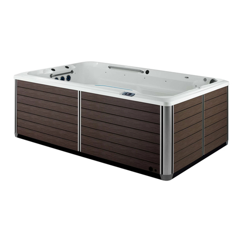
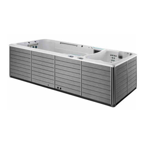
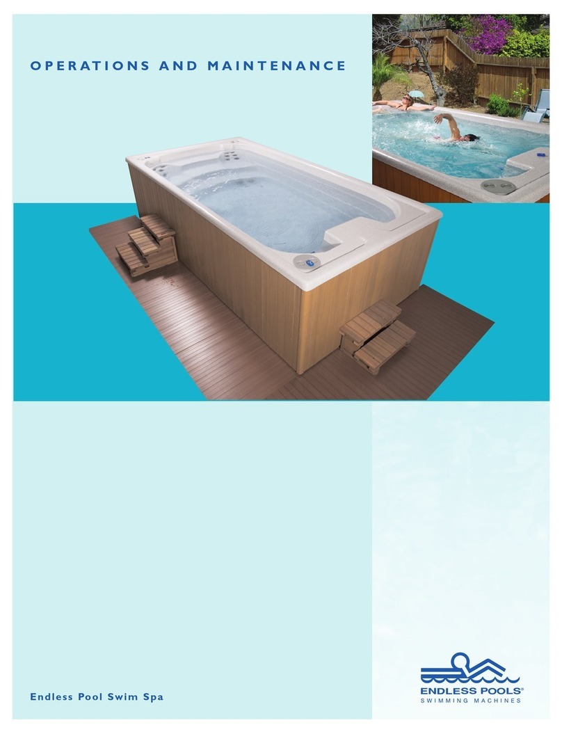
Endless Pools Pools User manual

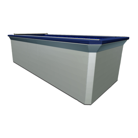
Fully Aboveground Installations
Partially In-Ground Installations
Fully In-Ground Installations
INSTALLATION INSTRUCTIONS

2
Endless Pools, Inc. provides for every aspect of an Endless Pool®project. This manual, “Installation Instructions” assists in the
installation process. This manual should be used in conjunction with other available resources including the Installation DVD or
Video which begins with a 30 minute overview followed by step-by-step instructions of an entire installation. No installer should
work on an Endless Pool installation without at least watching the 30 minute overview. We strongly encourage those involved in
the installation to watch the DVD or video before beginning work.
Additional available resources including The Introduction Booklet, The Planning Guide, and Technical Specifications are listed on
the back cover of this booklet. A series of Technical Bulletins are packaged with the Endless Pool equipment. Copies of these
Tech Bulletins are included in the Owner’s Manual and online at www.myendlesspool.com/downloads.html. These bulletins are
referenced in the following installation instructions. In addition we encourage installers to call our Customer Service Department
at (800) 910-2714 before beginning installation to register their project and sign up for weekend technical support.
Please be advised that gloves and safety goggles should be worn during the installation of an Endless Pool.
Installation Instruction Booklet Information
Installation Instructions Table of Contents
Pool Arrival and Inspection ..................................................................................................................3
Main Drain Outlet.................................................................................................................................3
Assembly of Pool Panels (Overview)...................................................................................................3
Panel Assembly Instructions ................................................................................................................3
Exploded View of Panel Assembly.......................................................................................................4
Optional Tension Straps for Flat Bottom Pools....................................................................................7
Assembly of Pool Panels with a Deeper Pool ......................................................................................8
Installation of Reinforcing Channels....................................................................................................8
Installation of the Liner Hanger............................................................................................................9
Valve Assembly.....................................................................................................................................10
Coping...................................................................................................................................................11
Options..................................................................................................................................................11
Optional Bullnose Coping System........................................................................................................11
Optional Synthetic Coping System.......................................................................................................12
Optional Aluminum Coping System.....................................................................................................12
Optional Retractable Security Cover System .......................................................................................12
Optional Solar Blanket Roll Up System...............................................................................................13
Optional Tension Straps........................................................................................................................13
Optional Hydrotherapy Jets System......................................................................................................13
Optional Underwater Lights System.....................................................................................................14
Optional Swim Current Gauge..............................................................................................................14
Optional Corner Step ............................................................................................................................14
Optional Full Depth Stair .....................................................................................................................14
Optional Swim Mirror...........................................................................................................................15
Optional Off-Peak Power......................................................................................................................15
Optional Natural Gas or Propane Gas Heater.......................................................................................15
Optional 50 Hertz Systems for International Customers .....................................................................15
Optional Insulation................................................................................................................................15
Optional Deeper Platform.....................................................................................................................16
Optional Stainless Steel Floor Structure...............................................................................................16
Felt Underlayment.................................................................................................................................16
Liner......................................................................................................................................................16
Installation of Stainless Steel Internal Components.............................................................................17
Thru-wall Connections..........................................................................................................................18
Plumbing the Pool and Water Quality System......................................................................................21
Water Quality System Electrical Connections......................................................................................22
Power Unit ............................................................................................................................................22
Bonding and Grounding........................................................................................................................22
Hydraulic Run Hoses............................................................................................................................22
Adding Hydraulic Fluid........................................................................................................................23
Start-Up and Maintenance ....................................................................................................................23

1. Pool Arrival and Inspection
The Standard Endless Pool®arrives in three packages: a skid of
6 pool panels weighing approximately 850 lbs., a 4' x 8' x 4' high
crate weighing about 1,150 lbs and a pair of 6 5/8" wide steel
reinforcing channels. Most shipping companies will lower the
containers to the ground with a hydraulic lift gate on their truck;
the pool can remain in the containers until you are ready to begin
installation. Please contact our shipping department prior to
shipment to answer any questions you may have. Since every
delivery is slightly different, and depends to a large extent on
site conditions, it is important to speak with our shipping depart-
ment well in advance to reduce the chance of surprises. Please
refer to Tech Bulletin #1 for a detailed discussion of shipping
and the choices available.
Upon arrival, the packages, see Figure 1.1, should be inspected
for external damage. Should there be visible damage, you must
complete a damage-claim report provided by the truck driver.
Please call the Endless Pools shipping department immediately
at (800) 732-8660. The pool components are not damaged by
freezing conditions and may be stored outside under a tarp for
an extended period prior to installation. See Figure 1.2.
To begin installation, or to move pool components, begin
unpacking the pool. Using a hacksaw or tin snips, remove the
steel packing straps encircling the pool panel skid. The wooden
top and sides of the crate may be removed with a phillips-head
screwdriver.
2. Main Drain Outlet
Most municipalities recognize our pool wall suction fitting as an
appropriate drain however some municipalities, notably in
Florida, may require a main drain outlet in the floor of your
pool. If you know this is a requirement the main drain needs to
be positioned prior to pouring concrete. Refer to Tech Bulletin
#16A for more information. To obtain a main drain please call
your sales person or our Customer Service Department. If you
are installing an Endless Pool on an existing concrete slab and
your municipality requires a main drain outlet in your pool floor
please call our Customer Service Department for details.
3.Assembly of Pool Panels (Overview)
Bolt the panels together as shown on the video leaving access at
the front of the pool for service. If jets, lights and/or a retractable
security cover are to be installed, outside access to additional
walls will be required. Access requirements are described in the
Technical Bulletins, Technical Specifications and in The
Endless Pool Planning Guide. Packed in the skid of panels is the
Pool Panel Hardware Kit, see Figure 3.1, that contains all of the
pieces necessary to assemble the pool panels and anchor them to
the concrete floor. Also found in the kit is Tech Bulletin #2
describing this simple assembly and a list of all the parts in the
Pool Panel Hardware Kit.
If anchoring down to the concrete is impractical and you have a
flat-bottom pool, you may have selected optional Tension
Straps. If they were ordered with the pool they would be pack-
aged in the pool crate. Instructions for their use are included in
Tech Bulletin #2.
When an Optional Deeper Endless Pool has been selected, the
panel enclosure will be anchored down to the concrete and there
will be a concrete pad with a formed deeper section inside the
panel enclosure. This is shown well in the Installation Video.
Tech Bulletin #2 also includes instructions for this type of instal-
lation and an order form for a Custom Deeper Pool Liner.
4. Panel Assembly Instructions
On a level concrete slab assemble the 6 wall panels. The smooth
wall of each panel should face inward. See Figure 4.1. The front
panel-the panel towards which you will be swimming-has cutouts
for the skimmer, drain, water-return fitting, and 2 hydraulic hoses.
Leave at least 18" of clearance from the front panel surface for the
3
Fig 1.2: Outdoor storage with tarp.
Fig 3.1: Hardware in Panel Kit.
Fig 1.1: Pool crate, panels and channels shown as they will arrive.
(1) 7', 8', 9', or 10' LONG
ACCESS PANEL
NOTE:
1. ALL PANELS ARE 14 GAUGE STEEL WITH A
2 1/2OUNCE (G235 CULVERT STOCK)
GALVANIZED COATING.
(4) 6', 7', or 8' LONG
PLAIN PANELS
(2) REINFORCING CHANNELS
11 GAUGE
6 5/8"(I.S.) x 11'-4" LG.
TOP RAIL
BASE RAIL
3'-6"
(TYP.)
Z-BRACE
3 1/2" 14 GAUGE
@ 24" ON CENTER
PER PANEL
NOTE: THESE DRAWING DIMENSIONS COMPLY WITH THE NATIONAL SPA AND
POOL INSTITUTE SUGGESTED MINIMUM STANDARDS FOR RESIDENTIAL POOLS.
FOR INFORMATION CONCERNING NSPI MINIMUM STANDARDS, WRITE: NATIONAL
SPA AND POOL INSTITUTE, 2111 EISENHOWER AVENUE, ALEXANDRIA, VA 22314
(703) 838-0083.
(1) 7', 8', 9', or 10' LONG
ACCESS PANEL
(10) GUSSETS 14 GAUGE
3 7/16" X 6 5/16" X 9 3/4"
(4) OUTSIDE SQ. CORNER
CAPS 14 GAUGE
1 1/2" X 1 1/2" X 6 7/16"
(4) OUTSIDE CORNER
ANGLES 14 GAUGE
1 1/2" X 1 1/2" X 39"
6 1/2"
EXPLODED VIEW OF PANEL ASSEMBLY
4

top 24" of the pool panel for access both during and after installa-
tion. Only 8" of clearance is required for the bottom 18" of the
front panel and 7" of clearance is required for the other 3 sides of
the pool — disregarding for the moment the requirements for
access for jets, lights, or the retractable security cover.
The 6 wall panels will form a pool enclosure with inside width
of 7' 0", 8' 0", 9' 0" or 10' 0" and inside length of 12' 0", 13' 0",
14' 0", 15' 0", or 16' 0" depending on the pool size selected. Each
panel has a 3-1/2" bottom flange and a 6-1/2" top flange.
Consequently, the outside bottom dimensions of the pool are 7"
greater than the inside dimensions and the outside top dimen-
sions are 13" greater than the inside dimensions.
On the long sides, the end flanges of the 2 adjoining panels bolt
together directly. See Figure 4.2. The 4 corners of the pool are
held together by 4 outside corner angles each 39" long. See
Figures 4.3 and 4.4. Install the 10 gussets at every panel inter-
section—1 on each side, see figure 4.2, and 2 in each of the 4
corners, see Figures 4.3 and 4.4. Do not install these gussets
between the panels. Install the 4 top corner angles in each of the
4 corners. See Figures 4.3 and 4.4. Loosely bolt together the
entire enclosure, see Figures 4.5 and 4.6, then check that the top
flange of each panel is flush with its neighboring panel before
tightening the bolts. Check that the panels come together even-
ly at the corners. There is some play in the bolt holes to allow for
adjustment.
Fig 4.2: Long side end flanges bolted together with a gusset.
Fig 4.4: Loosely bolt together the corner angle, top corner angle, gusset and panel.
Fig 4.1: Pool Panel and Hardware Kit.
Fig 4.3: Outside corner angle, top corner angle, gusset and panel end flange shown.
Gusset
Outside
Corner Angle
Top
Corner
Angle
End Flange
Fig 4.5: Completing pool enclosure. Note cut-outs on front panel.
Fig 4.6: Bolting the pool enclosure together. Note cut-outs on front panel.
5

If the pool is to be positioned next to a wall some bolts will be
hard to reach. In this case, one side may be bolted together first
and then slid back against the wall. You will probably want to
use blocking angle rather than anchor bolts for this inaccessible
condition. See Figures 4.7 and 4.8. The use of these angles is
shown in the video and is described in Tech Bulletin #2. Take
care when sliding the enclosure against a wall to leave enough
room for the coping and for the 18" of access at the front. If rigid
foam insulation is to be applied on the walls of the pool, which
is recommended, be sure to install it before sliding the enclosure
against the wall. See Figures 4.9 and 4.10. Once the panels are
bolted together to form the pool enclosure make sure that the
enclosure is square. First check that the long walls made from 2
panels are straight. Then measure both diagonals. See Figure
4.11. Shift the panels by pushing at the corners until the differ-
ence is less than 1/8".
Care should be taken to ensure that the pool is square before
securing the panels to the concrete. The bottom flange of each
panel has pre-drilled holes to accept the 3/8" x 3" anchor bolts
provided. See Figures 4.12 and 4.13. An absolute minimum of
10 anchor bolts are required as described in the Installation
Video. See Figure 4.14. When possible more anchor bolts
should be used with an emphasis on the centers of the panels and
the center of the long sides of the pool enclosure. See Tech
Bulletin #2, page 2 for anchoring information. Now insulate the
Fig 4.8: Blocking angle installed with pool panel pushed flush against it.
Fig 4.9: Measure and cut rigid foam insulation to fit between support struts.
Fig 4.10: Rigid foam insulation being installed between the support struts.
Fig 4.11: Checking the pool for square.
Fig 4.12: Drilling to secure anchor bolts.
Fig 4.7: Drilling through foundation to secure blocking angle.
6

remaining pool walls with rigid foam insulation. See Figure 4.9
and 4.10. We would strongly recommend insulating the walls of
the pool. Please note that the insulation boards should not be
used under the pool as the anchoring system will be compro-
mised. Insulation under the pool has only a marginal value, as
the heat transfered is not lost. If you wish, with new construc-
tion, you may lay down rigid foam insulation prior to pouring
the concrete slab.
5. Optional Tension Straps for Flat Bottom Pools
When the deeper pool option has not been selected and it is
desired not to drill into the concrete floor, Tension Straps may
be used. See Figure 5.1. These are ordered from Endless Pools,
Inc. for any size pool. The kit for a standard 7' x 14' pool con-
sists of 4 stainless steel tension straps, 1 long (14' 7") and 3
short (7' 7"). These straps run under the bottom flanges and
along the floor, connecting to the outside lips of the flanges on
each side (Tech Bulletin #2, page 3). See Figure 5.2. They are
designed to resist the hydrostatic force of the water in the pool.
Assemble the panels as described above placing the Tension
Straps under the bottom flange. The vertical lip of the bottom
flange of each panel has pre-punched holes to accept the 3/8"
nuts and bolts which are used to secure the tension straps. See
Figure 5.3. This is the same hardware used to bolt the panel
enclosure together. The Tension Straps should connect between
the centers of opposite panels and at the joint in the long walls.
Tighten the nuts and bolts securing the tension straps before
sliding the pool into a corner. See Figure 5.4. If a strap bows up
check the dimension of the pool enclosure at the bottom as the
panels may be bowed in. If necessary, you may loosen a tension
strap bolt on the accessible end of one tension strap and pull the
strap taut. Be sure to keep the nut and bolt in place and tighten
them as you fill with water and the panels push outward.
Fig 4.13:Anchor bolts installed securing pool panel to the foundation.
Fig 5.1: Optional tension straps.
Fig 5.3: Connecting pool bottom outside flange and tension strap.
Fig 5.2:Tension straps in place under pool.
MINIMUM ANCHORING PLAN
Fig 4.14: Minimum anchor bolt placement.
7

6.Assembly of Pool Panels with a Deeper Pool
When the deeper pool option has been selected, tension straps
cannot be used. The anchor bolts provided with every kit must
be used for these installations. They secure the panels to the
concrete through the holes in the bottom flanges of the panels.
See Figures 6.1 and 6.2. Ensure that the pool is square before
securing the panels to the concrete. Also be sure that an ade-
quate shelf is present on each side and at the front and back for
the stainless steel benches which will be installed later. If an
Optional Full-Depth Stair has been ordered the shelf the last step
lands on must be at least 60". See further discussion of this in
“Optional Full-Depth Stair,” Section 22 and in Tech Bulletin #10.
The bottom flange of each panel has pre-drilled holes
to accept the 3/8" x 3" anchor bolts provided. See Figures 6.1
and 6.2. An absolute minimum of 10 anchor bolts are required
as described in the Installation Video. See figure 6.3. When pos-
sible more anchor bolts should be used with an emphasis on the
centers of the panels and the center of the long sides of the pool
enclosure. See Tech Bulletin #2, page 2 for anchoring informa-
tion.With the deeper area pool, it is critical that the panel enclo-
sure be installed correctly so that your custom liner will fit.
Please refer to Tech Bulletin #2 for details of the deeper area.
EPI will make a liner only after receiving a completed copy of
the Liner Order Form which is typically filled out once the pan-
els are installed. This Order Form should be completed in full
and faxed to EPI Customer Service at 610 497 8693. Allow 3
weeks for delivery of the custom liner. While awaiting the cus-
tom liner the installation and finish work may proceed.
7. Installation of Reinforcing Channels
The 2 channels, each 6 5/8" wide, fit over the top flanges of the
two long sides of the pool. The channels bridge the joint
between the panels on the long walls. Check that the enclosure
is square. Put the channels on loosely. See Figure 7.1. Check to
see if either channel has a sharp edge or burr and be sure to
locate this on the outside face of the pool or file it down and/or
cover the sharp edge securely with duct tape. The channels will
be secured down later with the self-drilling fasteners provided
in the liner hanger kit. These channels are structural and must be
installed correctly to withstand the hydrostatic load. If you have
Fig 6.1: Drilling through foundation to secure anchor bolts.
Fig 7.1: Installing the structural channels.
Fig 6.2:Anchor bolts installed securing pool panel to the foundation.
MINIMUM ANCHORING PLAN
Fig 6.3: Minimum anchor bolt placement.
Fig 5.4:Tightening the tension strap bolts.
8

any questions regarding these channels or their placement,
please call Customer Service.
When possible, the walls of an Endless Pool®should be braced
laterally before filling with water to reduce outward deflection
when the pool is filled with water. The steel reinforcing chan-
nels supplied by Endless Pools Inc. are sufficient to withstand
the hydrostatic load but the pool walls will deflect slightly with-
out bracing. When a rigid coping such as tile is planned this
deflection is undesirable. For in-ground or partially in-ground
Endless Pools simply brace or shim laterally back to the walls
of the pit before filling. Be sure not to brace back to a load-bear-
ing wall unable to resist this lateral load. Please call Endless
Pools Customer Service with any questions.
8. Installation of the Liner Hanger
The aluminum liner hanger installs around the perimeter of the
pool panel enclosure. The liner literally hangs from this extru-
sion using a bead that is heat welded into the top edge of the
liner. The liner hanger system is packaged in the pool crate in a
long, triangular-shaped box. See Figure 8.1. The pieces are pre-
cut and pre-mitered to fit your pool. Only one long piece on
each side needs to be trimmed to length. Self-drilling fasteners
are included in the kit along with a nut driver attachment for
your drill.
If you have purchased the optional 8" Aluminum Coping, which
has a liner hanger built into it, please refer to Section 14 and
Technical Bulletin #4B prior to proceeding with your assembly.
If you have purchased the optional Bullnose Coping,
which has a liner hanger built into it, please refer to Section 12
prior to proceeding with your assembly.
Install the 4 triangular inside corner supports, using the self-
drilling fasteners provided. See Figure 8.2. Then lay out the
entire system around the inside perimeter of the pool. The hang-
er pieces should be flush with the inside of the reinforcing chan-
nel and will protrude into the pool the thickness of the channel
everywhere else. This is shown particularly well on the
Installation Video. Because the height of the 2 reinforcing chan-
nels is slightly higher than the surrounding top flange, EPI pro-
vides 1/8" thick washers in the Pool Panel Hardware Kit to
place under the liner hanger and shim the pieces up to the level
Fig 8.1:Triangular liner hanger box.
Fig 8.3: 1/8" washer shims for leveling liner hanger.
Fig 8.4: Short mitered liner hanger attached to the triangular inside corner supports.
Fig 8.5: Caulking the liner hanger on the top.Fig 8.2: Installing the triangular inside corner supports.
9

of the channels to keep the whole system level. See Figure
8.3. At the 4 corners, the short mitered pieces of liner hanger
rest on 4 triangular inside corner supports. Once the entire
system is laid out satisfactorily secure it down to the top
flange through the pre-drilled holes in the liner hanger. See
Figure 8.4. Over the channels, these fasteners should be
drilled through the channel and the flange. You may use a
pilot hole if you wish. Elsewhere, the fasteners must be drilled
through the washers and the panel flange.
Caulk the gap between the liner hanger and the panel to ensure
that no water falling on the top flange of the pool panel can work
its way down behind the liner. See Figures 8.5 and 8.6. (With the
same objective in mind, later caulk the joint between the top of
the liner hanger and the coping that you install over the entire
top flange of the pool.)
9.Valve Assembly
If
you have purchased the optional Aluminum Coping,
please refer to Section 14 and Technical Bulletin #4B prior
to proceeding with your assembly.
The Valve Assembly is included in a padded bag, found in
the System Control Board box, with the thru-wall fittings to
be installed on the front wall of the pool. See Figure 9.1.
Attach the Valve Assembly to the top flange of the front
panel as shown in the video. This valve controls the amount
of hydraulic fluid reaching the hydraulic motor, thereby
determining the speed of the water current. The Valve
Assembly is attached to the pool with self-drilling fasten-
ers, using the nut-driver bit provided. See Figure 9.2. Tech
Bulletin #3 explains all of the front panel connections
including these hydraulic connections in detail; the Tech
Bulletin is included in that padded bag.
Remove the knob and shaft extension by loosening the
5/64" allen screw in the coupling. See Figure 9.3. Place the
Valve Assembly and rubber pad provided over the top
flange of the pool wall (aligning the hole in the Valve
Mounting Bracket with the small hole in the flange). See
Figure 9.4. Secure with 2 self-drilling screws. See Figure
9.5. Slip the shaft back through the holes and reattach.
Fig 8.6: Caulking the liner hanger on the bottom.
Fig 9.3: Remove the knob and shaft extension.
Fig 9.2:Valve assembly attached to pool wall.
Fig 9.1: Front Panel Connections padded bag with Valve Assembly. Fig 9.4:Align the hole in the valve bracket with the small hole in the panel.
10

Retain the knob, and after mounting your coping reattach
with the 1/8" allen wrench provided. Retain these 2 allen
wrenches for future use. Note: Endless Pools, Inc. has pro-
vided a shaft long enough for most coping systems. The
installer should cut down this shaft so that the knob is close
to the coping. See Figures 9.6 and 9.7.
Typically, the Valve Assembly is mounted in the center of
the front panel. The hydraulic hoses connected to the sub-
merged hydraulic motor in the pool are sufficiently long,
however, to move this valve off-center. Care should be
taken when closing in the front of the pool to leave access
to these hoses and the Valve Assembly and make certain
that no carpentry is touching the hoses. Use short lengths of
pipe insulation to keep the hoses from touching carpentry
and resonating. Please refer to Technical Bulletin #3A.
10. Coping
Once the liner hanger system is installed you can proceed with
the installation of a coping system. By coping we mean any
protective material that finishes off the top perimeter of the
Endless Pool. The galvanized steel pool panels should not be
left unfinished. The coping system that you select directly
influences the appearance of the pool. Different alternatives
are described in our Technical Specifications under Finishing
Details in section 5. We also offer as options three alternative
coping systems which are described below. The liner hanger
system allows you to install the liner and internal equipment
after the coping is in place. Since it is best not to undertake
coping installation and a variety of external carpentry and fin-
ishing tasks with the pool filled with water, many people
choose to do that work now.
11. Options
An Endless Pool®is usually customized to meet the needs of the
end user. Pools of different lengths and widths are selected as
well as deeper pools as described previously. Naturally, the
installation will vary depending on the options selected so it is
important to understand exactly what has been supplied. When
options are sent, installation instructions are included in the
package. These instructions include information from the man-
ufacturer when relevant, and a Tech Bulletin from Endless
Pools, Inc. Each of the options is also discussed more fully in
the Planning Guide which was used by the customer during dis-
cussions with the Endless Pools, Inc. design professional.
Below is a summary description of the available options and
important installation considerations. Please review this section
before proceeding with the installation to ensure that selected
options have been considered.
12. Optional Bullnose Coping System
Typically used when the pool is installed fully in-ground, the
Optional Bullnose Coping System allows the installer to finish
with concrete and/or tile right up to the water’s edge. The alu-
minum bullnose coping system acts as both a liner hanger and a
finished edge. Endless Pools, Inc. supplies precut pieces to fit
Fig 9.7:Trim the valve shaft so the control knob will be flush with the coping. Fig 12.1: Optional Bullnose coping system.
Fig 9.6: Once coping system is installed trim the valve shaft so the knob is flush.
Fig 9.5: Secure the valve assembly with self-drilling screws.
11

the specific pool size ordered. Included in the kit are radius cor-
ners and straight pieces to provide a finished look. These extru-
sions are fastened down to the top flange of the pool panels
through the spacer washers and the reinforcing channels in the
same fashion as the regular liner hanger system. See Figure 12.1
Please review Technical Specification 5.3 before installing this
system. The installer is responsible for building a proper
perimeter substrate for the concrete or tile.
13. Optional Synthetic Coping System
An ideal solution for indoor installations, the Synthetic Coping
System finishes off an Endless Pool®quickly and easily.
Typically used when the pool is installed partially or fully
aboveground, the Optional Synthetic Coping System provides a
finished 9-3/4” wide waterproof edge to your pool. Made of
synthetic boards and corner pieces with shiplapped joints, the
system comes in a variety of colors. See Figure 13.1. The sys-
tem is described more fully in Tech Bulletin #4. The appearance
of the joint and the fastening system is best described in the
“Full-Length Installation” Video.
14. Optional Aluminum Coping System
The Endless Pools Aluminum Coping Option offers a conven-
ient method to finish off the top edge of your Endless Pool,
either indoors or out. The coping, which also acts as a liner
hanger, is 1-3/8" thick and comes in a sand textured white fin-
ish. The pieces are precut to fit your pool size and fit securely
over the steel channel. The system is described more fully in
Tech Bulletin #4B. The coping system is delivered with your
pool. It may be ordered later and shipped by UPS groundtrack
for an additional shipping charge. The kit’s weight depends on
the pool size and comes in 5 boxes.
Each coping kit contains pre-fabricated corners and straight
aluminum pieces cut to match your pool size. The 8" wide pro-
file of the coping makes it ideally suited for pools which are
freestanding or partially recessed. The coping is secured to the
top of the wall panel with tek screws, see Figure 14.1, which
are concealed beneath the aluminum snap strip of the same
finish as the coping. See Figure 14.2. As an alternative the 6-
3/8" snap strip can be eliminated and a 6" accent tile can be
installed. Joints between the adjacent coping pieces are cov-
ered with an aluminum cover strip with the same finish as the
coping. See Figure 14.3.
15. Optional Retractable Security Cover System
Our most popular option and strongly recommended, the
Retractable Security Cover system protects children and pets
from the pool while keeping in temperature and humidity. With
some installations, suitable access for this roll up cover system
is complex and should be discussed with an Endless Pool design
professional during the planning stage. Tech Bulletin #5
describes the cover installation more fully and includes an order
form to select the appropriate cover fabric and specify indoor or
outdoor installations which in turn determines whether a rain-
water removal pump is supplied as part of the kit.
Fig 13.1: Synthetic coping system. (Sandstone shown)
Fig 14.1: Securing aluminum coping system with tek screws.
Fig 14.2 Installing the aluminum coping snap strip.
Fig 14.3: Installing the aluminum cover strip.
12

Typically the cover rolls off the rear of the pool as shown in
the video. Other alternatives are possible if space is limited.
These are discussed in more detail in Tech Bulletin #5. The kit
includes the roller mechanism for the width of pool purchased,
appropriate lengths of track, an aluminum leading edge, and the
rugged fabric which floats on the water surface suspended
between the parallel tracks. Two steel brackets to mount the
roller mechanism at one end of the pool are available.
See Figure 15.1.
The optional Retractable Security Cover system is manually
powered. We believe that this system is optimal for our
compact pool and when installed correctly provides a simple
means of covering the pool. Automated systems are also
available. If you wish to automate your system call
our Customer Service Department and they can provide
additional information.
The aluminum track on either side of the pool is a requirement
of the retractable security cover option. See Figure 15.2.
Covering this track is possible but increases complexity
and will add to the cost of installation. Call Customer Service
for details.
16. Optional Solar Blanket Roll Up System
Endless Pools, Inc. supplies an 8' x 16' Solar Blanket for
all Endless Pool sizes. This may serve as a temporary cover
while the retractable security cover is being installed. For those
who wish it to serve as a more permanent cover, a simple
PVC pipe may be used to roll up the blanket for storage when
the pool is in use. For this purpose, we supply PVC clips and
PVC pipe long enough for your pool width. Depending on
the width of the pool the PVC pipe will come in one or two
pieces with a coupling attached to one end of the one piece of
pipe. Using the PVC cleaner and PVC cement you received in
your plumbing kit, glue the second piece of pipe into the open
end of the coupling. For pools larger than 8' x 16' a larger solar
blanket is available by request and shipped via UPS.
Alternatively, the roller mechanism from the retractable
security cover may be used in conjunction with a length of 3"
diameter PVC pipe to roll up the blanket. This optional solar
blanket roll up system is available from the Endless Pools, Inc.
Customer Service Department.
17. Optional Tension Straps
If you do not wish to anchor the pool panels down with the 3/8"
x 3" anchor bolts provided, the optional Tension Straps may be
used (see previous installation instructions). They must be
selected in advance and when included they will be shipped in
the pool crate. Regular 3/8" nuts and bolts used to bolt together
the pool enclosure may be used to secure the Tension Straps to
the bottom flange of the pool panel. Installation using these
straps is described more fully in Tech Bulletin #2, page 3.
18. Optional Hydrotherapy Jets System
By providing a supplementary pump and controller and plumb-
ing one suction and four venturi-type jets through the wall of an
Endless Pool, the user can enjoy the therapy benefits of jets in
addition to the variable speed swim current. See Figure 18.1.
Installation is relatively straightforward but roughly doubles the
plumbing work required. The kit provided by Endless Pools Inc,
includes everything necessary with the exception of the 1-1/2"
schedule 40 PVC pipe. Detailed instructions are included in
Tech Bulletin #6 along with a typical layout drawing. When jets
are installed it is important to leave access to the outside of the
pool panel for service. The five holes for the jets should be cut
Fig 15.1: Retractable security cover brackets.
Fig 18.1: Optional hydrotherapy jet kit.
Fig 15.2: Retractable security cover track (on aluminum coping).
13

before installing the liner. See Figure 18.2. The hole for suction
from the pool for the jets should be cut 4" below the three inline
thru-walls on the front panel. If the pool is located outdoors
where freezing is an issue, care must be taken with the jet sys-
tem plumbing. The freeze control option should be considered
under these conditions. Call Customer Service with any ques-
tions about this limitation.
19. Optional Underwater Lights System
Underwater Lights are an important aesthetic option. Typically
located on either the side or the end wall of the pool, these two
lights thread into in niches that are installed after the liner is
in place. The holes for these niches are cut using the holesaw
provided before the felt and the liner are installed. See Figure
19.1. Directions come with the lights which are packaged in the
pool crate. See Figure 19.2. These directions are also found in
Tech Bulletin #7B. These lights must be installed in accordance
with local electrical codes by a licensed electrician. Each light
consists of a dry niche which serves as a porthole. The low-volt-
age light threads into this porthole outside the pool. For outdoor
installations a weather resistant can is provided for added pro-
tection. A 50' cord connects this light to a transformer which in
turn plugs into a switched GFI outlet.
20. Optional Swim Current Gauge
The speed of the swim current in an Endless Pool®is a function
of hydraulic pressure. This pressure can be read using the gauge
on the power unit. Alternatively, the optional Swim Current
Gauge may be plumbed into the high pressure hydraulic line
and the pressure may be read poolside in PSI (Pounds per
Square Inch). See Figure 20.1. This pressure will correlate with
swim current speed. The correlation, however, is inexact and
will change as the hydraulic fluid heats up. Pressure is a good
way to set the repeatable speed of the machine. A simple alter-
native is to use the position of the blue speed control knob. The
plumbing of the optional Swim Current Gauge is described in
Tech Bulletin #8.
21. Optional Corner Step
To assist with access to the Endless Pool, optional
stainless steel Corner Steps are available inside the Endless Pool
in any of the four corners. For a more complete discussion of
access to an Endless Pool please refer to the Planning Guide.
These optional steps are approximately 11" high and are secured
to the internal stainless steel bench/water return system. They
are easily installed using a phillips screwdriver. If you wish to
order them after the pool has shipped, contact the Customer
Service Department and they will ship one to the address pro-
vided. The optional Corner Step is described more fully in Tech
Bulletin #9. A 6" high Corner Step is also available.
22. Optional Full Depth Stair
For those needing an easier route into the pool our optional Full
Depth Stair provides seven low-rise steps and a handrail.
Typically installed with fully in-ground Endless Pools, the Full
Fig 18.2: Cutting holes for optional hydrotherapy jets.
Fig 20.1: Optional speed control gauge.
Fig 19.1: Cutting holes for optional underwater lights.
Fig 19.2: Underwater light package with instructions.
14

Depth Stair allows the user to gradually enter the water from
deck height. The steps do not obstruct the swim current. The
Full Depth Stair takes the swimmer down to the bottom of the
stainless steel benches. If an optional deeper pool has been
selected, you would step from the bottom of the stair down into
the deeper area. Care must be taken to ensure that the shelf on
which the Full Depth Stair rests is sufficiently large. The shelf
must extend 60" from the end wall where the steps are located.
Details of this design should be worked out in advance with an
Endless Pools design professional. The optional Full Depth
Stair is described more fully in Tech Bulletin #10. The Full
Depth stair should be ordered with the pool to avoid substantial
additional freight charges due to the size and weight of the box
needed to ship the steps.
23. Optional Swim Mirror
The Swim Mirror helps with stroke technique and makes your
swimming workout fun. The Swim Mirror, described more fully
in Tech Bulletin #11, is made from durable stainless steel and is
attached with three stainless steel screws which are already
attached to the housing just below the swim propulsion
housing. When a deeper pool is selected, make sure that the
shallower area extends at least 13" beyond the front bench to
accommodate the Swim Mirror. Swim Mirrors are easily sent by
UPS ground and may be ordered later.
24. Optional Off-Peak Power Meter
The Endless Pool®Kit comes standard with a 5.5 KW electric
heater. Whenever possible, a special Off-Peak Power Meter
should be installed to power this heater. Many power companies
offer special rates for off-peak power, often less than half the cost
of regular power. Check with your local power company for
availability. The few hundred dollar installation charge is more
than offset by the lower cost for electricity. Since the heater turns
on only when the 24 hour time clock turns on the circulating
pump it is not a handicap to only have off-peak power available
at certain times of the day. It is common with off-peak power to
run the filtration and heating equipment at night. Ask your power
company and your electrician about this useful option.
25. Optional Natural Gas or Propane Gas Heater
When Natural Gas or Propane Gas is available, a Natural Gas
or Propane Gas Heater is usually a less expensive alternative
for heating the pool. To properly consider this option,
review the owners manual describing the Raypak 50,000
BTU Electronic Ignition Natural Gas or Propane Gas Heater
available from Endless Pools Inc. This manual is included in
its entirety in Tech Bulletin #12. The Heater comes with
stainless steel heat sinks and either an indoor or an outdoor
draft hood. When reviewing the manual, pay close attention
to rules dictating minimum clearances to combustible surfaces
and the requirements for proper venting for safety. The heater
must be installed by a licensed plumber. If your installation
elevation is greater than 2,000 feet please call our Customer
Service Department to ensure that you have received a special
high-elevation gas heater. Do not install a standard heater
at higher elevations or sooting may occur.
26. Optional 50 Hertz Systems for
International Customers
International customers interested in installing an Endless Pool
where 50 Hertz power is available can specify this equipment
prior to shipment. Both the Hydraulic Power Unit and the
Circulating Pump come in 50 Hertz configurations. Please
review Tech Bulletin #13 for a description of available alternate
equipment for international customers. Please note: Endless
Pools, Inc. makes no representations as to the suitability of our
equipment abroad. We have not applied for relevant interna-
tional certification and such certification may be required. Local
permitting is the sole responsibility of the buyer.
27. Optional Insulation (by others)
To conserve heat and reduce operating costs we strongly rec-
ommend that the Endless Pool be insulated with rigid foam. See
Figures 27.1 and 27.2. Simple 2" thick rigid foam insulation
boards are usually adequate and are available from any building
supply house. Check with your supplier for a recommended
adhesive appropriate for the type of rigid insulation that they
supply. If the pool is to be installed outside in a cold climate,
you might consider using two layers. Be sure to consider the
danger of freezing for any pipes running outside the insulation.
Fig 27.2: Rigid foam insulation being installed between the support struts.
Fig 27.1: Measure and cut rigid foam insulation to fit between support struts.
15

28. Optional Deeper Platform
Sometimes customers desire a deeper pool completely above-
ground without excavation. This can be done by constructing a
wooden platform using a drawing supplied by Endless Pools,
Inc. This system is described in Tech Bulletin #14. This solution
only applies to platforms that are 12" or less in height. Any plat-
form of greater height should be designed by a local engineer.
Endless Pools, Inc. can not take responsibility for the structural
integrity of platforms constructed by others.Also note that deep-
er pools hold more water and exert a greater load on the floor
upon which they rest. Endless Pools, either deeper or flat bot-
tomed, should not be built on upper stories without a structural
engineer involved who is willing to stamp the drawings.
29. Optional Stainless Steel Floor Structure
The Endless Pools, Inc. optional stainless steel floor structure
provides a simple cost effective alternative to a poured concrete
floor system. This system is an appropriate alternative if access
to your pool site is a problem for concrete trucks or the distance
is too great to haul concrete. Built to fit your specific pool size,
the stainless steel floor system can be used for flat bottom or
deeper pools. This system has been engineered to withstand the
weight of the pool for pool configurations that are partially in-
ground or fully above ground. The stainless steel has a foam
backing providing added insulation for your pool. Minimal
excavation is needed for above ground or partially in-ground
pools, making this the ideal solution for a speedy installation.
It is delivered with your pool as a kit of parts, which are
assembled on site. Refer to Tech Bulletin #14A for step by step
installation instructions.
30. Felt Underlayment
If it is possible, finish the rest of the pool area, especially the
ceiling over the pool, before proceeding. This will help ensure
that the liner is not damaged, and also keep the pool water, skim-
mer, and filter free of construction debris.
Vacuum the pool floor carefully, and make sure there are no
sharp bumps that might damage the liner. Take special care to
remove any metal chips that may have fallen on the floor. Install
the protective felt underlayment on the floor of the pool. The felt
kit comes in a box with the four foam corners, a can of spray
adhesive and Tech Bulletin #15. See Figure 30.1. The felt is 7' x
16'. For wider pools cut pieces as appropriate to cover the floor
of the pool. Place seams near the walls of the pool, so that they
will be covered by the stainless steel benches. Secure the felt to
the floor with the spray adhesive provided. See Figure 30.2.
With deeper pool installations and larger pools, a second and
sometimes even a third box of felt has been provided. Secure the
felt to the bottom and walls of the deeper area as well as to the
floor of the pool. Do not attach felt to the steel walls of the pool.
Secure the foam inserts in the 4 corners at the bottom. See
Figure 30.3. Foam corners are not installed in the 4 corners of
the deeper section of a deeper pool.
31. Liner
Standard flat bottom pool liners are usually packaged in a
cardboard box in the pool crate. Liners for deeper pools and cus-
tom-sized pools are sent separately by UPS Ground. Check to
see if your liner was backordered at the time of shipment. If you
have any questions call Customer Service about the status of
your liner.
All work around your pool should be completed before you
install your liner. Take a moment to be sure you have all neces-
sary work completed. Prepare for the liner installation. Be sure
that the liner hanger, corners, panel joints and panel to base
material are sealed with silicone. Tape off all holes in the pool
wall (lights, jets and front panel holes) from the outside. Place a
vacuum hose through the skimmer hole and tape off the skim-
mer hole. Figures 31.1 and 31.2. The hose should be 3" – 4" off
of the bottom of the pool floor felt. Install the liner by starting at
the center of the front panel.
Fig 30.1: Felt kit with foam corners.
Fig 30.2: Installing felt with spray adhesive.
Fig 30.3: Secure the foam corner inserts with spray adhesive.
16

Spread the liner in the pool enclosure. See Figure 31.3. Shoes
should be removed for this and all future work in the pool to
avoid damaging the liner. Find the vertical seam in the liner and
center it at the front of the pool as described in the video. See
Figure 31.4. Place the four bottom corners of the liner in the
four corners of the pool. While standing in one corner, fit the
top bead of the liner into the slot in the liner hanger. See Figure
31.5. Work your way around the pool, fitting the bead evenly
into the hanger. We recommend not ending in a corner. Smooth
the liner on the floor, pushing any wrinkles toward the walls.
After verifying that the vacuum hose is off of the bottom, turn
the vacuum on. When the liner is drawn back, check to see that
the corners are positioned properly. If not, turn the vacuum off
and reposition the liner. With the vacuum running, smooth out
all of the wrinkles. When you are satisfied with the placement
of the liner, start to fill with water.
Keep the vacuum running until there is about 6" of water in the
shallowest portion of the pool. Turn the vacuum off and remove
all tape and the vacuum hose. Continue building the interior
stainless steel portion of the pool as outlined in the Owner’s
Manual installation instructions.
Included in the box with the liner are No Diving signs. Please
post these in prominent locations around the pool. The Endless
Pool is shallow and must never be used for diving. Diving into
the pool is a very serious hazard and these stickers are intended
to warn children of the risks. Naturally, adult supervision is also
critical whenever children use the pool.
32. Installation of Stainless Steel
Internal Components
Remove the stainless steel front propulsion assembly from
the pool crate.Attach the 2 PVC corner turning vane assemblies
labeled Front Right and Front Left using the stainless steel
10/32 phillips head screws provided. These PVC turning vane
assemblies are pre-drilled. Peel off all of the protective white
plastic from the stainless steel. Lower the front propulsion
Fig 31.1:Tape off all thru-wall holes and place vacuum hose through skimmer.
Fig 31.2:Vacuum in place before liner is hung. Note thru-wall holes are sealed.
Fig 31.3: Spread out the liner inside the pool enclosure.
Fig 31.4: Find the vertical seam and center it in the front of the pool enclosure.
Fig 31.5: Inserting the liner in the corner of the liner hanger.
17

assembly into the front of the pool as shown on the video taking
care to keep the hose ends from getting wet. Two people can
accomplish this if they work carefully in stages. Be careful not
to catch the liner. Carefully slide the assembly all the way to the
front of the pool and make sure it is centered left to right.
Peel off all of the protective white plastic from the stainless steel
side benches and install them inside the pool using the side sup-
ports at the junction between two benches. See Figure 32.1. On
the two benches at the rear of the pool include the Rear Left and
Rear Right corner assemblies.
Peel off all of the protective white plastic from the stainless steel
rear bench assembly with the perforated grill. Attach the rear
base middle support to the perforated rear base using the two
stainless steel 10/32 screws on top and one 10/32 stainless steel
screw and nut provided with this plastic support. See Figure
32.2. Lower this assembly into the rear of the pool as shown on
the video.
Keep all screws loose until you have started all the screws.
Focus first on the bottom screws as they are difficult to work on
once the holes are covered with water. If you use a cordless
screw gun as shown on the video take care not to over tighten
the screw into the PVC. Be careful to inspect for burrs while
installing these screws. If a burr occurs remove the screw and
discard. We have supplied extra screws.
Do not try to install the stainless steel corner covers or any
optional corner steps at this time. They may fit tightly against
the liner in the corners and you risk cutting the liner. Put them
aside for the moment. They should not be installed until more
water is in the pool which will push the liner back in the corners.
Once the stainless steel is in and the holes are lining up, you may
continue filling the pool while you work. Stop filling three inch-
es below the lowest thru-wall connection. Once all the screws
are tight, secure the front housing with the grab bar back against
the steel wall of the pool using the special corrosion resistant
self-drilling fasteners provided. Use only stainless steel, self
drilling fasteners provided. Do not use Tek screws which will rust.
See Figure 32.3.
33.Thru-wall Connections
Once the water level is three inches below the lowest thru-wall
fitting, cut 3 round holes in the liner using the holes through the
steel as a template and a utility knife as shown in the video. See
Figure 33.1. If optional hydrotherapy jets (Tech Bulletin #6) or
underwater lights (Tech Bulletin #7) were selected you must
also cut these holes in the liner as well and plumb the jets sys-
tem and/or install the light niches. Located in the same padded
bag with the valve assembly are 2 round thru-wall fittings.
Install both of these as shown on the video. One fitting takes
water from the pool and is under suction and the other one
returns water to the pool after filtering, heating, and purifying.
The suction port is the lowest of the three inline prepunched
holes. See Figure 33.2. The return fitting is on the other side of
the housing (the left side as you face the propulsion assembly
from inside the pool). See Figure 33.3
Fig 32.3:Attaching the front housing to the pool wall.
Fig 32.1: Installing the side supports
Fig 32.2:Attaching the 10/32" screw and nut. Fig 33.1: Cut the thru-wall holes through the liner using the steel as a template.
18

Each of the thru-wall fittings has two rubber washers and one
cork gasket. One rubber washer is placed between the liner and
the steel wall of the pool. See Figure 33.4. One rubber washer
is placed between the fitting and the liner inside the pool. See
Figure 33.5. The cork gasket is placed outside the pool under
the large hex nut that holds the fitting to the wall. See Figure
33.6. This nut should be tightened hand tight.
Ultimately, the return fitting will have an eyeball fitting
installed. See Figure 33.7. For the moment you may replace the
eyeball fitting with a threaded plug with O-ring on the inside of
the pool. The suction fitting needs to have both a small adapter
and round strainer screwed into it to eliminate the hazards of
suction at this fitting. See Figure 33.8. The safety strainer fitting
is loosely installed for shipment. For the moment you may
replace the round safety strainer fitting with a threaded plug
with O-ring. This will allow you to continue filling the pool
before completing the plumbing of the Water Quality System.
Before starting up be sure to remove these plugs and replace
them with the appropriate threaded pieces.
Above the suction thru-wall are two thru-walls for two
hydraulic hoses. The thru-wall assembly is pretightened on each
hose with the appropriate amount of teflon sealant. Simply
remove the hex nut, cork gasket and one rubber washer from
each fitting and install them through the wall of the pool, as
Fig 33.2: Facing the propulsion assembly, the suction port is on the right side.
Fig 33.4: Installing the eyeball fitting into the return fitting.
Fig 33.5: Installing the suction fitting with the strainer attached.
Fig 33.6: Install one rubber washer between the liner and the pool wall.
Fig 33.7: Install the second rubber washer between the fitting and the liner.
Fig 33.3: Facing the propulsion assembly, the return fitting is on the left side.
19

done with the previous thru-wall fittings. See Figure 33.9. Hand
tighten the large hex nut and connect the hydraulic elbow fit-
tings to the top of the valve assembly as shown in the drawing
accompanying the valve assembly. See Figures 33.10 and 33.11.
You may continue to fill the pool to a point three inches below
the bottom of the skimmer opening. In the unlikely event that
any of these fittings drips call Customer Service. Do not apply
a wrench to any of these fittings without first calling Customer
Service.
The final opening on the front panel is the rectangular opening for
the skimmer. See Figure 33.12. The skimmer will be plumbed to
the suction fitting as shown in Tech Bulletin #3 in order to reduce
the suction hazard and protect the pump in the event that the sys-
tem is kept on with the water low. The final protection against
suction hazard is the stainless steel triangular shroud which
installs over these inline fittings at the end of the installation. See
Figure 33.13. Plumb the skimmer as described in the manufac-
turer’s literature in the box. Use the silicone provided.
Fig 33.8:A cork gasket is installed between the outside pool wall and the hex nut
Fig 33.9: Run the hydraulic hoses through the pool wall.
Fig 33.10: Hand tighten the hex nut to secure the hydraulic hoses.
Fig 33.11:Attaching the hydraulic hoses to the valve assembly.
Fig 33.12: Cutting the liner using the pool wall as a template.
Fig 33.13: Installing the stainless steel shroud over the hydraulic and suction fittings.
20
Table of contents
Other Endless Pools Swimming Pool manuals

Endless Pools
Endless Pools 2001779 User manual

Endless Pools
Endless Pools FASTLANE POOL User manual

Endless Pools
Endless Pools X2000 SwimCross User manual

Endless Pools
Endless Pools SwimCross User manual

Endless Pools
Endless Pools FASTLANE PRO User manual

Endless Pools
Endless Pools Winterizing Pool Series Original operating manual

Endless Pools
Endless Pools Streamline User manual

Endless Pools
Endless Pools FastLane User manual

Endless Pools
Endless Pools FASTLANE SPORT User manual

Endless Pools
Endless Pools FastLane Assembly instructions