Endless Pools FASTLANE POOL User manual

P5/8/08 Page 1 of 26
FASTLANE POOLTM
OWNER’S MANUAL

P5/8/08 Page 2 of 26
RECEIVING YOUR FASTLANE POOL
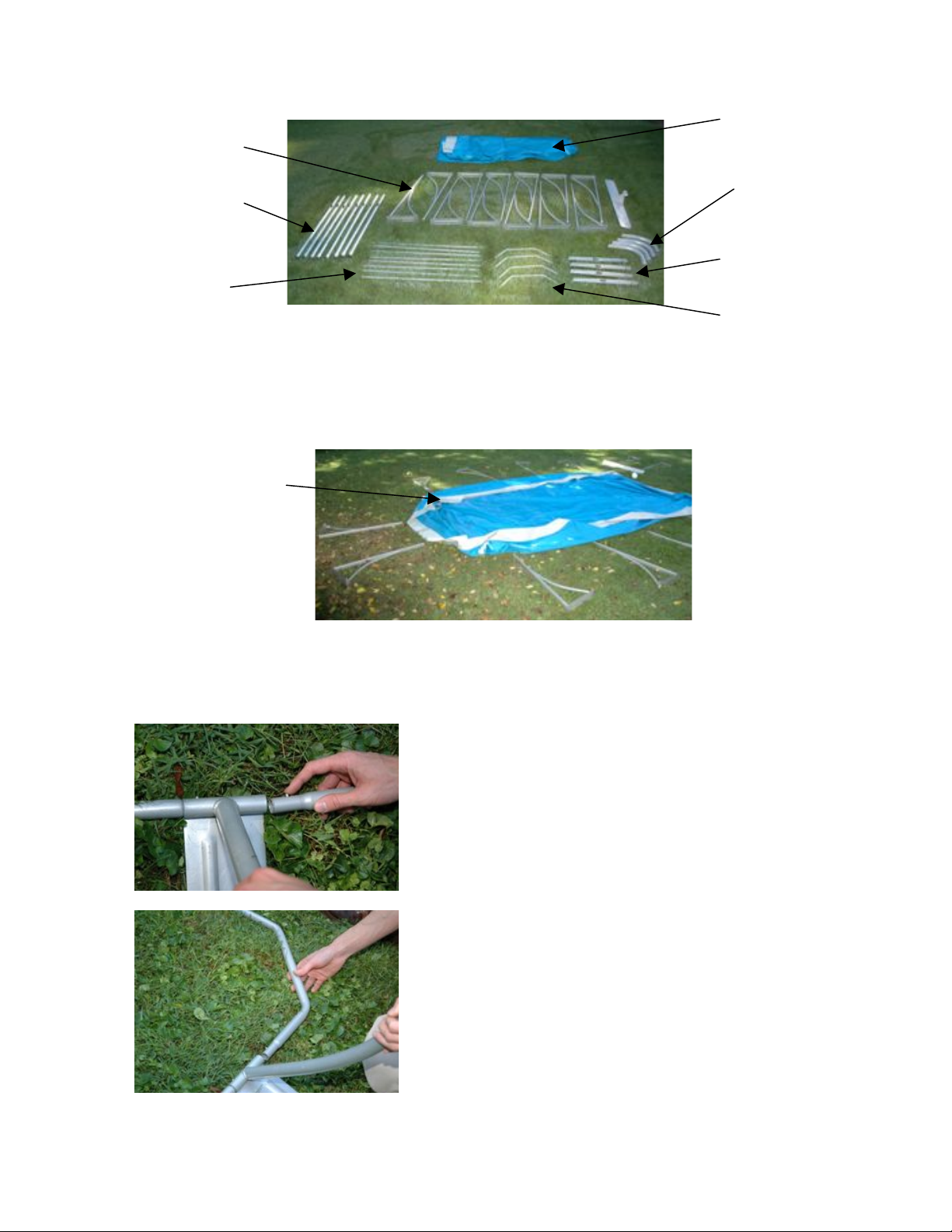
Your Fastlane Pool is shipped by common carrier and contains the following 13 packages:
1. (8) Top 130 cm Straight Tubes, wider (Part B for the pool assembly)
2. Electric Heater (optional), Skimmer, Owner’s Manual and Plumbing & Start-Up Kit
3. (1) 8’ x 16’ Solar Cover
4. (4) Top 60 cm Straight Tubes, wider (Part C for pool assembly) and (8) Straight
Bottom Tubes, thinner (Part F for pool assembly)
5. (6) Vertical Struts (Part G for pool assembly) and (4) Top Corner Tubes, wider (Part
D of pool assembly)
6. (6) Vertical Struts (Part G for pool assembly) and (4) Bottom Corner Tubes, thinner
(Part E of pool assembly)
7. (1) Ready-to-Assemble Pool Ladder
8. (1) Reinforced Fabric-Wall Pool Liner (Part A for pool assembly), (1) vinyl bag with
pins and patches, Pump 2-Speed 110-volt Processed, Filter Cartridge Housing and
Pump Base with Inserts
9. (1) Flex Tube 50’ x 1.5” sched 40
10.(1) 5 Gallon Bucket of Hydraulic Fluid
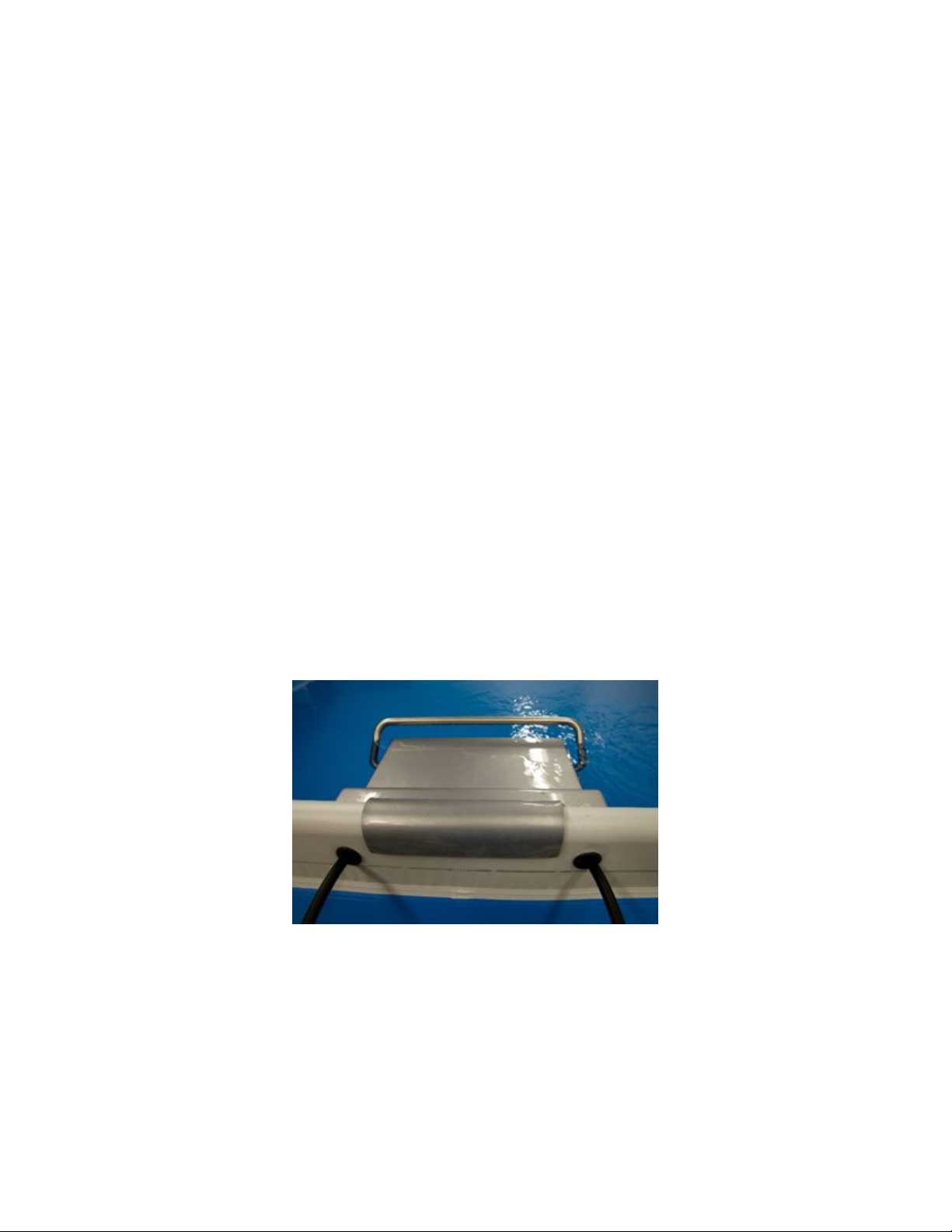
11.(1) Fastlane Swim Unit Housing
12.(1) Fastlane Swim Unit Base with attached 25’ of Hydraulic Hoses
13.(1) Fastlane Hydraulic Power Unit (5 hp standard, 6 hp optional)
14. (1) Accessory Kit, which includes:
a. (1) Hanging Bracket
b. (1) Top Bumper Piece
c. (1) Extension Bumper
d. (1) Top (of the housing)
e. (4) Liner Grommets
f. (2) Hat Sections
g. (1) Owner’s Manual Kit, which includes:
!(1) Fastlane Pool Owner’s Manual
!(34) 10-32, 3/4” Screws, 316L Stainless Steel, M/S, Phillips Truss
!(6) 10-32, 1/2” Screws, 316L Stainless Steel, M/S, Phillips Truss
!(6) 10-32 Lock Nuts, Stainless Steel
!(2) Adapters, 8 JIC Female x 6 JIC Male, 8-6TRTXN-S
POOL POSITIONING
To ensure maximum enjoyment and efficiency, consider the following steps when selecting
the desired location of your Fastlane Pool.
"Select a location that receives maximum sunlight for increased heat and extended
use.
"Select a location with as little wind exposure as possible to minimize heat loss.
"Be aware of the amount of trees and shrubbery around your pool to limit the amount
of debris.
"Select a location with accessibility to water and electric sources.
"Consider privacy when selecting a location.

P5/8/08 Page 3 of 26
GROUND PREPARATION
The surface the Fastlane Pool is to be assembled on must be firm and level. The Fastlane
Pool must be installed as level as possible, within 2”- 3” of level (from the highest point to
the lowest point of the pool). If you are going to be 2”– 3” off level, be sure to install the
skimmer on the lower side to ensure your skimmer will not suck air into the pump. If the
ground is not level, take the earth from the high side of the surface; do not add earth to
the lower area of the surface.
Once the surface is level, clear any debris or sharp objects that may be uncomfortable to
walk on or could potentially puncture the liner. A foam flooring may be added under the
liner for additional comfort.
The supporting legs (Strut-G shown below) burden much of the weight of the Fastlane Pool
and may need additional support in “soft ground” installations, or in areas that may
experience excess ground water. A 2”x 8” x 22” piece of lumber installed under each
support leg and leveled with the ground is very effective. Make sure the entire base of
each leg (Strut G) is on the 2” x 8” lumber as any over-hang may result in bending of the
leg. A concrete slab (not a paver) of the similar dimensions may be used as well. Please
note that any support(s) added under the pool structure must be sunk so that the top of
the support is level with the ground surface. Lifting the struts or frame in any manner may
cause excessive stress on the liner and frame, and may void the Fastlane Pool warranty.
(Refer to Diagram #1: Supporting Legs.)
DIAGRAM #1: SUPPORTING LEGS
POOL ASSEMBLY
Your pool is comprised of various parts. Therefore, before proceeding with installation,
ensure that all necessary parts are present and group like parts together.
Part Description Quantity
(A) Liner 1
(B) Top 130 cm straight tubes (wider) 8
(C) Top 60 cm straight tubes (wider) 4
(D) Top corner tubes (wider) 4
(E) Bottom corner tubes (thinner) 4
(F) Straight bottom tubes (thinner) 8

P5/8/08 Page 4 of 26
(G) Struts 12
1. Unfold and spread out liner (A) on the prepared area. Keep in mind your “swim
direction” when positioning the liner. When the Fastlane Pool is fully assembled, you
will be swimming towards the skimmer, so plan accordingly
2. Align the struts (G) with the prepared cut outs at top of liner.
3. Connect bottom tubes (F) to struts (G) one at a time to make the four (4) sides of
your pool. Connect corner tubes (E) to open end of both struts (G) to finish each of
the four (4) corners.
A
B
C
D
E
F
G
Skimmer Pocket

P5/8/08 Page 5 of 26
4. Connect the (B) and the (C) tubes together. NOTE: The (C) tube (shorter, wider
tube) is always the last tube on the right when facing the pool wall. (Refer
to Diagram #2: Wider Straight Tube Layout)
DIAGRAM #2: WIDER STRAIGHT TUBE LAYOUT
5. Feed the connected tubes into the corresponding sleeves of the liner. Remember to
align the top rail slots with the matching cutouts in the liner. Align slots in the top
rail with corresponding struts (G) and insert.
C
B
D

P5/8/08 Page 6 of 26
6. Insert and connect the top corner tubes (D). It may be helpful to insert both ends of
corner tube (D) into the corresponding liner sleeves, followed by pulling back and
connecting one side at a time to top rail.
7. Ensure all tubes completely nested in one another, connected correctly and that the
struts are perfectly aligned.
8. Slowly begin to fill the pool with water until the bottom of the liner is taught.
Remove any wrinkles in the pool liner as this time as it will be difficult to do once the
pool is full.
9. To prevent leaking issues, it is very important to plumb and plug both through walls
before the water level reaches the two pre-cut holes in the liner. For more
information, refer to the section in this Owners’ Manual titled, WATER QUALITY
SYSTEM, SKIMMER & THRU-WALL FITTINGS (starting on Page11).
10.Once these holes have been plugged, assemble the Fastlane Swim Unit.

P5/8/08 Page 7 of 26
FASTLANE SWIM UNIT ASSEMBLY
1. Verify that all items have arrived. NOTE: If using a power drill, do NOT over
tighten the screws, as this will strip the thread in the PVC of the Fastlane
Swim Unit.
2. Carefully unpack the Swim Unit Housing, Swim Unit Base and its components from
boxes 11, 12 and 14 as noted above. Remove and verify all hardware kits from
inside. Close the boxes and flip them upside down on the ground to use as a
workbench or collapse the boxes and use as a smooth surface to protect the
components from scratching.
3. Turn the Swim Unit Housing upside down on the box or another smooth surface.
Remove the block of wood by removing the screws that attach the wood to the Swim
Unit Housing. The wood is for packaging purposes only and may be discarded.
4. Remove the screws on the two sides and the front of the Swim Unit Housing that
secure the throat. Set the throat and the screws aside to be used in Step 13.
5. Set the Swim Unit Base on the cardboard box with the cylinder facing up. Lay the
hydraulic hoses that come pre-attached to the Swim Unit Base to each side so that
they are out of the way. Flip the Swim Unit Housing over and set on top of the Swim
Unit Base. Secure the Swim Unit Base to the Swim Unit Housing by using six (6) of
the 3/4” stainless steel screws provided (three screws on each side. NOTE: Do not
over-tighten.
6. Carefully feed the bond wire that is attached to the Swim Unit Base up through the
horizontal honeycomb grill located in the bottom of the Swim Unit Housing and up
through the turning vanes. Install the grab rail using six (6) 3/4” stainless steel
screws and the six (6) 10-32 stainless steel lock nuts provided. Secure the bond
wire that has been fed up through the turning vanes under one of the six screws.
Secure the other bond wire that has been pre-installed in the Swim Unit Housing
under a 2nd screw in the grab rail. NOTE: Do not over-tighten.

P5/8/08 Page 8 of 26
7. Run the hydraulic hose up the back of the Swim Unit Housing so that the PVC hat
channel will cover the hose. Firmly secure, but do NOT over tighten, the eight
(8) stainless screws per hat channel. Repeat for the second hose.
8. Once both hat channels are attached, pull the two hydraulic hoses tight and secure
them to the top of the Swim Unit Housing using the green hose clamps provided. To
accomplish this, unscrew the green hose clamps, insert the hoses, and re-screw
snugly into the top of the Swim Unit Housing. Locate the bonding wire attached to
the grab rail and run back along one of the hydraulic hoses.
9. Attach the acrylic hanging bracket to the back of the Swim Unit Housing with four (4)
of the eight (8) stainless steel screws provided. NOTE: Do not over-tighten.
Leave the two top screw holes unused.

P5/8/08 Page 9 of 26
10.Attach the top bumper piece (length of PVC pipe) to the Swim Unit Housing through
the unused screw holes (top holes from Step 9) in the acrylic hanging bracket using
two (2) of the eight (8) stainless steel screws provided in Step 9. NOTE: Do not
over-tighten.
11.Attach the lower extension bumper (length of PVC pipe) to the rear of the Swim Unit
Base using the two (2) of the eight (8) stainless steel screws remaining from Step 9.
NOTE: Do not over-tighten.
12.Attach the wheels to the Swim Unit base. Slide the axle through the two holes that
are marked in yellow on the intake grill in the Swim Unit base. These holes have
been widened to allow the axle to pass through freely. There is a total of four (4)
large and two (2) small washers used in the wheel assembly. Be sure that two large
washers are located between each wheel and the intake grill on the back bottom of
the Swim Unit base. Secure the wheels to the axle with one smaller washer between
the screw and the wheel on each side.
13.Re-install the throat that was removed previously in Step 4.
14.Place the Swim Unit on the ground and roll it close to the Fastlane Pool location for
installation. Be careful not to tip over the Swim Unit, as it is front-heavy.
15.Once the pool is nearly full and the pool liner is taught and wrinkle-free, carefully lift
the assembled Fastlane Swim Unit into the pool at the skimmer end. Lower and
position the Swim Unit so that the acrylic hanger is resting on the wider top 130 cm
straight tube (B) as shown in the photo on the following page. It should be centered
between the two end struts (G).

P5/8/08 Page 10 of 26
16.The hydraulic hoses can be simply left hanging over the top of the pool wall and run
back to the Power Unit. Tie the bonding wire to one of the end struts (G) located
near the Fastlane Swim Unit to bond the Swim Unit to the pool. If you choose not to
feed the hoses through the pool liner as outlined in Steps 17 & 18 below, please skip
to Step 19.
(NOTE: Steps 17 & 18 below are optional)
17. If a more finished look is desired, four rubber grommets have been provided to fit
into holes that you can cut into the top white section of the liner. Once the Fastlane
Swim Unit is placed properly in the pool centered between the end struts (G), on the
outside of the pool liner, measure 1-1/2” from one side of the acrylic hanger and 3”
down from the top of the pool. Make a dot with a permanent marker on the outside
of the liner. Place a rubber grommet over the mark so that the mark is in the center
of the grommet. Trace the INSIDE of the grommet onto the liner. Using a sharp-
blade utility knife, slowly and carefully cut out the traced circle. NOTE: Cutting a
small circle with a utility knife can be difficult. It may be best to work in
many small straight cuts for accuracy.
18.Push the grommet into the cut hole so that the fabric is inside the grooves of the
grommet. Repeat this process inside the pool as well as the other side of the
Fastlane. NOTE: The hydraulic hoses and bonding wire will be passing
through two (2) layers of fabric. It is important to feed the hydraulic hoses
and bonding wire through both grommets, starting from inside the pool and
then feeding them through the outer layer of fabric as shown in the photo
below.
19.Install the top cover of the Swim Unit Housing using six (6) 3/4” stainless steel
screws (three screws on each side).
20.Run the hydraulic hoses back to the Power Unit and tie the bonding wire to one of
the end struts (G) located near the Fastlane Swim Unit to bond the Swim Unit to the
pool.

P5/8/08 Page 11 of 26
ELECTRICAL REQUIREMENTS
Consider the electrical requirements for your particular installation before
locating the Water Quality System and gluing the plumbing parts. Different
option packages require different plumbing and electrical configurations.
Standard Fastlane Pool package with no heater
The Hydraulic Power Unit (HPU) is shipped with two whips coming from the EP1 Controller
mounted on the HPU. One whip is to be wired by an electrician from the power source into
the LINE side of the contactor and is intended to supply power to the unit. The other whip
is connected to the LOAD side of the contactor and is to be hard wired into the 220-volt,
two-speed pump with the switch on the rear of the pump by the electrician. This pump is
intended to run continuously on low speed, but can be manually switched to high speed for
cleaning. The two-speed pump will run only when the Fastlane is not in use.
Fastlane Pool Package with optional 5.5 kW Electric Heater
The Hydraulic Power Unit (HPU) is shipped with two whips coming from the EP1 Controller
mounted on the HPU. One whip is to be wired by an electrician from the power source into
the LINE side of the contactor and is intended to supply power to the unit. The other whip
is connected to the LOAD side of the contactor and is to be hard wired into the 5.5 kW
Electric Heater by the electrician. Separately, a 110-volt, two-speed pump, with the switch
on the rear of the pump and power cord with plug already wired into it done by Endless
Pools, will be supplied. This pump will plug directly into a 110-volt GFI protected outlet and
will run continuously on low speed, but can be manually switched to high speed for
cleaning. Although the pump will be running continuously, the heater will run only when
the Fastlane is not in use.
Fastlane Pool Package with optional 55,000 BTU Gas or Propane Heaters
The Hydraulic Power Unit (HPU) is shipped with two whips coming from the EP1 Controller
mounted on the HPU. One whip is to be wired by an electrician from the power source into
the LINE side of the contactor and is intended to supply power to the unit. The other whip
is connected to the LOAD side of the contactor and is to be hard wired into a junction box
that is mounted on the black equipment mounting board. Connecting to this junction box
will be two whips. One is to be hard wired into the 220-volt, two-speed pump with the
switch on the rear of the pump by the electrician. The other, also done by an electrician, is
to be hard wired into either the Gas or Propane heater in order to provide enough
electricity for the ignition switch. The pump is intended to run continuously on low speed,
but can be switched to high speed manually for cleaning. The pump and the heater will be
able to run only when the Fastlane is not in use.

P5/8/08 Page 12 of 26
WATER QUALITY SYSTEM, SKIMMER & THRU-WALL FITTINGS
A. Plumbing Kit
"PVC Primer
"PVC Glue
"Teflon Tape
"Teflon Putty
"(4) Short Lengths of Rigid PVC Pipe
"(1) 50’ Roll of Flex PVC Pipe
"Quick Disconnect (included in pump box)
B. Box of Plumbing Parts
"(9) 90-degree elbow female slip x female slip
"(2) 90-degree street elbow male thread x female slip
"(2) Thru-wall fitting female thread inside x female slip outside
"(4) Union female slip x female slip
"(2) Union female thread x female slip
"(1) Tee, reducing, threaded
"(1) Hose valve
"(3) Ball valve female slip x female slip
"(2) Adapter male thread x male slip
"(13) Nipple
"(1) Eyeball fitting male thread
"(2) Plug threaded
C. Additional Tools Required
"Tape measure
"Hack saw
Fittings and Piping
Endless Pools, Inc. has provided a sufficient quantity of PVC fittings and piping for most
installations. There are extra fittings provided. Additional fittings and pipe can be
purchased locally at most hardware stores. Be sure to use “pressure” fittings rather than
standard drain fittings. A “pressure” fitting provides for a stronger bond between fitting
and pipe due to a larger gluing surface. All fittings and pipe should be Schedule 40 1-1/2”
PVC.
Box of Plumbing Parts
Please refer to Sections A and B of the Water Quality System for quantities shipped.

P5/8/08 Page 13 of 26
NOTE: Pictures are not drawn to scale. Parts can be ordered from
Endless Pools, Inc., a local hardware store or a plumbing supply store.
QTY = 1
QTY = 1
QTY =9
QTY = 2
QTY = 2
QTY = 4
QTY = 2
QTY = 13
QTY = 3
QTY = 2
QTY = 1
QTY = 2

P5/8/08 Page 14 of 26
SKIMMER ASSEMBLY
1. Slip the skimmer gasket onto each side of the supporting pocket, making sure to
align the holes with each other.
2. Put the skimmer into the pocket with the throat against the gasket.
3. Align and place the faceplate on the outside of the gasket and affix by using the
provided screws.
4. Snap in weir door, add basket and push the lid into place. Only use the included
skimmer plate if using a Vacuum or Suction Cleaning system.
CONNECTING SKIMMER WALL FITTING
(Refer to Diagram #3: Rectangle Skimmer Diagram on the following page)
"Push fitting (#8) thru the wall of the pool from the inside. MAKE SURE TO USE A
GASKET (#9) on both sides of the wall of the pool. Place cork ring next to the
gasket outside the pool and secure the wall-fitting nut (#10) to (#8) now sticking
out of the wall of the Fastlane Pool. Tighten with a large pair of channel locks. Make
sure the nut is very snug but do not over-tighten, as this may crack your fitting.
"Thread the male portion on the male adaptor (#3) into the bottom of the skimmer.
NOTE: No glue or tape is necessary to complete this step.
"Inside the pool, thread the male portion of the threaded 90 (#5) into the thru-wall
fitting (#8). NOTE: No glue or tape is necessary to complete this step.
"Press the connection pipe (#4) into the male adapter (#3), then press the other end
of the pipe into the female end of the threaded 90 (#5). NOTE: You may have to
lift slightly on skimmer to make this connection.
"Outside the pool, glue the male portion of the street ell (#6) into the tailpiece of the
thru-wall fitting (#8).
"The provided plugs can also be threaded into the threaded end of the thru-wall fitting
to prevent the pool from draining when the water quality system equipment needs
maintenance.
DIAGRAM #3: RECTANGLE SKIMMER DIAGRAM
Thru-Wall

P5/8/08 Page 15 of 26
CONNECTING RETURN WALL FITTING
(Refer to Diagram #4: Wall Fitting Diagram)
•Push fitting (#8) thru the wall of the pool from the inside. MAKE SURE TO USE A
GASKET (#9) on both sides of the wall of the pool. Place cork ring next to the gasket
outside the pool and secure the wall-fitting nut (#10) to (#8) now sticking out of the
wall of the Fastlane Pool. Tighten with a large pair of channel locks. Make sure the nut
is very snug but do not over-tighten, as this may crack your fitting.
•Outside the pool, glue the male portion of the street ell (#6) into the tailpiece of the
thru-wall fitting (#8).
•Thread the eyeball fitting into the threaded end of the thru-wall fitting (#8). Point the
eyeball towards the bottom of the pool for optimal water circulation in the Fastlane Pool.
•The provided plugs can also be threaded into the threaded end of the thru-wall fitting to
prevent the pool from draining when the water quality system equipment needs
maintenance.
DIAGRAM #4: WALL FITTING DIAGRAM
Drainage
Drainage needs to be provided around the pool and near the water quality equipment. It is
important to be prepared in the unlikely event of a leak. It is ideal to install floor drains in
the area just outside the pool (if indoors), but not directly under the pool itself. It is worth
the time and effort now to install a drainage system rather than be unprepared in the event
of a mishap.
Pump/Filter Connector
The pump/filter connector has been pre-plumbed at the factory. It is located in the
circulating pump box. When installing this piece, be sure to verify that the rings have been
seated properly and that you have applied Teflon to the threads of the black adapter piece
that goes into the pump.
Thru-Wall

P5/8/08 Page 16 of 26
The Equipment
Please refer to the drawings and photographs on the following pages for suggested
plumbing layouts. While it is important to follow the general layout, the equipment can be
laid out to suit the specific needs of your site. Please call your Endless Pool design
professional if you need guidance on equipment location. Be sure to install the ball valves,
hose bibb and unions in the order we have shown. Their location is important for the
maintenance requirements of the system. In addition, do not locate the equipment more
than one foot above or five foot below the water level. If this condition is present at your
site, please call our Customer Service Department at 1-800-910-2714 to discuss
installation.
Standard Water Quality System
Standard Water Quality System Plumbing

P5/8/08 Page 17 of 26
Optional Gas Heater/Water Quality System
Optional Gas Heater/ Water Quality System Plumbing
Mounting and Equipment
Mount the equipment to the PVC board using the hardware supplied with the circulating
pump. The two (2) 3/8” bolts are used to fasten the circulating pump using the threaded
inserts already located in the base. Use the self-drilling fasteners to mount the filter tank
and electric heater to the PVC board. A gas heater should not be mounted to the PVC
board. Once again, please refer to the drawings and photographs above for suggested
plumbing layouts.

P5/8/08 Page 18 of 26
Equipment Plan and Elevation
The standard water quality system with electric heater requires about 4’ x 5’ of
floor/ground space. The water quality equipment can be arranged horizontally or vertically
to fit specific spaces. 36” minimum vertical clearance is required to remove the filter
cartridge. As mentioned previously, suitable drainage must be provided at both the
Fastlane Pool and the water quality system. All electric components must be located,
installed and bonded by a licensed local electrician in accordance with applicable codes.
WARNING: ALL CIRCUITS MUST BE GFI PROTECTED.

P5/8/08 Page 19 of 26
FASTLANE POWER UNIT ASSEMBLY
Placement Considerations
The Power Unit should be elevated from the ground and placed on a flat surface. If placing
the Power Unit outside, it is recommended the Outdoor Power Unit with Weather Guard be
purchased to protect it against the everyday elements. If placing the unit indoors at a level
below the pool deck, such as a basement, a floor drain is mandatory to accommodate the
unlikely event of a hole developing in one of the hydraulic run hoses creating a siphon.
Whether placing indoors or outside, this is an air-cooled unit and must have ample
ventilation. Therefore, a minimum of 12” of air space must be provided on all sides of the
Power Unit motor. In addition, the Power Unit needs to be checked periodically for
maintenance and should be easily accessible.
1. Carefully remove the Power Unit from the packaging. NOTE: The Power Unit is
heavy.
2. Place the Power Unit in the selected position and verify that the hose connections are
pointed in the direction you desire.
3. Connect the hydraulic hoses that either hang over the pool wall or go through the
pool liner to the Power Unit. NOTE: The low-pressure hose has red tape on the
end. Connect the low-pressure line to the post at the fill cap and the high-pressure
line to the port with the proportional relief valve.
4. Have an electrician make the electrical connections using the whip provided. Make
this connection by hard wiring to a disconnect or using an appropriate lock tight plug
and socket. The Power Unit requires a single-phase 220-volt, 30 amp GFCI
protected power. (Refer to Diagram #5: Power Unit Electrical Wiring.)

P5/8/08 Page 20 of 26
5. Turn the circuit breaker to the Power Unit OFF. Fill the Power Unit with the 5 gallons
of hydraulic fluid provided. NOTE: The fill cap is at the low-pressure fitting.
6. Remove the oil filter by lifting it out of the fill opening. Once filled with oil, replace
the oil filter and cap and press firmly to ensure proper seating of the filter.
7. If your hydraulic hose is a sufficient length to require additional fluid, it will be
included with the hydraulic run hose. In this case, fill with the full five gallons first
and run the Power Unit for one minute to fill the hydraulic run hoses. Turn Power
Unit off and add the additional oil. NOTE: Do not run the Power Unit without
the fill cap in place.
8. Be sure to bond the Fastlane Pool and the hydraulic Power Unit by connecting a #8
or larger copper bonding wire to the bonding lug located ?????? and running that
wire (typically along with the hydraulic hoses) back to the hydraulic Power Unit. Any
other piece of pool equipment with a bonding lug should also be bonded to the same
loop as the Fastlane Pool and the hydraulic Power Unit.
DIAGRAM #5: POWER UNIT ELECTRICAL WIRING
Table of contents
Other Endless Pools Swimming Pool manuals

Endless Pools
Endless Pools FASTLANE SPORT User manual

Endless Pools
Endless Pools 2001779 User manual

Endless Pools
Endless Pools FastLane Assembly instructions

Endless Pools
Endless Pools Swim Spa User manual

Endless Pools
Endless Pools Streamline User manual

Endless Pools
Endless Pools RECSPORT R200 User manual

Endless Pools
Endless Pools FASTLANE PRO User manual

Endless Pools
Endless Pools X2000 SwimCross User manual

Endless Pools
Endless Pools Winterizing Pool Series Original operating manual

Endless Pools
Endless Pools Pools User manual