manuals.online logo
Brands
  1. Home
  2. •
  3. Brands
  4. •
  5. Groth
  6. •
  7. Tank Equipment
  8. •
  9. Groth 2000A Instruction manual

Groth 2000A Instruction manual

This manual suits for next models

3

Other Groth Tank Equipment manuals

Groth 7658A Installation and operating instructions

Groth

Groth 7658A Installation and operating instructions

Popular Tank Equipment manuals by other brands

ARKSEN 002-AU-30035/GAS35 owner's manual

ARKSEN

ARKSEN 002-AU-30035/GAS35 owner's manual

Gardena 4000/5 eco operating instructions

Gardena

Gardena 4000/5 eco operating instructions

morse 185G Operator's manual

morse

morse 185G Operator's manual

TransTank FloodRite Operator's handbook

TransTank

TransTank FloodRite Operator's handbook

KABI TruckTank TT250 operating manual

KABI

KABI TruckTank TT250 operating manual

Kessel 28015 installation manual

Kessel

Kessel 28015 installation manual

Astro Pneumatic Tool PT2-4 quick start guide

Astro Pneumatic Tool

Astro Pneumatic Tool PT2-4 quick start guide

Franklin Fueling Systems EVO 600 Operation guide

Franklin Fueling Systems

Franklin Fueling Systems EVO 600 Operation guide

TransTank TopCrop Operator's handbook

TransTank

TransTank TopCrop Operator's handbook

WELBA TW-32 quick start

WELBA

WELBA TW-32 quick start

Amtrol FILL-TROL FT-109 Installation & operation instructions

Amtrol

Amtrol FILL-TROL FT-109 Installation & operation instructions

Regulus RBC 200 Installation and operation manual

Regulus

Regulus RBC 200 Installation and operation manual

Cordivari Bolly1 PDC user manual

Cordivari

Cordivari Bolly1 PDC user manual

Nahita ZFD013 manual

Nahita

Nahita ZFD013 manual

IVT LATENTO XXL Series Mounting instruction

IVT

IVT LATENTO XXL Series Mounting instruction

Wilo VBH Series Installation and operating instructions

Wilo

Wilo VBH Series Installation and operating instructions

Endress+Hauser silometer FMC 671 Z Operating	 instruction

Endress+Hauser

Endress+Hauser silometer FMC 671 Z Operating instruction

Western Global FUELCUBE R2 product manual

Western Global

Western Global FUELCUBE R2 product manual

manuals.online logo
manuals.online logoBrands
  • About & Mission
  • Contact us
  • Privacy Policy
  • Terms and Conditions

Copyright 2025 Manuals.Online. All Rights Reserved.

IOM2000A.4
Rev. A 12541
© 2008 Groth Corporation
Installation, Operation and Maintenance Manual for
Emergency Relief Valve
Models 2000A, 2050A, 2400A, 2450A
2
TABLE OF CONTENTS:
INTRODUCTION: 2
DESIGN, FUNCTION & OPERATION 3
GENERAL SAFETY INSTRUCTIONS 4
SAFETY WARNINGS 4
INSPECTION AND INSTALLATION 5
PREVENTIVE MAINTENANCE 6
MODEL 2000A DISASSEMBLY & ASSEMBLY 7
MODEL 2050A DISASSEMBLY & ASSEMBLY 8
MODEL 2400A DISASSEMBLY & ASSEMBLY 12
MODEL 2450A DISASSEMBLY & ASSEMBLY 13
TESTING AND SETTING PROCEDURE 17
MODEL INFORMATION 13
PRODUCT LIMITED WARRANTY 13
INTRODUCTION:
Groth’s Emergency Relief Valve (ERV) is designed to provide emergency relief capacity beyond that furnished by
the normal operating pressure relief valve on the tank. They are used on liquid storage tanks and other process
vessels or systems to prevent structural damage due to excess internal pressure or vacuum that could result under
emergency situations due to fire exposure or failure of the inert gas blanketing system.
Storage tanks are pressurized when liquid is pumped in, compressing the existing vapor or when increasing
temperature causes increased evaporation or expansion of existing vapor. Conversely, vacuum may be created
when pumping out or due to decreasing temperature. To prevent damage, vapor must be allowed to escape or enter
the tank at a specified pressure or vacuum condition. The volume rate of venting depends upon the tank size,
volatility of the contents, the pumping rate and the temperature. See API Standard 2000 for the procedures to
determine venting requirements.
The valves are designed to be self closing under normal operation. As excessive pressure builds up, the valve
relieves and then reseats when over pressure has been dissipated. Some models have a restraining cable to
connect the head and flanges and also serve as a grounding cable.
The pallets include Groth's special "cushioned air" seating. FEP seating diaphragms are standard; they minimize
sticking caused by resinous vapors and atmospheric moisture. Diaphragms are also available in Buna-N, FKM and
other elastomers. Peripheral guides insure proper alignment and integrity of the seating.
The ERVs are preset at the factory in accordance with the purchase order's instructions. These settings are printed
on the stainless steel name tag.
The valve must be maintained by a knowledgeable valve technician. It should only be assembled under clean
conditions preferably in a shop environment. Carefully read and understand this Manual before installing or repairing
this valve.
For information not contained in this manual, please contact:
Groth Corporation
13650 N. Promenade Blvd
Stafford, TX 77477
281-295-6800 (Phone)
281-295-6995 (Fax)
3
DESIGN, FUNCTION & OPERATION
The 2000A Series was designed as a cost effective valve that would protect a tank by providing
emergency pressure relief caused by fire or other factors that could make the pressure rise.
Groth manufactures four models in this series [Table 1] for pressure relief; two models also
provide vacuum relief.
Table 1 : Model Identification
Model Pressure Vacuum Description
2000A Y Guided Cover
2050A Y Y Guided Cover w/ vacuum relief
2400A Y Hinged Cover
2450A Y Y Hinged Cover w/ vacuum relief
Model 2000A provides pressure relief only; vacuum relief must be supplied by a separate
breather valve. Model 2050A provides pressure relief and vacuum relief through a spring
loaded port integral to the cover assembly. A weatherhood and screen are provided for
protection.
Model 2400A incorporates a hinged pivot point for the cover, providing additional alignment for
the cover so it reseats properly after venting. The Model 2450A adds vacuum relief capability
while keeping the hinge design. The hinged design closes after relieving pressure or vacuum.
All valve covers can be lifted off the base, providing quick access for tank inspection and
maintenance. Note: Depending on pressure setting, it may be necessary to use a crane or
other lifting device to open or remove the cover assembly. A typical tank installation is shown in
Figure 1 which includes a Pilot Operated Pressure/Vacuum Relief Valve, a Gas Blanketing
Regulator and the 2000A Emergency Relief Valve which provides emergency pressure relief.
Groth Corporation manufactures all of these devices.
Figure 1: Tank Installation - Safety Equipment
4
GENERAL SAFETY INSTRUCTIONS
This section is an overview of safety guidelines that should be followed during the installation, operation and
maintenance of Groth Pressure / Vacuum Relief Valves. To understand the context of these instructions and
warnings, it is necessary to completely read and understand the contents of this manual.
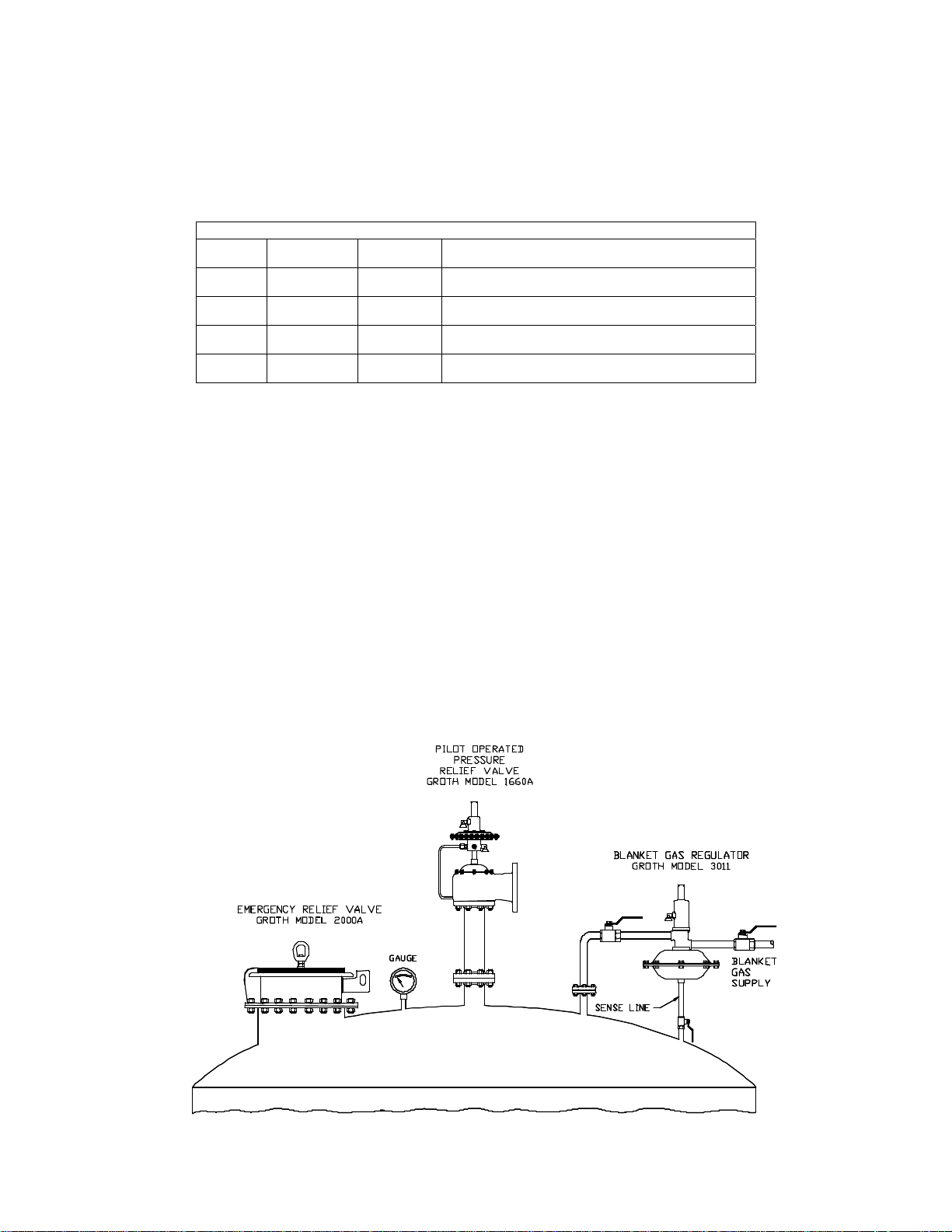
The purpose of a pressure/vacuum relief valve is to prevent excessive pressure or vacuum in a tank or process
system. The valve must be designed for the proper MAWP and flow requirements of the system. Consult API
Standard 2000 for tank protection sizing procedures. An improperly specified or functioning relief valve may result in
structural damage to the tank or system, and can cause severe personal injury or death.
SAFETY WARNINGS
THE PURPOSE OF AN EMERGENCY RELIEF VALVE (ERV) IS TO PREVENT EXCESSIVE PRESSURE IN A
TANK OR PROCESS SYSTEM UNDER EMERGENCY SITUATIONS. THE VALVE MUST BE DESIGNED FOR
THE PROPER MAWP AND FLOW REQUIREMENTS OF THE SYSTEM. CONSULT API STANDARD 2000 FOR
TANK PROTECTION SIZING PROCEDURES. AN IMPROPERLY SPECIFIED OR FUNCTIONING EMERGENCY
RELIEF VALVE MAY RESULT IN STRUCTURAL DAMAGE TO THE TANK OR SYSTEM AND SEVERE
PERSONAL INJURY OR DEATH.
THE ERV SET PRESSURE AND SET VACUUM ARE SET AT THE FACTORY PER PURCHASE ORDER
SPECIFICATIONS. THE SET PRESSURE AND NOMINAL FLOW CAPACITY ARE STAMPED ON THE VALVE
NAMEPLATE. DO NOT ATTEMPT TO READJUST THE SET PRESSURE. DO NOT CHANGE PRESSURE
RATING BY ADDING ADDITIONAL WEIGHTS TO THE PALLET ASSEMBLY WITHOUT CONSULTING
FACTORY. ADDING MORE WEIGHTS THAN RECOMMENDED WILL RESULT IN AN INCREASE IN SETTING.
DO NOT ATTEMPT TO LIFT PALLET ASSEMBLIES BY HAND. THESE ASSEMBLIES CAN WEIGHT IN EXCESS
OF 400 LBS. AND COULD CAUSE BODILY INJURY WITHOUT THE USE OF AN EXTERNAL LIFTING METHOD.
MODEL 2000A AND 2050A VALVES WILL LIKELY NOT RESEAT AFTER A SIGNIFICANT OVER-PRESSURE
CONDITION. IF THIS IS NOT ACCEPTABLE, IT IS RECOMMENDED TO USE EITHER MODEL 2400A OR 2450A.
EMERGENCY RELIEF VALVES ARE DESIGNED TO PROVIDE FULL RATED CAPACITY AT 100% OVER-
PRESSURE. IF THE VALVE IS TO BE OPERATED AT A REDUCED OVER-PRESSURE, CONSULT FACTORY
FOR ACTUAL FLOW CAPACITY UNDER SPECIFIED CONDITIONS.
DO NOT MIX PALLET ASSEMBLIES FROM DIFFERENT VALVES. FAILURES TO ENSURE THAT THE PALLET
ASSEMBLIES ARE INSTALLED IN THE ORIGINAL AND CORRECT LOCATION CAN CHANGE THE PRESSURE
OR VACUUM RELIEF SETTINGS. THIS CAN CAUSE A TANK FAILURE.
DO NOT LOOSEN HEX NUTS UNTIL ALL SPRING COMPRESSION HAS BEEN RELEASED. SPRING PRE-
LOAD IS SUBSTANTIAL AND COULD CAUSE SEVERE PERSONAL INJURY IF FASTENERS WERE REMOVED
WITH THE SPRING COMPRESSED.
DO NOT ATTEMPT TO REMOVE THE VALVE FROM THE TANK OR PROCESS VESSEL WITHOUT FIRST
BLEEDING ALL PRESSURE FROM THE SYSTEM. ALTERNATIVE MEANS OF PRESSURE RELIEF MUST BE
PROVIDED WHEN THE VALVE IS OUT OF SERVICE.
THE VALVE HAS BEEN EXPOSED TO PROCESS VAPORS WHILE IN SERVICE. OBSERVE ALL PLANT
PROCEDURES AND MATERIAL SAFETY DATA SHEETS (MSDS) FOR THE PRODUCTS IN THE SYSTEM
WHEN INSPECTING, ADJUSTING OR SERVICING THE VALVE. TAKE APPROPRIATE SAFETY
PRECAUTIONS REGARDING EYE PROTECTION, RESPIRATION AND SKIN CONTACT.
DO NOT ADD ANY WEIGHT TO THE PALLET ASSEMBLY, CHANGE THE ADJUSTMENT SCREW (CHANGING
SET PRESSURE OR VACUUM), OR CHANGE PALLET STEM WITHOUT FIRST CONSIDERING THE
ALLOWABLE TANK PRESSURE OR WITHOUT MEASURING DESIGN LIFT TO ENSURE THE LIFT IS NOT
RESTRICTED. RESTRICTING VALVE LIFT COULD “CHOKE” THE VALVE AND NOT ALLOW FOR FULL
RATED CAPACITY. CHANGING THE WEIGHT OR ADJUSTMENT OF A SPRING COULD ALSO RESTRICT THE
LIFT OF A VALVE AT A SPECIFIED OVERPRESSURE, REDUCING THE RATED CAPACITY OF THE VALVE.
UNDER THESE CONDITIONS, THE VALVE WILL NOT PROTECT THE TANK FROM RUPTURING DUE TO
CHANGES IN INTERNAL PRESSURE. TANK FAILURE CAN CAUSE MATERIAL DAMAGE AND LOSS AND
RESULT IN SEVERE PERSONAL INJURY OR DEATH.
THE ERV IS EQUIPPED WITH A GROUND STRAP TO PREVENT STATIC ELECTRIC DISCHARGE. THIS
STRAP MUST BE SECURED TO A PROPER GROUND WHILE ALLOWING VALVE OPERATION. IF THIS
STRAP IS IMPROPERLY GROUNDED, STATIC DISCHARGE COULD CAUSE TANK RUPTURE AND RESULT IN
SEVERE INJURY OR DEATH.
5
INSPECTION AND INSTALLATION
The ERV is packed and supported to prevent damage or contamination during shipping. It should be similarly
protected during subsequent handling and storage. Before installation inspect the unit visually. If there are
indications of physical damage or internal contamination, the valve must be disassembled, cleaned and inspected
before installation.
Inspect the valve for any sign of damage that may have occurred in shipment and report this to the carrier. The seat
protector (rubber strip placed over the valve seat) shall be removed before placing the valve into service.
Handles/Eye Nuts are provided on the upper weight plates for handling the pallet assembly. The body has three
lifting eyes that are used to lift and position the body. To avoid damage to the lower flange surface, set the valve on a
soft clean gasket material until it is ready to be installed. It should be stored in a clean environment until it is to be
mounted on the tank.
The 2000A Series Emergency Relief Valve is a device that must be handled carefully to ensure seat tightness. The
body is manufactured from thin steel plate material and can be damaged by over-tightening the studs or mounting on
a tank nozzle that is not flat. The valve is also equipped with a grounding strap that should be grounded properly to
prevent static electric discharge.
The standard bodies are furnished with flat flanges; the valve should be mounted on a flat faced 150# ANSI or API
650 flange. It is recommended to use a full faced gasket to avoid deflecting the body flange. The connecting flanges
must be flat within 0.015" and clean, free of scratches, corrosion and tool marks.
All valves should be installed using the three body lifting lugs. Mount the valve with the pallet assembly in the
horizontal plane.
1. Begin by inspecting the gasket; make sure that the material is suitable for the service. Gasket dimensions are
listed in Table 2 below:
2. Lubricate all studs and nuts with an appropriate thread lubricant. If stainless steel fasteners are used, select an
anti-seize lubricant such as moly-disulfide.
3. Align the gasket with the bolt circle.
4. Set the valve body carefully on the nozzle; keep the gasket between the flanges. Install the studs and tighten
nuts hand tight.
5. Torque all fasteners to half the recommended value (see Table 3) in a staggered, alternating pattern or follow
appropriate plant maintenance guidelines and standards.
*Note: Torque values are based on a gasket factor m=3.5,
gasket factor y=2000 psi, maximum pressure = 2 psi.
6. Make sure that the flanges are not distorted and that the gasket is evenly compressed.
7. Make up the final torque and check that no further nut rotation occurs.
8. For Model 2000A and Model 2050A, the cover assembly may be independently lifted into position by using the
handles/eye nuts supplied for the weight plates. Align the pallet assembly peripheral guides with the body bore
and carefully lower the cover assembly until it seats against the body.
Table 3: Recommended Torque Values*
Size Qty
Holes
Bolt
(in)
(UNC)
Torque (ft-lbs)
Raised
Face Flange
Face
150 ANSI
16” 16 1.000 52 104
20” 20 1.125 63 110
24” 20 1.250 86 148
API650
20” 20 0.625 35 53
24” 20 0.625 43 61
T
able 2: Body Flange Gasket Dimensions
Type Flange O.D.
(in) I.D.
(in) B.C.
(in) Hole
(in) Qty.
FF 16" – 150 # 23.50 15.25 21.25 1.13 16
FF 20" – 150 # 27.50 19.25 25.00 1.25 20
FF 24" – 150 # 32.00 23.25 29.50 1.38 20
FF 20” – API
650 26.00 19.25 23.50 .75 16
FF 24” – API
650 30.00 23.25 27.50 .75 20
6
PREVENTIVE MAINTENANCE
The 2000A Series valves do not require routine lubrication or adjustments, but should be checked periodically, at least twice a
year, to confirm that the valve is functioning properly.
Because these valves provide emergency protection, they will not normally cycle in service. Inspection of seat tightness should
be done to ensure compliance with local air pollution control requirements as needed. When inspecting the diaphragms,
gaskets and seals should also be checked. Please refer to handling instructions listed in the Installation section of this manual.
Always keep records of maintenance performed.
WARNING
If the valve must be removed from the tank for any reason, make sure that all pressure has been released before the flange
fasteners are loosened. Refer to your company procedures before venting the tank pressure and when handling toxic or
otherwise hazardous materials.
The main valve body, gaskets and all other components are exposed to the process vapor. Observe all standard safety
precautions as specified on Material Safety Data Sheets for the product[s] in the system while removing the valve and when
repairing it. Take appropriate safety precautions regarding eye protection, respiration & skin contact.
The table below shows the various configurations that make up a 2000A Series valve. Identify the valve, and read the
appropriate section.
Table 4: Configurations
Models Page Guided
Cover Hinged
Cover Vacuum
Assembly
2000A 8 X
2050A 9 X X
2400A 13 X
2450A 14 X X
Each section will describe the disassembly and assembly procedures. Each section references part numbers for that valve only.
Use the diagrams preceding each section.
Inspect the soft goods, the seat, and the flanges to ensure seal tightness. Replace components as necessary.
SOFT GOODS KITS
A soft goods kit consists of the diaphragms and washers, if needed. The following system is used to identify and order kits:
Table 5: 2000 Series – Soft Good Kits Numbering System
Prefix Model No. Size Soft Good Material
KS
2000 = 2000A
2050 = 2050A
2400 = 2400A
2450 = 2450A
16 = 16”
20 = 20”
24 = 24”
A = Aflas
B = Buna-n
K = FFKM
T = Fluoropolymer
V = FKM
Note: Soft goods for the 2000 and 2000A Model Series are interchangeable.
Example:
KS200016T – A Soft goods kit for a 16"2000 valve made of Fluoropolymer.
7
MODEL 2000A DISASSEMBLY & ASSEMBLY
ITEM DESCRIPTION ITEM DESCRIPTION
1 Body 7 Hex Nut, 3/4"-10 UNC
2 Pallet 8 Washer, 3/4", PTFE
3 Retainer Plate 9 Diaphragm
4 Flat Washer, 3/4", SS 10 Hex Bolt, 3/4"-10 UNC
5 Ground Cable 11 Weight Plate(s)*
6 Sleeve 12 Eye Nut*
* Not used on valves with low settings
2000A Disassembly
1. Read “Warning” sections on page 5. Remove the valve from the tank.
2. Using the eye nut [12], or the edges of the pallet, lift vertically. Set the cover on a short length of pipe
(minimum 6” high). This will elevate the retainer plate peripheral guides above the table so they
aren’t bent or damaged.
3. Place the assembly with the ¾” hex bolt in a vise, or use a wrench to hold the center bolt from the
bottom side. Loosen the hex nuts and remove. Lift the weight plate [11], pallet [2], and diaphragms
[9].
2000A Assembly
1. Prior to final assembly, verify that the body seat area is free of corrosion, damage or product build-up.
The seat should be carefully cleaned, if necessary.
NOTE: If the seat is damaged it must be lapped using a perfectly flat ground metal disc. Wipe
seating surface clean before proceeding. Soft goods should normally be replaced whenever
valve maintenance is performed.
2. Reverse the steps of Disassembly, starting with the retainer and cover. If a diaphragm is an
elastomer, place it between the fluoropolymer diaphragm and the retainer plate. See Figure 3b.
NOTE: When replacing the ground cable, surface corrosion must be completely cleaned to allow
cable to ground pallet to tank nozzle.
3. The valve should be tested on a pressure test stand to verify the settings and evaluate seat tightness
follow instructions on page 19. Mount valve on tank; see Installation on page 6.
8
MODEL 2050A DISASSEMBLY & ASSEMBLY
ITEM DESCRIPTION ITEM DESCRIPTION
1 Body 17 Stem Guide
2 Pallet – Pressure 18 Seat – Vacuum
3 Retainer Plate – Pressure 19 Hex Bolt, 3/8"-16 UNC
4 Flat Washer, 3/8", SS 20 Flat Washer, 3/8", SS
5 Ground Cable 21 Hex Nut, 3/8"-16 UNC
6 Sleeve 22 Lock Washer, 3/8"
7 Hex Nut, 3/8"-16 UNC 23 Pallet – Vacuum
8 N/A 24 Retainer Plate – Vacuum
9 Flat Washer, 3/8", PTFE 25 Crown Nut, 3/8"-16 UNC
10 Diaphragm – Pressure 26 Screen
11 Diaphragm – Vacuum 27 Weatherhood Post
12 Spacer 28 Water Dam*
13 Weatherhood 29 Weight Plate*
14 Stem – Vacuum 30 Handle*
15 Hex Nut, 1/2"-13 UNC 31 Spring
16 Spring Button * Not used on valves with low settings.
2050A Disassembly
1. Read “Warning” sections on page 5. Remove the valve from the tank.
2. Lift pressure/vacuum pallet [2] assembly from body [1].
3. Using the handles [30] on the weight plate [29], or the edges of the pallet, lift vertically. Set the cover
on three evenly spaced support blocks (Figure 6). This will elevate the retainer plate peripheral
guides above the table so they aren’t bent or damaged.
4. Remove nuts [25], lift weatherhood [13], bird screen [26] and set aside. Remove the nut holding the
ground cable [5], and remove the cable.
5. Record “A” dimension (Figure 7). Place a short length of pipe (minimum 6” high) beneath the
vacuum pallet [23] to prevent it from falling. Back the top nut [15] completely off the stem. Compress
the spring using the spring button [16] and grasp the stem (Figure 8). Caution: Remove the second
9
nut from the stem. Slowly raise the spring
button to release the spring compression. The
spring force will be in 5 – 30 lb range, depending
on vacuum setting.
6. Using weight plate handles, if included, lift pressure
pallet [2] with attached assembly and remove
vacuum pallet-stem [23, 14] assembly from the
bottom.
7. Remove the nuts on the weatherhood posts holding
the stem guide [17]. Note: For low pressure
settings, a weight plate is added on the stem guide
[17].
8. Lift the spacers [12]. Remove the nuts above the
water dam [28]. Note: Water dam is only used if
weight plate is mounted directly on pressure pallet
[2].
9. Remove the weatherhood posts [27] by loosening
the nuts beneath the pallet.
10. Carefully lift the weight plate [29] vertically.
Caution: This may require a crane due to the
weight. (See Warning on page 5.)
11. Turn pallet assembly upside down (Figure 9).
12. Remove remaining bolts, nuts, and washers [7, 9,
19, 20, 21] to separate the vacuum seat.
13. Lift the retainer plate [3] and diaphragms [10] from
the pressure pallet.
2050A Assembly
Rebuild the valve reversing the disassembly steps.
1. Begin by placing the pallet [2] upside down on
support blocks evenly spaced or on a pipe.
2. Wipe clean “air cushion” groove (seat area) in
pallet.
3. Center diaphragms [10] (qty 2) on pallet. See
Figure 3 for orientation of diaphragms, if elastomer
is used.
4. Place retainer plate [3], align with pallet hole
pattern.
Figure 7 : Vacuum Spring Compression
Figure 8 : Loosening Nuts for Spring
Figure 6 : Pallet Support (2050A)
10
Figure 10: Sealant tape on Vacuum Seat
5. Apply PTFE sealant tape around the inside hole pattern of
the vacuum seat [18] (Figure 10). Tape should be at least
1/16” thick. Note: Other sealants (such as Silicone) can
replace the fluoropolymer tape if compatible with tank
products.
6. Position the vacuum seat [18] as shown from beneath the
pallet.
7. Align vacuum seat with pallet and insert 4 bolts (at 90
degrees from each other) from the top using fasteners
shown in Figure 9 [7, 19, 20, 21].
8. Insert four more bolts, leaving four holes, at 90 degrees from
each other, open. The weatherhood posts are installed in
these holes.
9. Turn pallet assembly right side up, and place on support blocks again.
10. Run 3/8” hex nut up 1 1/2” from end on all thread and insert weatherhood posts [27] in remaining
holes. A Fluoropolymer washer, flat washer and nut are installed from the bottom. Allow
approximately 2 threads past the nut to be free. The four weatherhood posts should all extend
approximately 11.13” above the pallet.
11. Lower the weight plate [29] (if needed for setting).
12. Use a sealant tape around the inner edge of the weight plate. Note: Other sealants (such as Silicone)
can replace the Fluoropolymer tape if compatible with tank products.
13. Insert the waterdam [28] using the weatherhood posts [27] as a guide. Use sealant tape on bottom
side, outside of its hole pattern. Tighten nuts. Note: Do not over-tighten. It is suggested to first
hand tighten the nuts, torque 15 ft-lbs in an alternating criss-cross pattern.
14. Insert the spacers [12], and the stem guide [17]. Tighten nut to retain to pallet assembly.
15. If pallet assembly is high enough from the table, insert vacuum pallet-stem [23, 24, 14] assembly
from beneath. Place a short length of pipe (minimum 6” high) beneath the vacuum assembly to hold
it in place until the spring is installed.
Figure 9: Exploded View of Pallet Assembly (Upside Down)