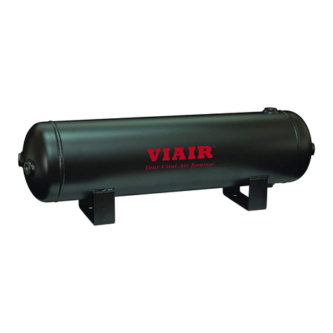
VIAIR 90011 User manual

1/4" QUICK CONNECT COUPLER 1pc.
QUICK CONNECT COUPLER COVER 1pc.
BULKHEAD UNION 1pc.
MOUNTING BRACKET
(self tapping screws included - 2pcs) 1pc.
LOCK WASHER 1pc.
BOLT 1pc.
1/4” M (NPT) TO 3/8” AIRLINE 90°
SWIVEL ELBOW FITTING 1pc.
1/4” M (NPT) TO 3/8” AIRLINE
STRAIGHT FITTING 1pc.
3/8" AIR LINE TUBING 15ft.
AIR SOURCE RELOCATION KIT
P/N’s 90011-90012
PARTS LIST:
IMPORTANT:
It is essential that you and any other operator of this
product read and understand the contents of this manual
before installing and using this product.
SAVE THIS MANUAL FOR FUTURE REFERENCE
USER MANUAL
PN 90011 PN 90012

AIR SOURCE RELOCATION KIT
TYPICAL INSTALLATION LAYOUT
P/N 90011-90012
15 Edelman
Irvine, CA 92618
949-585-0011
www.viaircorp.com
1. Air Tank (Not Included)
2. Drain Cock (Not Included)
3. 1/4” M (NPT) to 3/8” Airline 90°
Swivel Elbow Fitting
4. 3/8” O.D. Air Line Tubing
5. 1/4” M (NPT) to 3/8” Airline 90°
Straight Fitting
6. Bulkhead Union
7. Bulkhead Retaining Nut
8. Bulkhead Lock Washer
9. Mounting Bracket
10. Quick Connect Coupler
11. Quick Connect Stud (Not Included)
12. 35ft. Coil Hose (Not Included)
13. Quick Connect Cover
1
4
3
5 6 7 8 9
TO AIR COMPRESSOR
2
Fig. A
10
13
11 12

INSTALLATION INSTRUCTIONS (CONT’D)
INSTALLATION INSTRUCTIONS
The Pro Series Air Source Relocation Kit allows you to extend the air source from your air tank via air
line and ttings connections to a more accessible or convenient location using our unique bracket in
either Oval Style (PN 90012) or L Style bracket (PN 90011).
Step 1: Select location to relocate your Air Source
Select a convenient location to relocate your air source. Mount the Mounting bracket at your desired
location using the provided self-tapping screws. Insert the bulkhead union tting into the mounting
bracket and secure with the washers and nut (see Fig. A), insert the Quick Connect Dust Cap then
attach the Quick Connect Coupler to the 1/4" Female NPT tting of the bulkhead tting.
Step 2: Connecting 90 Degree PTC Elbow Fitting to Air Tank.
Before connecting the PTC Fitting rst make sure that the air tank is depressurized. Remove any
tting that is on the air supply port of the air tank. Install PTC Fitting onto air tank. (Fig. A)
Step 3: Install PTC Fitting onto the Bulkhead union. (See g. A)
Step 4: Routing Air Line From Air Tank to Bracket
Route air line from air tank to pre-selected air source location. Measure and cut air line to
appropriate length. Attach Airline to the PTC tting.
Step 5: Checking for Leaks
Use soap and water solution to test for leaks. If a leak is detected, the air line may not be pushed all
the way in or cut squarely, or ttings may not have been properly sealed and tightened. Repeat steps
needed to stop leaks.
Your Pro Series Relocation kit is ready to be used!
FEW WORDS ABOUT WORKING WITH AIR LINE TUBING...
a. When cutting air line tubing, always cut as squarely as possible. Use a hose cutter or razor blade.
b. To ease insertion of air line tubing onto ttings, lightly lubricate tip of air line tubing, or soak air line
tubing in warm water for about 5 minutes to soften air line.
c. When routing air line tubing, always remember to avoid sharp edges, heat source, and tight bends (Air
line must be routed at least 12" away from exhaust systems & components).

INSTALLATION INSTRUCTIONS
LIMITED WARRANTY:
VIAIR®Corporation warrants this product, when properly installed and under normal conditions of use, to be free from defects in workmanship and
materials for a period of one year from its original date of purchase. To receive warranty service or repair, please contact VIAIR®Corporation.
Returns should be made within one year of the date of purchase, after a Return Goods Authorization (RGA) number has been assigned by VIAIR®
Corporation. To obtain RGA, fax a copy of your receipt to (949) 585-0188. For complete warranty details, please visit: www.viaircorp.com/warranty
PLEASE NOTE:
THIS WARRANTY COVERS PRODUCT DEFECTS ONLY; IT DOES NOT COVER INCIDENTAL OR CONSEQUENTIAL DAMAGES AS RESULT OF MISUSE
OR ABUSE.
This Manual is proprietary to VIAIR®Corporation and no ownership rights are hereby transferred. No part of the Manual shall be used, reproduced,
translated, converted, adapted, stored in a retrieval system, communicated or transmitted by any means, for any commercial purpose, including without
limitation, sale, resale, license, rental or lease, without the prior express written consent of VIAIR®.
VIAIR®does not make any representations, warranties or guarantees, express or implied, as to the accuracy or completeness of the Manual. Users must be
aware that updates and amendments will be made from time to time to the Manual. It is the user’s responsibility to determine whether there have been any
such updates or amendments. Neither VIAIR® nor any of its directors, ocers, employees or agents shall be liable in contract, tort or in any other manner
whatsoever to any person for any loss, damage, injury, liability, cost or expense of any nature, including without limitation incidental, special, direct or
consequential damages arising out of or in connection with the use of the Manual.
All third party product names, logos, and brands are property of their respective owners. All company, product service
and trademark names are for identication purposes only. Use of these names, logos, and brands does not imply
ownership or endorsement.
15 EDELMAN • IRVINE, CA 92618
TEL: (949) 585-0011 • FAX: (949) 585-0188
www.viaircorp.com
R1-012323
© VIAIR® Corporation
This manual suits for next models
1
Table of contents
Other VIAIR Tank Equipment manuals
Popular Tank Equipment manuals by other brands

Graf
Graf Carat series Installation and maintenance instructions

Wilo
Wilo VBH Series Installation and operating instructions

Graf
Graf 160470 UPone 3 EW, 2000 L Assembly instructions

Primex
Primex MUNI Float installation instructions

Graco
Graco 234414 instructions

JohnDow Industries
JohnDow Industries JDI-AFT58 user manual