Endura XL100 Owner's manual

INSTALLATION, OPERATION & MAINTENANCE
WARNING!
Manual 40100-32 12/20
Canada
1-800-461-1771
U.S.A
1-888-461-5307
GRE ASE I NTERC EPT OR
GREA SEINTER CEPTOR
GRE AROT
PECRE
T
N
I
E
S
GREASE IN TER CEPTO R
GRE ASE I NTERCE PTOR
GREASE INT ERCE PTO R
GRE ASE INTER CEP TOR
GREASE INT ERC EPTO R
*
*
*
ASME A112.14.3 (TYPE A*& TYPE C)
& CSA B481.1
PDI G-101, ASME A112.14.3 TYPE A, AND NSF ES 15741
APPLICABLE TO XL75 AND XL100 GPM MODELS ONLY
Technical Support: tech-support@endurainterceptor.com
DONOTPRESSURETEST RISKOF
SERIOUSINJURY
As a plumbing appurtenance your Endura® grease
interceptor MUST be isolated from the drainage system in
the event that final drain testing or other system pressure
testing is required. DO NOT under any circumstances
subject your interceptor to pressure test (Air, Water
or Otherwise). This action will result in damage to
the unit, invalidate your warranty and could cause
serious bodily injury.
WARNING–SAFETYFIRST!
GREASE INTERCEPTORSAREHAZARDOUS
ENVIRONMENTS ANDMUSTNEVERBELEFT UNCOVERED
ANDUNATTENDED,EVENDURINGMAINTENANCE.
• All access covers MUST be fully and completely secured
• All required bolts MUST at all times be in place and well tightened
• Missing bolts MUST be reported to management and replaced immediately
•
•
Covers MUST meet the required load rating for the application (see the
Technical Information section)
Do NOT use alternate covers

- 2 -
GREASEINTERCE PTOR
GREAS E INTERCEPTOR
GREASEINTERCEPT OR
GREAS E INTERCEP TOR
MANUAL
LIFTING
POINTS
FACTORY PLUMBED
3-WAY OUTLET
SYSTEM
REMOTE PUMP READY
AIR & WATER TIGHT
EXTENSION SYSTEM
INTEGRATED LIFTING
LOCATIONS
CLOSED RIBS FOR
FLOTATION RESISTANCE
INTEGRATED TIE DOWN
LOCATIONS
CORRUGATED WALLS
FOR STRENGTH
LOAD RATED
COVER & FRAME
CUT TO SUIT RISER
EXTENSION
BUILT-IN HEIGHT
ADJUSTMENT
AIR BALANCED
ENVIRONMENT
TANK PROFILE
RESISTS
FLOTATION
Features Overview
About Your Purchase:
The Endura® XL grease interceptor and it associated products are the latest addition to the proven line of Endura®
Grease Management products.
We have spent many thousands of hours in the development of Endura® XL, our aim being simple – to produce
the industry’s best Hydromechanical Grease Interceptor.
From the ground up, Endura® XL has been‘Engineered for Easy’. Working with distributors, installers, engineers,
the feedback gained and rolled it into one comprehensively designed solution to meet as broad a range of these
requirements as possible.
Endura® XL is the most widely evaluated and approved hydromechanical interceptor in the current marketplace,
being successfully tested by independent third parties to meet all requirements of PDI G-101*, ASME A112.14.3
(Type A* & C) / NSF ES15741* and CSA B481.1.
*PDI G-101, ASME A112.14.3 TYPE A, AND NSF ES 15741 APPLICABLE TO 75 AND 100 GPM MODELS ONLY

- 3 -
Glossary of Terms
Table of Contents
HGI: Industry abbreviation for Hydromechanical
Grease Interceptor. By denition an HGI is designed to use
managed ow, air entrainment and specically designed
features to provide an enhanced level of separation
eciency, removing non petroleum FOG (Fats, Oil and
Grease) from a transition ow of waste water, generated by
commercial foodservice activities (Restaurants, Cafeterias,
Institutional Kitchens , Sandwich Shops and Coee houses
for example). HGI’s are performance tested for eciency of
grease separation based on National Standards.
Operational Cost Index =1
GGI: Industry abbreviation for Gravity Grease
Interceptor. By denition a GGI has a minimum of 350USG
capacity and in operation 500USG to 1500USG of capacity
are most common. No ow control device. Separation
of FOG based on capacity and retention time of water
(minimum 30 min. to exchange volume). At this time no
performance Standards are published for GGI’s.
Operational Cost Index HGI = 5 GGI = 10+
GRD: Industry abbreviation for Grease Removal
Device. Designed rstly as an HGI, a GRD uses a heat source
and a timed or sensor based skimming (or draw-o ) device
to remove accumulated FOG from the separation chamber
into an external container for collection and disposal. These
units require daily maintenance for management of food
solids. Operational Cost Index HGI = 2.5 GGI = 5
AHJ: Authority Having Jurisdiction. This can be
one or more government departments - for example plan
check/review, building, plumbing, pretreatment, sewer and
waste water. Bottom line...those who enforce the rules and
regulations.
Cost Index: A way of indicating the relative cost
of dierent types of interceptor to each other for broad
comparison purposes. This includes product purchase,
installation cost and typical maintenance.
25% Rule: The rule of thumb, sometimes mandated
by jurisdiction, used to determine frequency of pump
out for GRAVITY GREASE INTERCEPTORS. The 25% refers
to the combined volume or retained FOG and food solids
which shall not exceed 25% of the working volume of the
interceptor. This rule should not typically be applied to HGI’s
particularly those with extended capacity.
Air Entrainment: Mixing of air with Inuent using
a ow control device. Air and grease are attracted to each
other, the air wanting to separate more easily than grease.
Because they become mixed together the air increases the
eciency of separation.
Euent: Waste water containing little to no FOG,
being discharged out of the interceptor.
Inuent: Waste water containing uncontrolled
and variable levels of FOG based on the nature and
practices of the foodservice operation.
Separation Chamber: Zone inside the
interceptor where grease separates from water and is
retained.
– Available online – Mobile Friendly
– Best Management Practices
BMP
Page
Features Overview 2
Glossary 3
Quick Start Installation Guide 4
Technical Information 6
Installation Specifications 8
Installation 11
Installation - Flow Controls 12
Remote Pump (optional) 13
Page
Installer Checklist 14
Operation 15
Maintenance 16
Pumper Checklist 18
Trouble Shooting 19
Frequently Asked Questions 20
Warranty 23
Registration Card 24

Quick Start Guide
- 4 -
Quick Start Guide
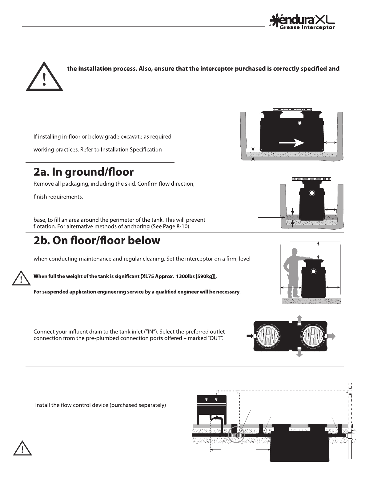
Before you begin, be sure to review this document in full for important information regarding
sized for the intended installation. Be sure to reference and be familiar with local code and
municipal FOG Program requirements. The Authority Having Jurisdiction (AHJ) can be your
best friend and your worst enemy.
1. Prepare your
installation area
to accommodate the interceptor and ensure safe
section of this document (See Page 8-10).
3. Select preferred outlet connection
Side connection is accessed by removal of the caps supplied, that cap then being
used to seal the end outlet.
lower in and level interceptor accounting for anticipated surface
Note: For installations where high ground water is anticipated,
once located pour at least 8”of concrete on top of your prepared
Remove all packaging including the skid. Locate the interceptor so as to allow for accessibility
surface ensuring tank is equally supported.
XL100/ XL150 Approx. 2150lbs [975kg])
A minimum safety factor of 2 shall be applied in calculation/design.
Concrete Anchor
Base (if anchoring
is required)
Min.
6"
Inle Ot utlet
Min.
12"
Min.
12"
Min.
8"
6" Minimum Base
of Crushed aggregate
material approximately
3/4" size rock, pea
gravel or sand
Ensure adequate roomfor
piping connections
and inspections
G ET
NI
E
S
A
ER P
ECR TR
O
T
NI
E
S
A
ER
GCR
ERO
TP
E
G E
T
NI
E
S
A
ER P
ECR TRO
CR
E
T
NI
E
S
A
ER
GRO
TP
E
OUTSIDE -
SIDE - OUT
END - OUT
IN
Max. 25ft
(for PDI)
PDI
External Flow
Controlinstallation
Cleanout
Cleanout
FCD Air Intake
Sink
Inlet Outlet
4. Installations with External Flow Control
(PDI G-101/ASME A112.14.3 - Type A)
See page 6 for
cleanout part numbers
Min. Base
Anchoring
(if required)
Level end to end
Flow Direction
Level side to side
For PDI G-101/ASME A112.14.3 (External Flow Control)–
upstream, after the last branch connection discharging to the
interceptor. A maximum of 25ft from last branch discharge
to the entry of the interceptor is required to meet published
recommendations. See Page 12 for connection formats.
Plumbing code typically requires provision of a cleanout
to grade immediately before and after the inlet and outlet
connections.

Quick Start Guide
- 5 -
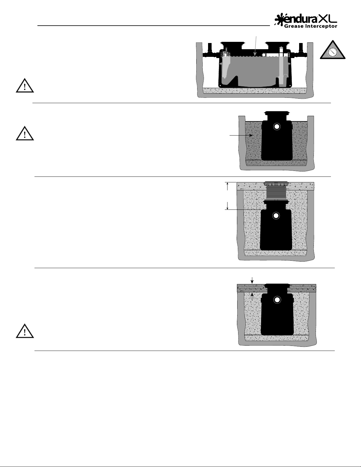
Fill with water to static level
Continue fill of
Crushed aggregate
material approximately
3/4" size rock,
pea gravel or sand
6. Replace cover(s) and backll
Replace cover(s) and protect with cardboard or similar
during back lling. Backll per specication (See Page 8).
If installing Remote Pump option do so now (See Page 13)
5. Fill tank
Fill tank with water to static water level. This provides stability
and crush resistance during backlling. Check connections made
for any leaks.
For inspection testing DO NOT PRESSURE the tank. Plug
lines inside interceptor to test upstream and downstream
integrity.
7. Riser Extensions (optional)
Depending on your application, extend the tank risers
(using 40100AX35) to grade/oor level. Be sure to account
for nishing. (Refer to Manual 40100X35-8 – Riser Extension
Installation Guide)
8. Finish to grade / oor
For in ground applications with vehicular trac, the upper 8” requires a
reinforced concrete slab. Refer to the Installation Specication section of
this document (See Page 8-9). This details backll materials and concrete
reinforcement requirements.
If installing in internal application with tiled oor, ensure adequate
protection to prevent mortar from covering bolts, and/or entering
around cover perimeter.
9. Completion documentation
Having completed installation and successful inspection, hand-over to the client all installation documentation, with page 14
completed. Fill out your sections of the Limited Lifetime warranty registration (See Page 24).
If submitting on behalf of your client you can do so at www.EnduraWarranty.com or by sending to the locations shown on
the back cover of this document.
72”
Maximum
height
Reinforced concrete pad for traffic rated installations
8"
WARNING!
X
DO NOT
PRESSURE TEST.
RISK OF SERIOUS
INJURY.
For Spec See Page 8-9

140150ARDB
Internal Flow Control Plate - 150gpm 1 40150-21
Technical Information
- 6 -
4
21
3
6
5
10
11
9
7 8
Mechanical
Joint couplings
(by others)
All images are for illustrative
purposes only. Actual parts
Air Balance/
Sampling Cap
is ESSENTIAL to
the operation of
the interceptor.
Endura® XL Tank Components
Item # Description Qty Part #
1 Endura XL 75 gpm tank 4” Spigot connections with S Rated Lids 1 4075A04
Endura XL 75 gpm tank 4” Spigot connections with M Rated Lids 1 4075A04M
Endura XL 75 gpm tank 4” Threaded connections with S Rated Lids 1 4075A04T
Endura XL 75 gpm tank 4” Threaded connections with M Rated Lids 1 4075A04MT
Endura XL 100 gpm tank 4” Spigot connections with S Rated Lids 1 40100A04
Endura XL 100 gpm tank 4” Spigot connections with M Rated Lids 1 40100A04M
Endura XL 100 gpm tank 4” Threaded connections with S Rated Lids 1 40100A04T
Endura XL 100 gpm tank 4” Threaded connections with M Rated Lids 1 40100A04MT
Endura XL 150 gpm tank 4” Spigot connections with S Rated Lids 1 40150A04
Endura XL 150 gpm tank 4” Spigot connections with M Rated Lids 1 40150A04M
Endura XL 150 gpm tank 4” Threaded connections with S Rated Lids 1 40150A04T
Endura XL 150 gpm tank 4” Threaded connections with M Rated Lids 1 40150A04MT
Parts
Overview
Access Covers
CSA B481.0Type‘M’
G rade
.625" R aised Cover
C over F lus h to Gra de
lb
g
2000 lb
907 kg
M
10,000 lb
4536 kg
S
2 1 4075ARDB
140100ARDB
3 Internal Flow Control Plate - 75gpm 1 4075-21
Internal Flow Control Plate - 100gpm 1 40100-21
4 Endura XL Air Balance/Sample Port Cap 1 40100-33
5 Cover Seal 2 40100-4
6 5/16 - 18 x 1.5” Socket Set Screw with blue Loctite 8 40100-42
7240100ARCS
8240100ARCM
External Flow Control - for PDI/ASME Type A applications
9 Endura XL External Flow Control - 75gpm 1 4044275
Endura XL External Flow Control - 100gpm 1 40442100
Parts Purchased - Recommended Installation
10 4”2-Way Cleanout - Sewer x Sewer x DWV 1 414150BC
4” 2-Way Cleanout - Sewer 1 414155BC
Parts Purchased - Remote Pump Application
11 Remote pump pipe seal (optional) 1 40100TPS3
Access covers with retained bolts
supplied with Interceptor

Endura XL150
40150A04
40150A04M
150 (9.5)
96.3%
160˚F
(71˚C)
S10,000 lb (4536 kg)
M2000 lb (907 kg)
S20,000 lb (9072 kg)
M4000 lb (1814 kg)
283 lb
(128 kg)
257 gal
(973 L)
4”
300 (136)
1097 (498)
Technical Information
- 7 -
Contractor shall install a Endura® XL Hydromechanical Grease Interceptor (HGI), Part No. 40100A04
❑
40100A04M
❑,, ,40150A04 ❑
40150A04M
❑, 4075A04 ❑, 4075A04M ❑(See page 6 table), and rated to 100GPM ❑
150GPM ❑75GPM ❑
(Indicate as Applicable) independently
❑ (Tick if required).
72” regardless of the application and when requiring Riser Extension, the installing contractor will extend the opening device according
* PDI G-101 AND NSF ES 15741 APPLICABLE TO 75 AND 100 GPM MODELS ONLY.
*
to manufacturers published instructions. The outlet system will provide facility for connections to be made perpendicular to the inlet
shall provide mechanical joint connectors or requisite materials to connect the grease interceptor to the drainage system, additionally
making adequate provision for management of food debris and solids.
Interceptor shall be furnished with two (2) access covers, maximizing internal visibility for inspection and maintenance when removed.
These covers shall be capable of withstanding a proof load of 20,000lbs, approved for application at temperatures from -20˚F to +100˚F
(-29˚C to +38˚C) and will be mechanically secured when operational.
The interceptor tank shall be constructed with seemless engineered thermoplastics, evaluated and approved to the material performance
requirements of CSA B481.0
The interceptor shall additionally; operate with an air-balanced environment to equalize variation in internal pressures being controlled
and maintained with an appropriately sized air balance means; be supported by a Lifetime Warranty against manufacturing defect.
❑, 4044275A ❑
40442100AT ❑, 4044275AT ❑
the interceptor, being vented and installed according to manufactures instructions and the currently published version of PDI G-101.
Interceptor will be located within 25ft developed pipe run of the last connected appliance for standard compliance. Where applicable
discharge appliances and the interceptor inlet.
Air Intake can be connected to building
vent system or be independently to the
atmosphere based on local code.
• Flow Control
• Flow Control
Pipe by
others
• Air Intake Tee
• Air Intake Tee
Connection
Iron Pipe Size
(Solvent weld)
4” h x h
A 6.13”
(155.7mm)
B 6.84”
(173.7mm)
C -
4” h x h
3.19”
(81mm)
5.04”
(128mm)
2.72”
(69.1mm)
Capacities
External
Flow Control
Dimensions
For full CAD, BIM Models
and 3 Part Master Format
Specs visit www.arcat.com
Search keyword “endura”
CAD BIM SPECS
®
Endura XL75 Endura XL100
• Part Number 4075A04
4075A04M
40100A04
40100A04M
US Gallons Per Minute - GPM (L/Sec) 75 (4.74) 100 (6.3)
A112.14.3) >98% >98%
Operating Temperature Capabilities 160˚F
(71˚C)
160˚F
(71˚C)
Cover Load Rating- CSA B481.0
S10,000 lb (4536 kg)
M2000 lb (907 kg)
S10,000 lb (4536 kg)
M2000 lb (907 kg)
CSA B481.0
Min. Test Load for Approval
S20,000 lb (9072 kg)
M4000 lb (1814 kg)
S20,000 lb (9072 kg)
M4000 lb (1814 kg)
Unit Weight (Empty) 233 lb
(106 kg)
283 lb
(128 kg)
Liquid Capacity 158 gal
(598 L)
257 gal
(973 L)
Connection size
(mechanical joint only)
4” 4”
Min. Grease Capacity - lb (kg) 150 (68.2) 200 (90.8)
Grease Capacity Actual
(ASME A112.14.3) - lb (kg)
† NSF ES 15741
559 (253)†1058 (480)†

- 8 -
4"
the unit footprint
Concrete Pad
must extend
18" outside
45.00°
2 1/2" Min.
18" outside the unit footprint
Concrete Pad must extend
8"
4"
Top View
Rebar
Finished Grade
Rebar
CONCRETE SLAB DETAIL FOR TRAFFIC LOADING
(INTERIOR OR EXTERIOR)
Elevation View
(Connecting pipeand fittings by others)
For unit details seespecification sheet for selected unit
SIDE VIEW DETAIL
(INTERIOR OR EXTERIOR)
EXCAVATION AND
BACKFILL DETAIL
DIMENSIONS
72”
Maximum
height
Native soil
Concrete slab
Crushed aggregate
material approximately
3/4" size rock, pea gravel
or sand
6”Min. base crushed
aggregate material
approx. 3/4" size rock,
pea gravelor sand
95 proctor.
unit (by others)
Clean outto grade
Flow
on outlet pipe of each
tee (414155BC)
2-Way cleanout
tee (414155BC)
2-Way cleanout
mechnical joint
coupling (byothers)
Standard 4”
mechnical joints
coupling (by others)
Standard 4”
on inletpipe of each
Clean outto grade
unit (by others)
Flow
72”
Maximum
height
50”
26”
22”
14
29”
79”
32” 39.5”
59”
43”
Risers to grade
MATL: PE
DESCRIPTION:
DWG BY: L.S.
DWG NUMBER: XL75BGT
4075A04 4075A04T4075A04M 4075A04MT
Endura XLgreaseinterceptors are rated and suppliedwith an internal flow control system already in place.
They do not require an external flow control system or air intake vent unless specified by local code requirements
or being operatedas a PDI G-101 installation. Endura XL grease interceptors are only to be installed in the
manner and for the application shown. Consult local codes for separate trapping requirements, cleanout locations
and additional installation instructions. Full instructional information supplied with every interceptor.
NOTES:
PROPRIETARY AND CONFIDENTIAL - © Canplas 2017
Canplas Industries Ltd.
500 Veterans Drive, Box 1800
Barrie, Ontario,
Canada L4M 4V3
CAN: 1-800-461-1771 USA: 1-888-461-5307
DATE: JAN 2020 REV: 1.3
Endura brand products
manufactured by
Canplas Industries Ltd.
Endura® XL - EXTERIOR BELOW GRADE INSTALLATION INSTRUCTIONS
BELOW GRADE INSTALLATION INSTRUCTIONS
1. EXCAVATION
1.1
1.2 Width and length of excavation shall be minimum 12”greater thanthetank dimensionsonall sides.
1.3 Depth ofexcavation shall be at least 6”deeper than tank bottom.
1.4 IMPORTANT:Maximum burial depth 6ft (72”) measured from the air balance channel(EnduraXLLogo)
1.5 Set the tank on well-packed crushed aggregatematerial approximately3/4”size rock, peagravelor
sand.When setting Endura® XL units theymust be levellaterallyand longitudinally.
1.6
anchoring may however be necessary as determined bythespecifying engineer.Tie-downlocations are
incorporated tothe tank and can be used in conjunction withcoated stainless steelcableand an
applicable anchormethod based on subsoil. Specific requirements to be determined by specifyingengineer.
2. BACKFILLING & FINISHED CONCRETE SLAB (TRAFFIC LOADRATED)
AASHTO 304 – H20(16,000lbs) and approved to CSAB481.0 Class‘S’-20˚F to +100˚F (-29˚C to +38˚C)
2.1 Preparation of sub grade per local jurisdictionalrecommendations.
2.2 Stabilize and compactsub grade to 95% proctor per Excavation informationabove.
2.3
.
2.4
ade level.
2.5
2.6 Placeminimum 6”aggregate base beneathpoured structuralslab.Aggregate shouldbe 3/4”sizerock or
pea shingle.
2.7
refer to localspecifying engineer recommendations and/orlocalcode requirements.Note: Concrete slab
dimensions shown arefor illustration purposes only.
2.8 Concrete to be 28 day compressive strengthto 4000 PSI. Reinforcementwith No.4rebar (1/2”) grade 60
steel per ASTM A615: connected with tie wire. Rebar tobe 2½”fromedge ofconcrete.Rebar spacing
12”grid. 4”spacing around access openings.
3. PIPING CONNECTIONS
3.1
AllEndura®XLGrease Interceptors aremanufactured with no hub connections.Threaded connectionsare
3.2 Locallyapproved mechanical joint (MJ) couplings are used toconnecttheinlet andoutlet pipingtothe
3.3 Makesystem piping connections usinglocally approved MJcouplings installing to manufacturer’s
belowthe water level.DO NOTPRESSURE TEST – Risk of serious Injury or Death.
3.4 DONOTdecrease pipe diameter across the unit (i.e. 4 inchinlet,3inchoutlet). Ifthe pipingsystem
installed in compliancewithlocal code.
4 EXTENSION RISERS (Optional)
4.1 Endura® XLExtension Risers provide amaximumof35”extensionper riser. Based on maximum
installationdepth up toa maximum of 72”depth of burialcanachieved (see 1.4above), adding
ExtensionRisers (or partthereof) during installation.Risers are cuttolength onsiteto suit installation.
4.2
4.3
4.4
mechanism. Cut and extend a length of 1½”DWV pipe per instructions supplied.
4.5
cleanly byhand or mechanical means using guide rings molded intotheriser to give cleanstraightcut.
4.6 Fit riser seal provided over the cut edge of the riser and locate frame (supplied) over the sealmaking
sureit is fully seated.Secure with lag screwsprovided using the pre-drilled locations in frame.
4.7 Repeat process for additionalriser if/as required.
4.8
DWV and secure the support to the framewiththe screwprovided. Solvent weld a1½”venttee ontop
of thepipe toactas ahandle.
4.9

- 9 -
Endura XL grease interceptors are rated and supplied with an internal flow control system already in place.
They do not require an external flow control system (PDI G-101 listing not available for 150 GPM Models)
or air intake vent unless specified by local code requirements or being operated as a PDI G-101 installation.
Endura XL grease interceptors are only to be installedin the manner and for the application shown.
Consult local codes for separate trapping requirements, cleanout locations and additional installation instructions.
Full instructional information supplied with every interceptor.
NOTES:
PROPRIETARY AND CONFIDENTIAL - © Canplas 2017
4"
the unit footprint
ConcretePad
must extend
18" outside
45.00°
2 1/2" Min.
18" outside the unit footprint
Concrete Pad must extend
8"
4"
Top View
Rebar
Finished Grade
Rebar
CONCRETE SLAB DETAIL FOR TRAFFIC LOADING
(INTERIOR OR EXTERIOR)
Elevation View
(Connecting pipe and fittings byothers)
Forunit details see specification sheet for selected unit
SIDE VIEW DETAIL
DIMENSIONS
26”
22”
14”
34.5”
48.5”
84.5”
50”
72”
Maximum
height
72”
Maximum
height
78”
48.5”
32”
Native soil
Concrete slab
Crushed aggregate
material approximately
3/4" size rock, peagravel
or sand
unit (by others)
Cleanout to grade
Flow
on outlet pipe of each
tee (414155BC)
2-Way cleanout
tee (414155BC)
2-Way cleanout
mechnical joint
coupling (by others)
Standard 4”
mechnical joints
coupling (by others)
Standard 4”
on inlet pipe of each
Clean out to grade
unit (by others)
Flow
Risers to grade
6”Min. base crushed
aggregate material
approx. 3/4" size rock,
pea gravelor sand
95 proctor.
(INTERIOR OR EXTERIOR)
EXCAVATION AND
BACKFILL DETAIL
Endura® XL - EXTERIOR BELOW GRADE INSTALLATION INSTRUCTIONS
BELOW GRADE INSTALLATION INSTRUCTIONS
1. EXCAVATION
1.1
1.2 Width and length of excavation shall be minimum 12”greater thanthetank dimensionsonall sides.
1.3 Depth ofexcavation shall be at least 6”deeper than tank bottom.
1.4 IMPORTANT:Maximum burial depth 6ft (72”) measured from the air balance channel(EnduraXLLogo)
1.5 Set the tank on well-packed crushed aggregatematerial approximately3/4”size rock, peagravelor
sand.When setting Endura® XL units theymust be levellaterallyand longitudinally.
1.6
anchoring may however be necessary as determined bythespecifying engineer.Tie-downlocations are
incorporated tothe tank and can be used in conjunction withcoated stainless steelcableand an
applicable anchormethod based on subsoil. Specific requirements to be determined by specifyingengineer.
2. BACKFILLING & FINISHED CONCRETE SLAB (TRAFFIC LOADRATED)
AASHTO 304 – H20(16,000lbs) and approved to CSAB481.0 Class‘S’-20˚F to +100˚F (-29˚C to +38˚C)
2.1 Preparation of sub grade per local jurisdictionalrecommendations.
2.2 Stabilize and compactsub grade to 95% proctor per Excavation informationabove.
2.3
.
2.4
ade level.
2.5
2.6 Placeminimum 6”aggregate base beneathpoured structuralslab.Aggregate shouldbe 3/4”sizerock or
pea shingle.
2.7
refer to localspecifying engineer recommendations and/orlocalcode requirements.Note: Concrete slab
dimensions shown arefor illustration purposes only.
2.8 Concrete to be 28 day compressive strengthto 4000 PSI. Reinforcementwith No.4rebar (1/2”) grade 60
steel per ASTM A615: connected with tie wire. Rebar tobe 2½”fromedge ofconcrete.Rebar spacing
12”grid. 4”spacing around access openings.
3. PIPING CONNECTIONS
3.1
AllEndura®XLGrease Interceptors aremanufactured with no hub connections.Threaded connectionsare
3.2 Locallyapproved mechanical joint (MJ) couplings are used toconnecttheinlet andoutlet pipingtothe
3.3 Makesystem piping connections usinglocally approved MJcouplings installing to manufacturer’s
belowthe water level.DO NOTPRESSURE TEST – Risk of serious Injury or Death.
3.4 DONOTdecrease pipe diameter across the unit (i.e. 4 inchinlet,3inchoutlet). Ifthe pipingsystem
installed in compliancewithlocal code.
4 EXTENSION RISERS (Optional)
4.1 Endura® XLExtension Risers provide amaximumof35”extensionper riser. Based on maximum
installationdepth up toa maximum of 72”depth of burialcanachieved (see 1.4above), adding
ExtensionRisers (or partthereof) during installation.Risers are cuttolength onsiteto suit installation.
4.2
4.3
4.4
mechanism. Cut and extend a length of 1½”DWV pipe per instructions supplied.
4.5
cleanly byhand or mechanical means using guide rings molded intotheriser to give cleanstraightcut.
4.6 Fit riser seal provided over the cut edge of the riser and locate frame (supplied) over the sealmaking
sureit is fully seated.Secure with lag screwsprovided using the pre-drilled locations in frame.
4.7 Repeat process for additionalriser if/as required.
4.8
DWV and secure the support to the framewiththe screwprovided. Solvent weld a1½”venttee ontop
of thepipe toactas ahandle.
4.9 DATE: JAN, 2020 REV: 1.3
MATL: PE
DESCRIPTION:
DWG BY: L.S.
DWG NUMBER: XL100BGT
Canplas Industries Ltd.
500 Veterans Drive, Box 1800
Barrie, Ontario,
Canada L4M 4V3
CAN: 1-800-461-1771 USA: 1-888-461-5307
Endura brand products
75 GPM AND 100 GPM MODELS
manufactured by
Canplas Industries Ltd.
40100A04 40100A04M 40100A04T 40100A04MT
40150A04 40150A04M 40150A04T 40150A04MT
**
*

- 10 -
External
Flow Control
If Required
External
Flow Control
If Required
External
Flow Control
If Required
External
Flow Control
If Required
External
Flow Control
If Required
OUT
OUT
OUT
OUT
GREASEI NTERCEP TOR
GREASEINTE RCEPTOR
GREASEI NTERCEPTOR
GREASEI NTERCEPTOR
OUT
GREASEINTER CEPTOR
GREASEINTE RCEPTOR
GREASEI NTERCEPTOR
GREASEINT ERCEPTOR
R
GAE RET
NIES ECPT OR
R
G RE
T
N
I
E
S
AE E
CPTOR
GRAE RET
NIES E
CPTOR
R
GAE R
E
T
NI
ES P
E
CTOR
R
G AE RETNIES T
PE
C OR
GRAE RETN
I
E
S E
CPTOR
R
G RETN
IE
S
AE E
CPTOR
R
GA
EE
C
R
E
T
N
IE
S PTOR
E
R
GAES R
E
T
NI
CPETOR
R
G EA E
SI TN RECP
ETOR
AE
R
G E
T
N
IES R CEPTOR
R
G AE SRETNI
E PE
CTOR
R
G AE SRET
N
IE P
E
CTOR
ETNI
E
S
A
E
R
GRCPETOR
E
R
G A ESI ET
N RCEPTOR
E
R
G A E
SR
ET
N
I
C T
PE OR
OUT
OUT
IN
IN
R
G EA E
SR
ETNI C T
PE OR
R
GEAE
SI
T
NR
ECT
P
EOR
R
G AE ET
NI
E
SRCEPTOR
R
G AE SR
E
T
NI
E PE
CTOR
R
G AE SRE
T
N
I
ECP
ETR
O
A
E
R
GE
T
N
IES R CPETR
O
R
GEA E
S I
E
T
N R C P
ETOR
E
R
G A E
SRE
T
N
I CPET R
O
IN
IN
IN
IN
R
GAESR
ET
N
I
ECPET RO
R
GAE ET
N
IE
SRCPET RO
R
G EA ES I
E
T
NRCPE OT R
R
GEAES RET
N
I
CP
ETRO
R
GA
ESRE
T
N
I
E CP
ETR
O
R
G AE ETNIES RCP
ETR
O
R
G EA E
SI
E
T
NRCPETR
O
E
R
G A ES RETNI CP
ETR
O
GREASEINTERCEPTO R
GREASEI NTERCEPTOR
GREASEINTERCEPT OR
GREASEINT ERCEPTOR
OUT
IN
GREASEINTERCEPTOR
GREASEINTER CEPTOR
GREASEINTERCEPTOR
GREASEI NTERCEPT OR
GREASEINT ERCEPTOR
GREASEINTE RCEPTOR
GREASEINTERCEPTOR
GREASEINTER CEPTOR
IN
GREASEINTERCEPTOR
GREASEI NTERCEPTOR
GREASEINTERCEPTOR
GREASEINTERCEPTO R
GREASEINTERCEPTOR
GREASEINTERCEPTOR
GREASEINTERCEPTOR
GREASEINTER CEPTOR
OUT
GREASEINTERCEPTOR
GREASEI NTERCEPTOR
GREASEI NTERCEPTOR
GREASEINT ERCEPTOR
GREASEI NTERCEPTOR
GREASEINTER CEPTOR
GREASEINTERCEPTOR
GREASEINTE RCEPTOR
IN
R
G R
ET
N
IES
A
ECEPTOR
R
GAE R
E
T
N
I
ES E
CPTOR
R
G AE SRE
T
N
IE CR
OT
PE
R
GA
E ETN
I
E
SRCPETOR
R
GEA ES C
RE
T
N
I PETOR
R
G EA E
SI T
NC
R
ET
PE OR
R
G A
E ET
N
IES RE
CPTOR
R
GA
ESET
N
I
ERP
E
CTOR
R
G EA E
SI T
N R
ECP
ETOR
R
G EA ES R
E
T
N
I
CT
PE OR
GRAE RE
T
N
I
E
S EC PTOR
R
GEA PE
C
RE
T
N
IE
STOR
OUT
IN
GREASEINTERCEP TOR
GREASEI NTERCEPTOR
GREASEINTERCEPT OR
GREASEI NTERCEP TOR
GREASEINT ERCEPTOR
GREASEINTE RCEPTOR
GREASEINTERCEPTOR
GREASEI NTERCEPT OR
OUT
IN
GREASEINT ER E
CPTOR
GREASEI
NTERCEPTOR
G E
RASEINTE RCEPTOR
GREASEINTERE
CPTOR
GREASEI NTERE
CPTOR
GREASEI
NTE R E
CPTOR
GREASEI
N TERCEPTOR
G E
RASEINTER CEPTOR
G E
RASEINT ER E
CPTOR
GREASEINTE RCEPTOR
GREASEI
NTER E
CPTOR
GREASEI
NT ERE
CPTOR
G E
RASEINTE RCEPTOR
GREASEI
NTERCEPTOR
GREASEINTERCEPTOR
GREASEI NTERCE PTOR
4075A04 4075A04M 4075A04T 4075A04MT
MATL: PE
DESCRIPTION:
DWG BY: L.S.
DWG NUMBER: XLSP
40100A04 40100A04M 40100A04T 40100A04MT
40150A04 40150A04M 40150A04T 40150A04MT
C/OC/O
C/O
C/ CO /O C/ CO /O C/O
C/OC/OC/OC/O
C/O
C/O
C/O C/O C/O
C/O C/O C/O
C/O
C/OC/OC/OC/O
C/OC/O
C/O
C/OC/O
C/O
C/O
External
Flow Control
If Required
External
Flow Control
If Required
External
Flow Control
If Required
External Flow Control If Required
Flow Control
Cleanout Air Intake
External
Flow Control
If Required
C/O
C/OC/O
C/OC/O
C/ CO /O
C/ CO /O
C/ CO /O
External
Flow Control
If Required
External
Flow Control
If Required
External
Flow Control
If Required
External
Flow Control
If Required
External
Flow Control
If Required
External
Flow Control
If Required
External
Flow Control
If Required
GR NIESA
E R
E
TC P
E T R
O
GR N
I
E
SA
E E
TRCP
ETR
O
GREAN
I
E
SR
E
TC P
ETR
O
GRNI
E
S
A
ER
E
TCP
ETR
O
Endura XL grease interceptors are rated and supplied with an internal flow control system already in place.
They do not require an external flow control system or air intake vent unless specified by local code requirements
or being operated as a PDI G-101 installation*. Endura XL grease interceptors are only to be installed in the
manner and for the application shown. Consult local codes for separate trapping requirements, cleanout locations
and additional installation instructions. Full instructional information supplied with every interceptor.
NOTES:
PROPRIETARY AND CONFIDENTIAL - © Canplas 2017 DATE: JAN, 2020 REV: 1.3
Canplas Industries Ltd.
500 Veterans Drive, Box 1800
Barrie, Ontario,
Canada L4M 4V3
CAN: 1-800-461-1771 USA: 1-888-461-5307
Endura brand products
manufactured by
Canplas Industries Ltd.
Series Installation:
· S
· A
· W
upstr
upstr
Important:
· Adequateprovisionfordrainaccess isessential.Twowaycleanoutsextendedtogradearerequired
bef
pipelengthisgreaterthan36”
· ConnectionstotankmadewithapprovedMechanicalJoint(MJ)couplingsormalepipethread
dependen
· Manufacturer’sinstructionssuppliedwithunitsmust befollowed.
(purchasedseparately) willbeinstalledupstream afterlast
branchconnectionnofurtherthan25ftfrominterceptor
414155BC Cleanout
414155BC
Cleanout
External Flow
Control If
required
External Flow
Control If
required
External Flow
Control If
required
External Flow
Control If
required
414226BC
6 x 4 Ext.
Reducer
414130BC
Double Wye
414194BC
45˚ Bend -
Street
414155BC
Cleanout
414174BC 90˚ Bend
Recommended
Components:
Parallel Installation:
· P
application and should be followed.
· In
60% of r
· Where External Flow Control is not required or preferred,
the par
· Where preferred or required, installation of a correctly
r
in
Flow control shall be accessible (from grade as applicable)
once operational.
· Adequate provision for drain access is essential. Two way
cleanouts extended to grade are required before all tank
inlets and following all outlets. Access between tanks is also
recommended if pipe length is greater than 36”
· Connections to tank made with approved Mechanical
Joint (MJ) couplings or male pipe thread dependent on unit
· Manufacturer’s instructions supplied with units must
be followed.
Access Covers:
supplied with CSA B481.0 Type‘S’
covers. For Internal/ light vehicular
(2000 lb Safe Working Load)
2 no. XL75 – SERIES - 75GPM, 1118 lbs Grease Capacity.
2 no. XL75 – PARALLEL
Up to 150GPM, 1118 lbs
Grease Capacity.
2 no. XL100 – PARALLEL Up to
200GPM, 2116 lbs Grease Capacity.
2 no. XL150 – PARALLEL Up to
300GPM, 2194 lbs Grease Capacity.
3 no. XL100 – PARALLEL Up to
300GPM, 3174 lbs Grease Capacity.
3 no. XL150 – PARALLEL Up to
450GPM, 3291 lbs Grease Capacity.
4 no. XL100 – PARALLEL Up to 400GPM,
4232 lbs Grease Capacity.
4 no. XL150 – PARALLEL Up to 600GPM,
4388 lbs Grease Capacity.
2 no. XL100 – SERIES - 100GPM, 2116 lbs Grease Capacity.
2 no. XL150 – SERIES - 150GPM, 2194 lbs Grease Capacity.
3 no. XL150 – SERIES - 150GPM, 3291 lbs Grease Capacity.
3 no. XL100 – SERIES - 100GPM, 3174 lbs Grease Capacity.
4 no. XL150 – SERIES - Up to 150GPM, 4388 lbs Grease Capacity.
4 no. XL100 – SERIES - Up to 100GPM, 4232 lbs Grease Capacity.
4 no. XL150 – SERIES - Up to 150GPM, 4388 lbs Grease Capacity.
4 no. XL100 – SERIES - Up to 100GPM, 4232 lbs Grease Capacity.
Canplas
Part#
Description QTY
414155BC SDR35 Two Way Cleanout - HxHxH
414174BC SDR35 90˚ Bend - Street - HxSpg
414130BC SDR35 Double Wye - HxHxHxH
414226BC SDR 35 6 x 4 Ext. Reducer HxSpg
414194BC SDR 35 45˚ Bend - Street
4044275 Endura® XL 75gpm Flow Control
40442100 Endura® XL 100gpm Flow Control
*PDI G-101, ASME A112.14.3 TYPE A, AND NSF ES 15741 APPLICABLE TO 75 AND 100 GPM MODELS ONLY

Installation Instructions
Installation
Scope of Application:
petroleum Fats, Oil and Grease as a by-product of commercial foodservice activities. The Endura® XL interceptor models are
tested and rated.
Accessibility:
Installations shall be made in such a manner that full access for maintenance and cleaning is maintained once the interceptor is
commissioned. A zone based on a column measured 3ft out from the cover perimeter and extending 7ft vertically is recommended.
Inlet (IN) and Outlet (OUT) connections are indicated on the interceptor itself. Ensure that the interceptor is in the correct
Location:
the source and the interceptor. Adequate provision for rodding and service access is particularly important upstream of the
interceptor. Please refer to local code requirements.
Drain lines servicing the interceptor shall be laid at a minimum ¼”per foot fall and with more gradient where possible.
Piping Connections:
The primary bulkhead-style connections (in-line) of Endura® XL are injection molded in Polyproylene (PP). PP does not accept
solvent weld cement and will not provide a serviceable connection. DO NOT SOLVENT WELD these drain connections.
Best practice and most codes typically require the use of Nationally or locally approved Mechanical Joint (MJ) couplings for the
Flow Control:
to meet the requirements of PDI G-101, assuming that the applicable venting and installation criterial are met (See Page 12).
Trapping:
equivalent, in compliance with applicable plumbing code requirements.
Venting:
The installation of the interceptor shall be vented downstream in accordance with local code requirements - typically within10 ft max.
• Air Gap/ Air Break
• Flow Control Device
Indirect Connections/ Air Gap/Air Brake :
Some local jurisdictions require warewashing installations to be
made on an indirect basis incorporating an air gap.
This is to prevent the back up of contaminated waste water
control device provides a restriction within the system it must be
incorporated before the indirect connection to prevent the risk of
installation of the air intake tee is optimal.
*Dependent on jurisdiction
WARNING–SAFETYFIRST!
GREASEINTERCEPTORS AREHAZARDOUS
ENVIRONMENTS ANDMUSTNEVERBELEFT UNCOVERED
ANDUNATTENDED, EVENDURINGMAINTENANCE.
• All access covers MUST be fully and completely secured
• All required bolts MUST at all times be in place and well tightened
• Missing bolts MUST be reported to management and replaced immediately
•
•
Covers MUST meet the required load rating for the application (see the
Technical Information section)
Do NOT use alternate covers
WARNING–SAFETYFIRST!
ALLINSTALLATION SHALL BECONDUCTEDUNDERTHE
APPLICABLE HEALTH AND SAFETY REGULATIONSIN
FORCE WITHIN THATJURISDICTION.
Plumbing operatives shall be adequately trained and appropriately
licensed to conduct the installation. All installations will be made
respective and in compliance with applicable plumbing code and any
locally published by-laws. Installation and approval of the same is
Having Jurisdiction (AHJ).
- 11 -

Installation - Flow Controls
- 12 -
Max. 25ft
FCD Air Intake
PDI
External Flow
Control. Located
as close as possible to
the last fixture
Cleanout
Sink
Flow
External Flow
Control:
When installed with an
External Flow Control, the
seal shown above are removed
during installation.
will now be performed by a separate
device that will be installed upstream
from the interceptor. This is located as
close as possible to the appliances and
branch connection to the main drain
line connected to the interceptor. The
remain accessible for maintenance and
The location of the cleanout should be
recorded in you Installer Hand Over
Check List (See Page 14)
is important that it be opened and checked
periodically (min. twice annually) to ensure
there is no build up or blockage occurring that
Remove
plate
Remove
Flow Controls
Depending on preference or requirement
Endura® XL can be operated with an internal
Internal Flow Control:
of the hydromechanical grease
interceptor and its function.
Flow
control
plate
Flow
control
seal
Inlet
*
*
*PDI G-101, ASME A112.14.3 TYPE A, AND NSF ES 15741 APPLICABLE TO 75 AND 100 GPM MODELS ONLY

Installation - Remote Pump (Optional)
- 13 -
GREA SEINTERCEPT OR
GREASEINTERCEPTOR
GREASEINTERCE PTOR
GREASE INTERCEPT OR
45˚ cut
XL75
36”
XL100
41”
Remote Pump (Optional):
Endura® XL incorporates a method for installation of a Remote
Pump function where desirable or required. The simplicity of
minimal materials. The installation is based on the use of a 3”
DWV Sch40 pipe which is passed into the tank by means of a 3”
diameter tank penetration seal (Part# 40100-TPS3”).
1. Cut the end of a 3” Sch40 DWV pipe (ABS or PVC by
preference) at an angle that is no less than 45 degrees.
2. GOOD PREPARATION OF THIS PIPE END IS ESSENTIAL TO
AVOID DAMAGING THE RUBBER SEAL WHEN BEING
INSTALLED. The outer edges must be chamfered to at least
45 degrees around the full length of the pipe end.
3. Now measure from the end of the pipe to the following
length depending if you are installing an XL75 or XL100 /
XL150 respectively. For XL75 pipe length 36”; For XL100 /
XL150 pipe length 44” (Fig A)
4. On the top surface of the tank at the center position and on
either side of the air balance channel are two “Remote
Pump Ready” details, both of which include a drill center
(Fig. B). Select which of the two locations best suits your
application and using a 4” diameter hole saw, open the
respective hole.
Remote
pump outlet
optional
locations
Fig. A
Fig. B
5. Fit penetration tank seal (Part# 40100-TPS) into
the opening prepared and lubricate well using silicone
pipe lubricant.
6. As the orientation of the pipe wheninstalled is important,
mark or identify on the top of the pipe so as to indicate
that the angled face of the pipe will be facing laterally
across the interceptor when installed. i.e. the angled face
is pointed toward the opposite tank wall.
7. Take your prepared length of pipe and liberally apply
silic
ensuring that the angled surface is also well lubricated.
8. Introduce the pipe to the rubber seal and with even
pressure and a rotating motion, push the pipe through
the seal and into the tank. Once onto the full diameter
of the pipe apply more lubricant to the next 12-18” and
continue to push the pipe downward into the tank until
the tip bottoms out, with the angled face in the correct
position.
9. Develop your pump out line connecting to the pipe
stub now extending from the tank using long sweep
ing provision for adequate
cleanout access as required. All joints must be solvent
welded or of threaded format.
Maximum developed pipe run shall be no greater than
30 feet with a vertical rise of 8 feet max.
10.At the extent of the remote pump system where the
pumping service will be connected, typically a capped
ovided to allow
compatibility with vacuum service connection.
GREASE INTERCEPTOR
GREASE IN TERCEPTO R
GREASE INTERCEPTOR
GREASEINTERC EPTOR
Max.
30ft
Max.
8ft
45˚ cut faces
opposite tank wall
Long
Sweep
Bends Tank
Penetration
Seal
(40100TPS3)
See
Step
10

Installer Handover Checklist
- 14 -
Installation made by (Company) ___________________________________________________________
Installer (Name) __________________________________________________________________
Installer Contact (Tel) _________________________________
Completed on (Date) _________________________________
Model Installed: Lid:
❑ Endura XL100 (40100A04 (T) / 100GPM)
❑ Endura XL150 (40150A04 (T) / 150GPM)
❑ M-Rated
❑ S-Rated
❑ Endura XL75 (4075A04 (T) / 75GPM)
Installation Format: ❑ On-Floor ❑ In Floor - Inside Building ❑ Floor Below (eg. basement)
❑ In-Ground - Outside building
❑ Yes ❑ No (See Page 8-9)
Flow Control Format: ❑
❑ External (Upstream of Interceptor)
If External Flow Control …
Internal Flow Control plate removed ❑ Yes ❑ No (See Page 12)
Flow Control Location(s) ____________________________________________________
Connections & Cleanouts (Mark where installed):
Extension Risers added: ❑ Yes - if Yes, approx. length of riser installed: _________in /m
❑ No
Flow Control Handle Extended: ❑ Yes ❑ No (See Riser Extension Instructions))
Air Balance/Sampling Cap in place: ❑ Yes ❑ No (If No, Replacement required. See Page 16)
Entered Information on Warranty Page ❑ Yes ❑ No
Have feedback? Email us at… feedback@endurainterceptor.com
Installer Handover Checklist
The following checklist completed by your installer provides key information regarding your Endura® XL grease interceptor
and the way it has been installed. If it is not completed contact your installer and complete with them by phone or other
appropriate means.
GETNI
E
S
A
E
RP
ECR T R
O
T
N
IES
A
ER
GCR
ER
O
TP
E
GETN
I
E
S
A
ER P
ECR T R
O
CRET
N
I
E
S
A
E
RG R
O
TPE
Cleanout
OUT
IN
Cleanout
Cleanout
External
*
*
*
Flow
Control
Cleanout
*PDI G-101, ASME A112.14.3 TYPE A, AND NSF ES 15741 APPLICABLE TO 75 AND 100 GPM MODELS ONLY

Operation
Operation
IMPORTANT:
Dynamic
Interceptor is uniquely accessible once in service.
Having removed the cover above the inlet, a simple
pull/push motion on the handle opens and closes
the front shell, allowing access for maintenance and
cleaning. This action also opens the inlet drain to
its full diameter allowing the upstream drains to be
cleaned without obstruction.
and value even when buried at full depth below
grade. Refer to installation instructions for riser
extension.
Food Solids and Debris:
Solids
retention
area
Accessibility:
It is the responsibility of the restaurant operator to maintain
safe, clear and unobstructed access to the interceptor at all
access in the event of an issue and for the regular pumping of
the interceptor required to keep it in good working order.
Pull up
to open
Visually inspect
or clean inlet and
required
WARNING–SAFETYFIRST!
GREASEINTERCEPTORS AREHAZARDOUS
ENVIRONMENTS ANDMUSTNEVERBELEFT UNCOVERED
ANDUNATTENDED, EVENDURINGMAINTENANCE.
• All access covers MUST be fully and completely secured
• All required bolts MUST at all times be in place and well tightened
• Missing bolts MUST be reported to management and replaced immediately
•
•
Covers MUST meet the required load rating for the application (see the
Technical Information section)
Do NOT use alternate covers
WARNING–SAFETYFIRST!
ENSURE THAT ANYOPERATIVESOR EMPLOYEES THAT
ATTEND TO THEGREASE INTERCEPTOR AREADEQUATELY
PROTECTED. AS AMINIMUM IT ISRECOMMENDED THAT
PROTECTIVE GLOVES, EYEWEAR AND A MASK ARE
PROVIDED ANDUSED.
Clearance
Min. 3ft
180˚
Min. 7ft
clearance
- 15 -
Endura® XL is designed to manage up to 15% of its volume for solids management. Remember
however that your grease interceptor is an engineered system that is notdesigned to
accommodate large amounts of solid material.This will impact the operational capacity and
performance of the unit andcause the foul odors often associated with grease interceptorsif not
removed regularly.
It is strongly recommended that a solids interceptor be installed upstream of the grease interceptor and that all entry points to the drains
kitchen practice recommends that all plates, crockery, pans, etc., be scraped to remove lose food debris prior to washing. Again sinks should be
operated with the respective screens.
If you are experiencing frequent issues in regard to blockages or accumulation in your interceptor you must address the appropriate kitchen
practices. DO NOT MODIFYTHE INTERCEPTOR OR MEANS OF FLOW CONTROL IN ANY MANNER. Doing so voids the performance approval

Operation / Maintenance
- 16 -
Ensure that any operatives or employees that attend to the
grease interceptor are adequately protected. As a minimum
it is recommended that protective gloves, eyewear and a
mask are provided and used.
Where a third party contractor or service is responsible
for the regular maintenance of the interceptor (strongly
recommended) it is their responsibility not only to ensure
that their own protective practices and procedures are
maintained and followed, but that they also protect those
with access to the vicinity of the interceptor when it is
Air Balanced Operation:
Endura® XL is designed to function based on a balance air environment.
During the maintenance of your interceptor, it is important to check
that the breather hole in the outlet vent (see diagram) is unobstructed.
The smallest restriction can drastically impact the performance of your
interceptor and can cause the accumulated contents of the interceptor
to be discharged to the downstream drain system particularly if
access/breather cap must be relocated upward as close as possible to
the underside of the cover to maintain its function.
IF YOU DO NOT SEE A GREY CAP ON TOP
OF THE OUTLET SYSTEM, CONTACT YOUR
INSTALLER/MAINTENANCE CONTRACTOR
IMMEDIATELY AND IF NECESSARY
PURCHASE A REPLACEMENT.
Air Balance/
Sampling Cap is
ESSENTIAL to the
operation of the
interceptor and
must be kept free
of debris.
If extending height,
sampling/air balance
cap must be raised also.
Air Balance Hole
Maintenance
IMPORTANT:
Regular Removal of Fat, Oil and Grease:
Due to the capacity of your Endura® XL Grease Interceptor it is necessary to have a licensed and locally approved service
provider manage the regular removal, cleaning and disposal of the Fats, Oil and Grease that is captured in your interceptor.
rule of thumb your interceptor should be cleaned every 8-12 weeks. You should anticipate a minimum of 4-6 cleans per year.
BMP
BMP
undergoing maintenance. In addition they will be stewards
to premises management issues with for example, but not
limited to, interceptor operation, damages, spills, etc.
IMPORTANT:
maintenance (See Maintenance Procedures – Pg 17). You
should consider your facility to be in partnership with the
management that is mandated to protect your business,
your community and the environment.
Regular Removal of Fat, Oil and Grease:
Due to the capacity of your Endura® XL Grease Interceptor
it is necessary to have a licensed and locally approved
service provider manage the regular removal, cleaning and
disposal of the Fats, Oil and Grease that is captured in your
interceptor.
WARNING–SAFETYFIRST!
GREASE INTERCEPTORS ARE HAZARDOUS
ENVIRONMENTSANDMUST NEVER BELEFT UNCOVERED
ANDUNATTENDED, EVENDURING MAINTENANCE.
• All access covers MUST be fully and completely secured
• All required bolts MUST at all times be in place and well tightened
• Missing bolts MUST be reported to management and replaced immediately
•
•
Covers MUST meet the required load rating for the application (see the
Technical Information section)
Do NOT use alternate covers.

Maintenance
- 17 -
Maintenance Procedures:
Removal of Access Cover:
The covers that provide access to the XL interceptors
are retained with four (4) standard hex head bolts which
are removed with a ½” socket/driver. These bolts have a
retraining washer on the reverse to prevent them falling
out of their location when the cover is removed from the
interceptor.
Covers incorporate pry points for ease of removal.
Each cover weighs approximately 22lbs (10kg) so take care
when lifting and moving the cover. Always set aside the
cover on a at surface when removed.
On reinstallation visually check the seal recessed in the
underside of the cover and when satised ret the cover
being sure not to overtighten the bolts. Maximum torque is
80-100 ft/lb.
Access to the Dynamic Inlet Bae
(Internal Flow Control where used):
The Dynamic Inlet Bae is a unique element of Endura® XL
allowing access to the internal surfaces for maintenance,
inspection and cleaning.
To open the bae, take a rm grip on the handle and pull
vertically upward. The handle will move approximately 6” in
the vertical direction. In doing so the front shell of the bae
moves away from the xed rear portion providing access to
the internal ow control plate (where tted).
The ow control plate is securely retained but is intended
to be removable during installation, should an external ow
control be the preferred format of installation.
Once open, visual inspection can be made inside the bae.
Any debris is best removed with a low pressure source of
warm water – approx. 38˚C (100˚F)
To close the bae, push vertically downward on the handle
until it returns to the full closed and locked position
Drain Cleaning/Inspection:
For cleaning and inspection of the upstream drain, it is
strongly recommended that the inlet bae be in the open
position. This will reduce the risk of damage to the internal
ow control (where tted) by rooting or other equipment.
Access to the Outlet Well:
Although essentially a closed area, the outlet system is able
to be accessed by removal of the Sampling/Air Balance
Cap. Once removed the 4” vertical pipe is able to be visually
inspected all the way to the bottom (with the unit pumped
out), and in the event of any accumulation can be cleaned
by vacuum or pressurized water, either withdrawing debris
out or back into the tank respectively.
Pumping and Cleaning:
The complete removal of grease and water should be done
at every pump out. This ensures all solids, grease and water
are removed allowing visual inspection and removal of any
residue.
Any residue is best removed with a hot water source rinsing
the walls and internal components into the tank before
making a nal vacuum extraction.
The tank must be re-lled to static
water level on completion of pumping.
An interceptor cannot function
without water.
Remote Pump Out (Optional):
An installation tted with the remote pumping option oers
convenience for the pumper and the restaurant operator,
but also presents risk.
Where installed and operated with a remote pump facility,
the interceptor should be physically opened and inspected
at least every third pumping, or twice a year, whichever
is sooner. This is to ensure that the internal parts are in
good working order and that there is no undue build-up
of residue or solids remaining in the tank once it has been
emptied. This also presents opportunity to open and inspect
the inside of the inlet bae system, and clean/inspect the
outlet well. Any residue will be removed with a warm water
source.
BMP
Remember: Every installation is dierent based on factors such as operational hours, menu, seasonality
of business, sta changes, etc. As a rule of thumb your interceptor should be cleaned every 8-12 weeks. You
should anticipate a minimum of 4 cleans per year.
Pull up
to open
Push
down to
close
Internal Bae
in closed
position
Internal
Bae in open
position for
inspection

Pumper Checklist
- 18 -
Interceptor Operating at: __________________________________________ (Enter Facility Name)
Address: __________________________________________
__________________________________________
__________________________________________
Serviced By (Name): _______________________________
Company: __________________________________________________________
Company Contact (Tel): _______________________________
About this Pump-Out:
Service Date: _______________________________
Format: ❑ Remote Pump ❑ Full Access (Covers Removed)
Last Full Access Pump? ______________________________
Note: At a minimum of every 3rd remote pump or twice annually (whichever is sooner) full access cleaning and
inspection is required.
Interceptor Fully Pumped (Water/FOG & Solids): ❑ Yes ❑ No
Approx. Volume of Waste Removed: _____________________ Gallons/Liters
Inlet Bae Opened/Inspected ❑ Yes ❑ No
Flow Control Checked/Cleaned ❑ Yes ❑ No
Note: The ow control device (internal or external), shall be inspected and cleaned a minimum of every 3rd
pump or twice annually (whichever is sooner)
Cover(s) secured on completion of Pumping? ❑ Yes ❑ No
Important Note: If covers are in an area that is accessible to the public, always check to ensure that covers are
fully secured even if you did not remove the cover(s) as part of this pump-out.
Any Concerns, Issues or Comments to Report: _____________________________________________________
___________________________________________________________________________________________
___________________________________________________________________________________________
___________________________________________________________________________________________
Have feedback?
Email us at… feedback@endurainterceptor.com
Pumper Checklist:

Trouble Shooting
- 19 -
Trouble Shooting
Troubleshooting
Symptoms Cause Corrective Actions
Strong pungent odour. • Cover not replaced and/or properly secured
• Cover seal missing or damaged
• Insucient or incorrect venting
• Insucient cleaning frequency
• Secure cover fully - check that there is no dirt/debris in
the threaded insert
• Replace appropriate seal
• Verify installation is made per manufacturer’s instructions
and local plumbing code
• Reduce interval between cleaning – 6 to 8 weeks is
typical for extended capacity, but each installation is
dierent
Sink or drain has backed
up with water • Interceptor maintenance is overdue
• Accumulation of grease/debris between kitchen
and interceptor
• The ow control orice is blocked
• The ow control and grease trap was improperly sized
• The grease trap is full of solids and/or grease
• The grease trap close to, at or beyond its capacity of
solids and/or grease
• Seek emergency plumbing assistance to remove
restriction/blockage. Consider moving the interceptor
closer to the kitchen
• Isolate drain, open accessible ow control and
clear blockage
• Close the ball valve or plug the sink and remove the
obstruction by removing the ow control access lid.
• Install a properly sized grease interceptor
• Increase cleaning frequency
I think I have
missing parts • Parts have been removed or lost during prior servicing • Check exploded drawing in this manual to conrm
the parts that are supposed to make up your
interceptor model
Excessive solids / grease
accumulation •The Grease Interceptor is full/requires cleaning
• Food waste on pots, plates & utensils are not being
scraped into the garbage & is being ushed down the
sink. This food waste accumulates on the bottom of
the tank
• Grease interceptor has remained dormant for a
period of time
• Increase cleaning frequency
• Train sta as to importance of good kitchen
practices
• Install a solids interceptor in or upstream of
the interceptor. Use screens on oor drains
and sinks
• Contact a licensed service professional to
re-commission your interceptor
My indirect connection
leaks all over the oor
when I empty the sink(s)
• Incorrectly installed/located ow control device • Move ow control device to a location upstream of the
indirect connection
The XL inlet bae is not
working/is broken • Damaged/broken parts • For technical assistance email
tech-support@endurainterceptor.com
mark your email - High priority
I can’t get the bolts to
thread back in.
• Bolt cross threaded
• Grit / debris in threaded insert • Examine and clear and debris in threaded insert.
Use light lubricating oil as applicable.
• If thread is damaged replace insert.
Need Technical Support?
Canada
1-800-461-1771
Email: tech-support@endurainterceptor.com
U.S.A.
1-888-461-5307

150
150
9.46
300
136
Frequently Asked Questions
- 20 -
Frequently Asked Questions
Following are just a few of the common terms and questions we receive regarding
Grease Management.
How do I size a Grease Interceptor correctly?
A grease interceptor can be sized using two primary methods - Flow rate or capacity
Sizing by Flow Rate
Table A - Procedure for Sizing Grease Interceptors
STEP FORMULA EXAMPLE
1by multiplying length x
width x depth A sink 24” long by 20” wide by 12” deep.
Cubic content: 24 x 20 x 12 = 5,760 cu in
(61.0 x 50.8 x 30.48 cm3)
2Determine capacity in gallons.
1 gallon = 231 cu in Contents in gallons:
5,760 / 231 = 24.9 gallons
(94,451.42 / 1,000 = 94.45 litres)
3Determine actual drainage load.
with water as the items being washed displace about 25% of
Actual drainage load:
.75 x 24.9 = 18.7 gallons
(0.75 x 94.45 = 70.84 litres)
4In general, good practice dictates a one minute drainage peri-
od; however, where conditions permit, a two minute drainage
Flow rate = Actual Drainage Load
Drainage Period
(70.84 / 1 min. = 70.84 l.p.m.)
(70.84 / 2 min. = 35.42 l.p.m.)
5Select Interceptor.
falls between two sizes, select the larger of the two
interceptors.
For a one minute drainage period:
For a two minute drainage period:
Table B -Metric conversions based on PDI sizes
PDI Size 4 7 10 15 20 25 35 50 75 100
Flow Rate US Gallons per Minute (gpm) 4 7 10 15 20 25 35 50 75 100
Flow Rate Liters per Second (L/Sec) .25 .44 .63 .95 1.26 1.58 2.20 3.16 4.74 6.3
Grease Capacity Min. (lb) 8 14 20 30 40 50 70 100 150 200
Grease Capacity Min. (kg) 3.63 6.35 9.07 13.61 18.14 22.68 31.75 45.36 68 91
Interceptor is considered mandatory.
second (L/Sec).
Fixture Capacity:Most commonly used and recommended method for Hydromechanical Grease Interceptors. This
wastewater through the interceptor. Units are expressed in Gallons Per Minute (gpm).
20gpm Grease Interceptor.
Pipe Size:
Pipe
Diameter Maximum
Flow Rate
(gpm)
Size of interceptor
1-minute drain
period (gpm)
Size of interceptor
2-minute drain period
(gpm)
2-inch 20 20 10
3-inch 60 75 35
4-inch 125 150 75
For additional Sizing Tools and
Maintenance Interval Optimization,
use our Endura® Calculator online or
email: tech-support@endurainterceptor.com
Other manuals for XL100
1
This manual suits for next models
8
Table of contents
Popular Water Filtration System manuals by other brands

Delta Water Engineering
Delta Water Engineering PFS-M Installation & operating guide

DeVilbiss
DeVilbiss HFRL-508 Service manual

Jandy
Jandy AquaPure Installation and operation manual

Watts
Watts OneFlow OF240-4 Installation, operation and maintenance manual

prodac
prodac Magic External Filter 2 manual

SMC Networks
SMC Networks FH100 Series Operation manual

Clear2O
Clear2O CCT2000 owner's manual

Donaldson
Donaldson AFS-BH430-IBF-ICA instructions

AQUAPHOR
AQUAPHOR DWM-101 installation guide

Doulton
Doulton Ceramic Twin Undersink Installation & maintenance guide

norweco
norweco HYDRO-KINETIC 3780L Installation and operation manual

Panasonic
Panasonic ET-RFC100 operating instructions