EnduroSat S-BAND / UHF TRANSCEIVER User manual

USER MANUAL
Communication Module

S-BAND / UHF TRANSCEIVER – USER MANUAL
ENDUROSAT
2
1 Change log ........................................................................................................................ 3
2 Acronyms list ..................................................................................................................... 4
3 System Overview ............................................................................................................... 5
4 Highlighted Features.......................................................................................................... 6
4.1 Transceiver S-Band .................................................................................................................6
4.2 Transceiver UHF ......................................................................................................................6
5 System Description............................................................................................................ 7
6 Electrical Characteristic ..................................................................................................... 9
6.1 Transceiver S-Band .................................................................................................................9
6.2 Transceiver UHF ......................................................................................................................9
7 RF Characteristics ........................................................................................................... 10
7.1 Transceiver S-Band ...............................................................................................................10
7.2 Transceiver UHF ....................................................................................................................14
8 Connector Pinout............................................................................................................. 16
8.1 Connectors Location .............................................................................................................16
8.2 H1 - Stack Connector ............................................................................................................17
8.3 H2 - Stack Connector ............................................................................................................17
9 Mechanical Drawing ........................................................................................................ 19
10 Envinronmental And Mechanical Testing ........................................................................ 20
11 Materials And Processes ................................................................................................. 20
12 Handling And Storage ..................................................................................................... 20
13 Warnings.......................................................................................................................... 21
S-BAND / UHF TRANSCEIVER – USER MANUAL
ENDUROSAT
3
S-BAND / UHF TRANSCEIVER
USER MANUAL
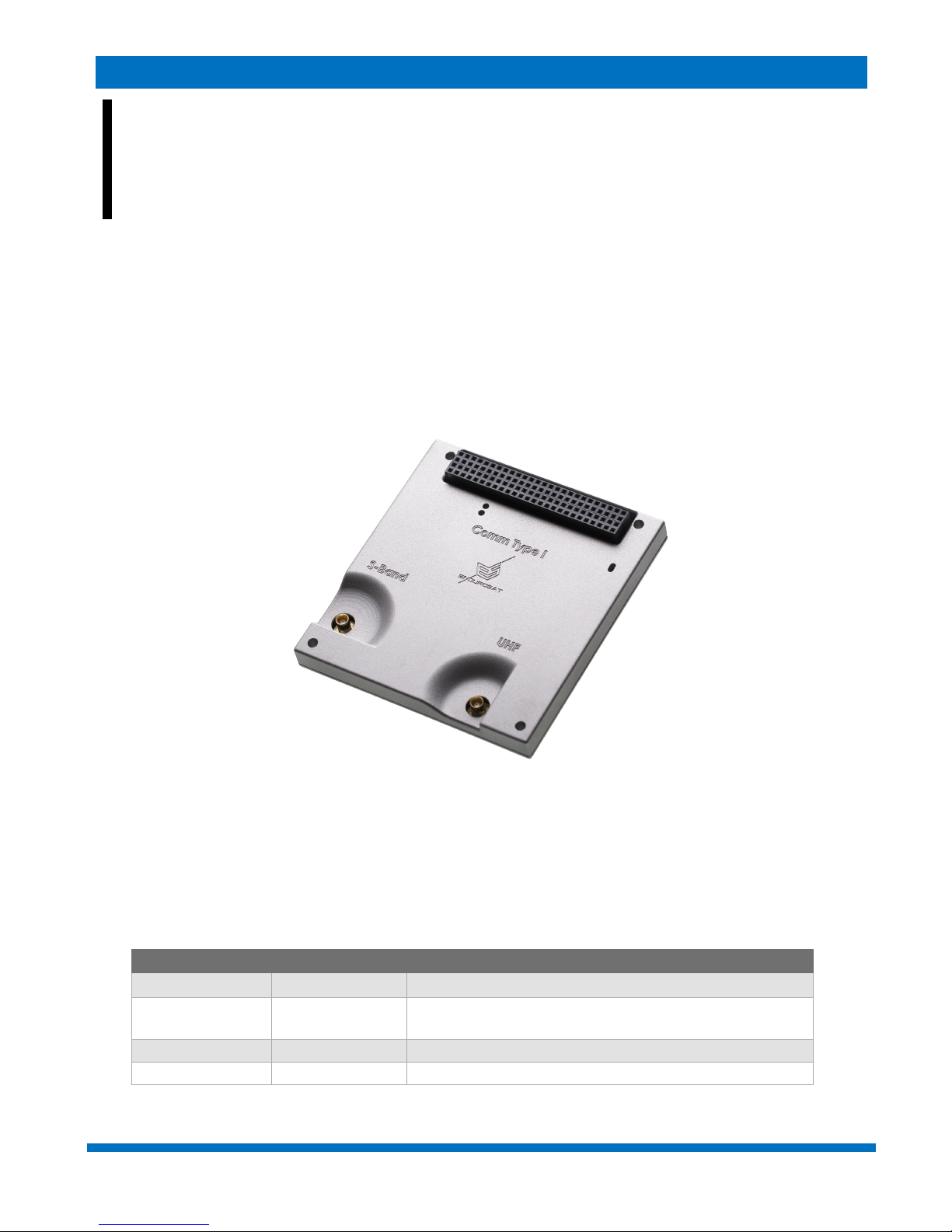
This user manual is specially designed to detail the EnduroSat S-Band / UHF Communication module
functions and features.
Please read this manual before unpacking and using the module to ensure safe and proper use.
Figure 1 - Communication module
1 CHANGE LOG
Date
Version
Note
27/06/2016
Rev 1
15/07/2016
Rev 1.2
Minor text and format changes. Updated pinout
connectors, weight, block diagrams.
04/11/2016
Rev 1.3
Electrical characteristics paragraph
18/11/2016
Rev 1.4
Corrections sensitivity, power consumptions

S-BAND / UHF TRANSCEIVER – USER MANUAL
ENDUROSAT
4
2 ACRONYMS LIST
BER
Bit Error Rate
BPF
Berkeley Packet Filter
ECSS
European Cooperation Space Standardization
EMI
Electromagnetic interference
ESA
European Space Agency
ESD
Electrostatic Discharge
GEVS
General Environmental Verification Standard.
GFSK
Gaussian Frequency Shift Keying
GND
Ground
I2C
Inter-Integrated Circuit
LDO
Low-DropOut
LNA
Low-Noise Amplifier
MCU
Microcontroller Unit
MCX
Micro Coaxial
PCB
Printed Circuit Board
PER
Packet Error Ratio
RF
Radio Frequency
SPI
Serial Peripheral Interface
UART
Universal Asynchronous Receiver/Transmitter
UHF
Ultra-High Frequency
USART
Universal Synchronous Asynchronous Receiver Transmitter
USB
Universal Serial Bus

S-BAND / UHF TRANSCEIVER – USER MANUAL
ENDUROSAT
5
3 SYSTEM OVERVIEW
This S-Band / UHF communication module features dual frequency communication via totally
independent half-duplex transceivers on a single PCB. Both bands are in the amateur range and can
be configured in the whole allocated spectrum – 430-440 MHz and 2400-2480 MHz for the UHF and
S-Band respectively. Furthermore, they feature configurable data rates, which can be programmed
on-orbit – 2 for the UHF and 4 for the S-Band.
The output power can also be tuned in order to maximize the power budget depending on orbit
altitude, ground station and desired minimum elevation angle for communication. The primary
designation for the UHF is telemetry and telecommand while the S-Band is more suitable for payload
data downlink at higher bit rate. Nevertheless, both transceivers can be used for both downlink and
uplink and provide redundancy to each other. There are two separate microcontrollers that manage
the two transceivers thus enabling them to work independently and even simultaneously. Reed-
Solomon encoding of the data increases the reliability of the link. The device is fully encapsulated in
an aluminum shell that takes care of heat dissipation from the power amplifiers and significantly
reduces the EMI.

S-BAND / UHF TRANSCEIVER – USER MANUAL
ENDUROSAT
6
4 HIGHLIGHTED FEATURES
4.1 Transceiver S-Band
• Frequency range: 2400-2480 MHz;
• Typical transmit power: 2 W (33 dBm);
• Power amplifier efficiency: >40%;
• Power supply: 5 V +/- 0.25 V;
• Typical current consumption: up to 1.35 A;
• Frequency stability: +/- 10 ppm;
• Data rate: 250 kbps – 2 Mbps;
• Sensitivity: -94 to -86 dBm;
• Interfaces: SPI (SLAVE).
4.2 Transceiver UHF
• Frequency range: 430-440 MHz;
• Maximum transmit power: 1.5 W;
• Power amplifier efficiency: >70%;
• Power supply: 3.2 – 3.4 V;
• Typical Current consumption: up to 0.82 A;
• Frequency stability: +/- 2.5 ppm;
• Data rate in the air: 2000 – 12000 bps;
• Sensitivity: -113 to -121 dBm;
• Interfaces: UART @ 9600bps / I2C (optional);
• Type: Half-duplex;
Weight
114g
External dimensions
90.2x95.9x25.2mm
S-BAND / UHF TRANSCEIVER – USER MANUAL
ENDUROSAT
7
5 SYSTEM DESCRIPTION
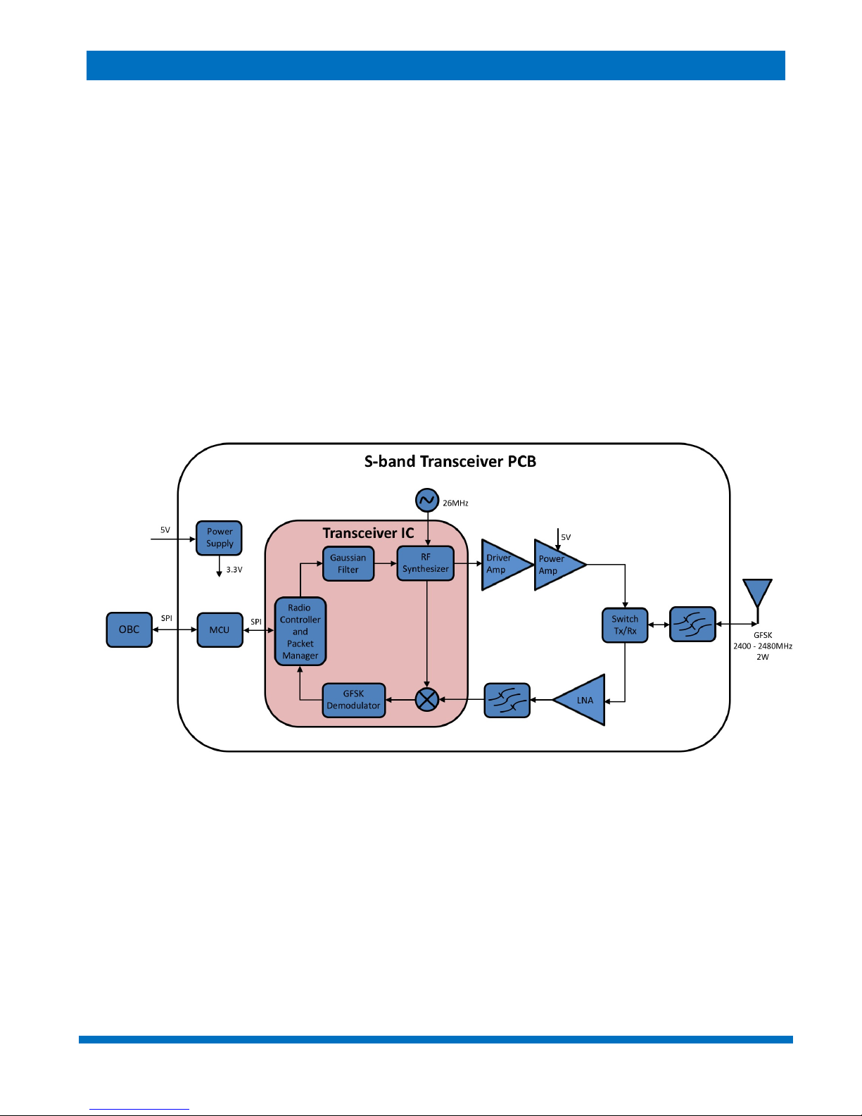
The S-band transceiver works in the frequency range 2400 – 2480 MHz with GFSK modulation. In
the core of this S-band transceiver there is a high performance IC which is a zero-IF transceiver. It is
responsible for the output signal forming and also down converting and demodulating of the input
signal. It contains radio controller and packet manager which makes it very flexible. For its integrated
frequency synthesizer and system timing it uses a 26 MHz reference signal. In the Tx signal chain
there is a RF driver amplifier followed by a PA which boosts the output signal up to 2 W. In the Rx
signal chain there is a LNA followed by BPF. There is also аTx/Rx switch since the device is half-
duplex. The communication with the OBC (or payload) is accomplished by SPI interface of the MCU.
The supply voltage to the transceiver must be 5V ±0.25V and is directly connected to the PA. There
is a LDO, which reduces the voltage for the rest of the schematic to 3.3 V. The connector used is
PC-104 suitable for stackable configurations. The connector for the antenna is MCX.
Figure 2 - Block Diagram of the S-Band transceiver
S-BAND / UHF TRANSCEIVER – USER MANUAL
ENDUROSAT
8
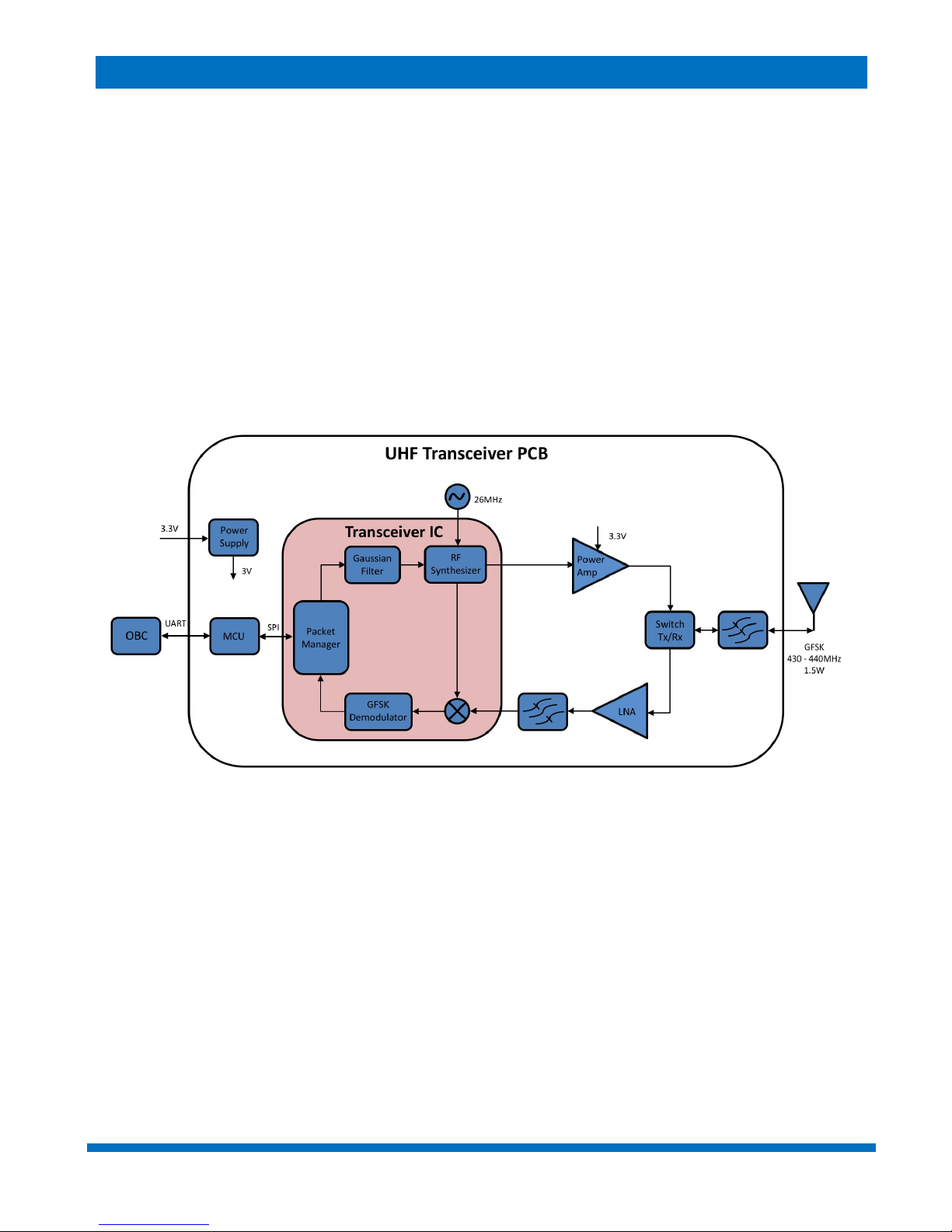
The UHF transceiver works in the frequency range 430 – 440 MHz with GFSK modulation. In the
core of this UHF transceiver there is a high performance IC which is a zero-IF transceiver. It is
responsible for the output signal forming and also downconverting and demodulating of the input
signal. It contains very flexible packet manager that handles the data packets. The reference signal
source for its integrated frequency synthesizer is at 26 MHz. There is a PA in the Tx signal chain,
which boosts the output signal up to 1.5 W. In the Rx signal chain there is a LNA followed by BPF.
There is also a Tx/Rx switch since the device is half-duplex. The communication with the OBC (or
payload) is accomplished by UART / I2C interface of the MCU. The supply voltage to the transceiver
must be in the range 3.2 – 3.4 V and is directly connected to the PA. There is an LDO, which
reduces the voltage for the rest of the schematic to 3 V. The connector used is PC-104 suitable for
stackable configurations. The connector for the antenna is MCX.
Figure 3 - Block Diagram of the UHF transceiver

S-BAND / UHF TRANSCEIVER – USER MANUAL
ENDUROSAT
9
6 ELECTRICAL CHARACTERISTIC
6.1 Transceiver S-band
6.2 Transceiver UHF
Parameter
Condition
Unit
Min
Typ
Max
Supply voltage
V
4.75
5
5.25
Current consumption RX
mA
90
100
110
Current consumption TX
packet size: 30byte
@250kbps
mA
1280
@500kbps
mA
1150
@1Mbps
mA
980
@2Mbps
mA
815
Current consumption TX
packet size: 120byte
@250kbps
mA
1335
@500kbps
mA
1235
@1Mbps
mA
1075
@2Mbps
mA
890
Parameter
Condition
Unit
Min
Typ
Max
Supply voltage
V
3.2
3.3
5.5
Current consumption RX
mA
34
38
42
Current consumption TX
mA
650
820
1000
S-BAND / UHF TRANSCEIVER – USER MANUAL
ENDUROSAT
10
7 RF CHARACTERISTICS
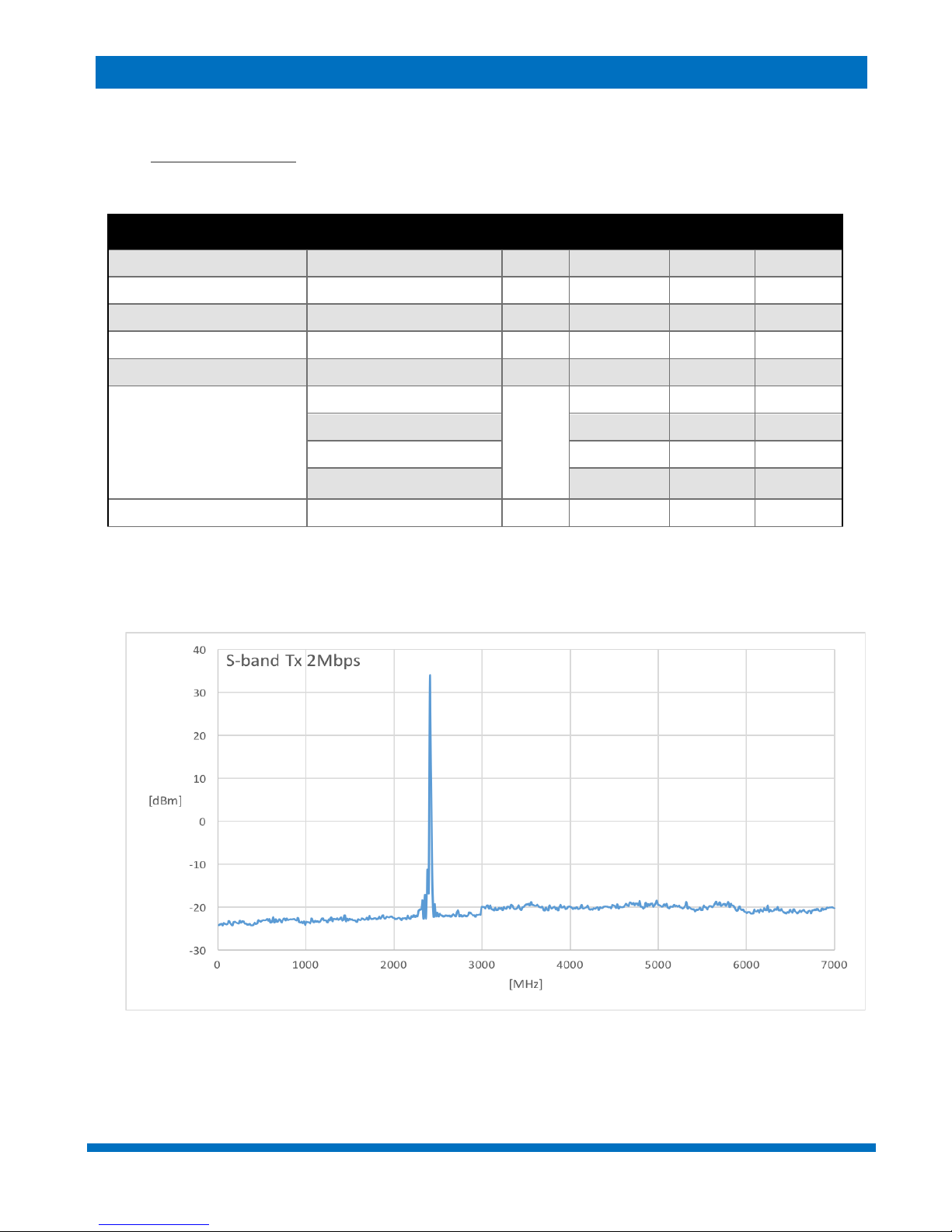
7.1 Transceiver S-Band
Figure 4 - Central frequency 2411MHz - 2Mbps - full span
Parameter
Condition
Unit
Min
Typ
Max
Freq. Range
MHz
2400
2480
Output Power
W
2
Channel Distance
MHz
5
Number of Channels
10
Bit Rate
4 different bit rates
kbps
250
2048
High Sensitivity
(0.1% BER)
PER < 1% @250kbps
dBm
-94
PER < 1% @500kbps
-92
PER < 1% @1Mbps
-88
PER < 1% @2Mbps
-86
Input Power
dBm
10
S-BAND / UHF TRANSCEIVER – USER MANUAL
ENDUROSAT
11
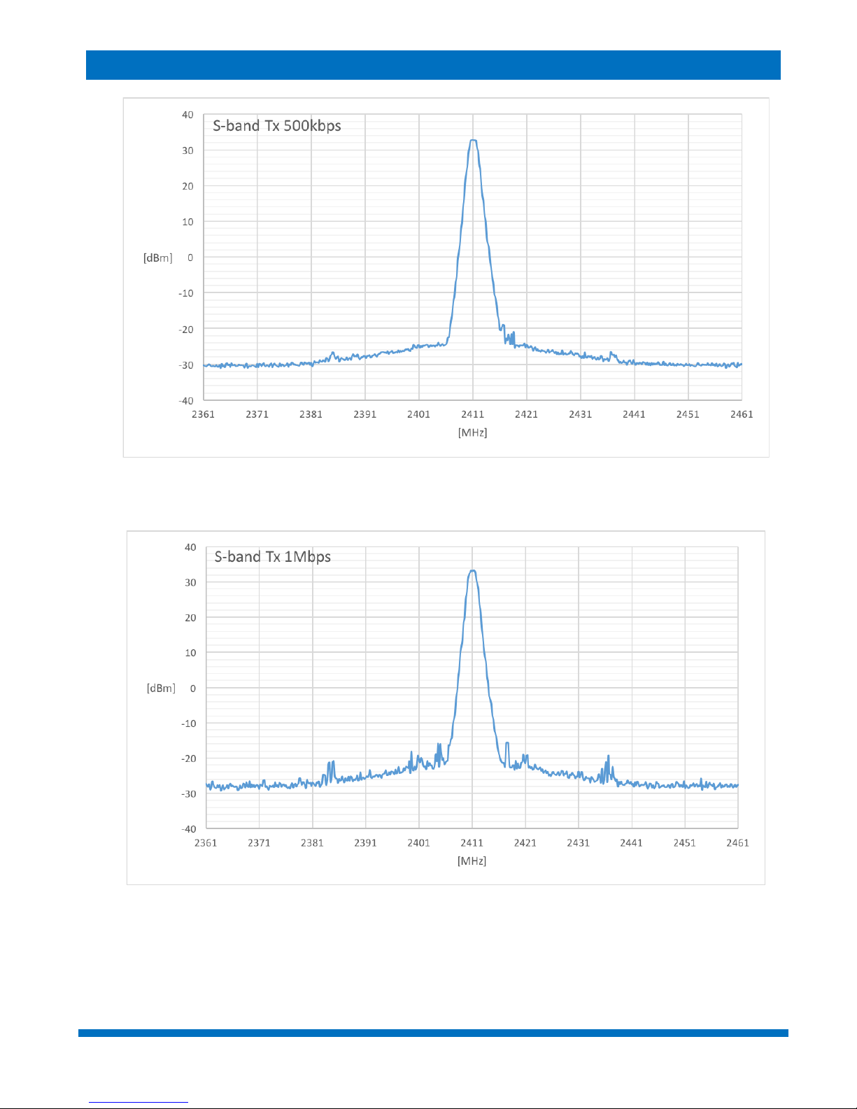
Figure 5 - Central frequency 2411MHz - 500kbps - 100MHz
Figure 6 - - Central frequency 2411MHz - 1Mbps - 100MHz

S-BAND / UHF TRANSCEIVER – USER MANUAL
ENDUROSAT
12
Figure 7 - - Central frequency 2411MHz - 2Mbps - 100MHz
Figure 8 - Central frequency 2411MHz - 500kbps - 20MHz

S-BAND / UHF TRANSCEIVER – USER MANUAL
ENDUROSAT
13
Figure 9 - - Central frequency 2411MHz - 1Mbps - 20MHz
Figure 10 - Central frequency 2411MHz - 2Mbps - 20MHz

S-BAND / UHF TRANSCEIVER – USER MANUAL
ENDUROSAT
14
7.2 Transceiver UHF
Figure 11 - - UHF Transmitter 2000 baud rate - full span
Parameter
Condition
Unit
Min
Typ
Max
Freq. Range
MHz
430
440
Output Power
W
1.5
Channel Distance
kHz
12.5
Number of Channels
255
Serial Port Baud Rate
fixed
bps
9600
Baud Rate In The Air
2 different baud rates
bps
2000
12000
Sensitivity
PER<1% @2000bps
dBm
-121
PER<1% @12000bps
-113
Input Power
dBm
10

S-BAND / UHF TRANSCEIVER – USER MANUAL
ENDUROSAT
15
Figure 12 - - UHF Transmitter 2000 baud rate - 2 MHz
Figure 13 - - UHF Transmitter 12000 baud rate - 2 MHz
S-BAND / UHF TRANSCEIVER – USER MANUAL
ENDUROSAT
16
8 CONNECTOR PINOUT
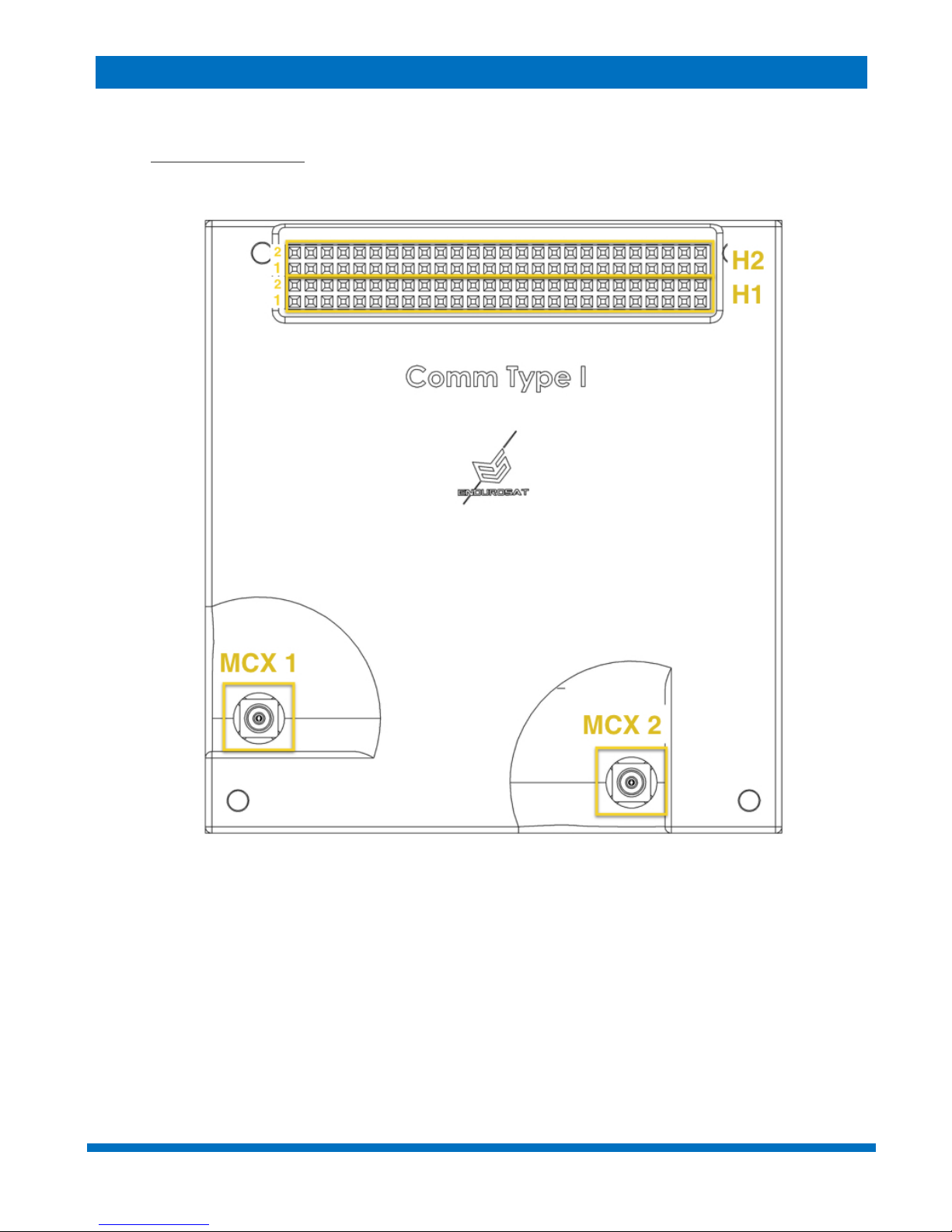
8.1 Connectors Location
Figure 14 - - Connectors Location
MCX 1 -S-Band Antenna Connector
MCX 2 -UHF Antenna Connector
S-BAND / UHF TRANSCEIVER – USER MANUAL
ENDUROSAT
17
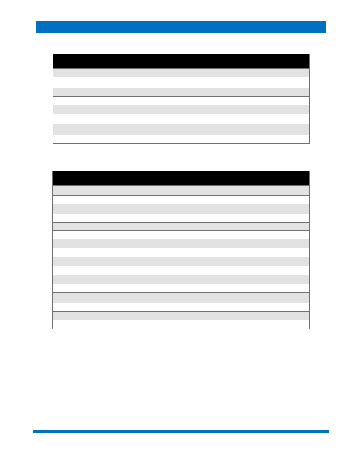
8.2 H1 - Stack Connector
Pin
Mnemonic
Description
H1-19
RXD0
UART RX data – S-band (debug purposes)
H1-20
TXD0
UART TX data – S-band (debug purposes)
H1-33
RXD1
UART RX data – UHF
H1-35
TXD1
UART TX data – UHF
H1-41
SDAO
I2C data pin – UHF (mission specific)
H1-43
SCLO
I2C clock pin – UHF (mission specific)
H1-48
LUP1
Power supply line
H1-51
LUP2
Power supply line
8.3 H2 - Stack Connector
Pin
Mnemonic
Description
H2-5
EN2400
S-band power enable pin
H2-7
EN433
UHF power enable pin
H2-9
MISO_M
General SPI pin
H2-10
MOSI_M
General SPI pin
H2-11
SCK_M
General SPI pin
H2-13
TR
currently not used
H2-15
CS_M
General SPI pin
H2-16
IRQ_M
Events occur on the rising edge of the IRQ_M pin
H2-25
+5V
Power supply
H2-26
+5V
Power supply
H2-27
+3V3
Power supply
H2-28
+3V3
Power supply
H2-29
GND
Power supply
H2-30
GND
Power supply
H2-31
GND
Power supply
H2-32
GND
Power supply
S-BAND / UHF TRANSCEIVER – USER MANUAL
ENDUROSAT
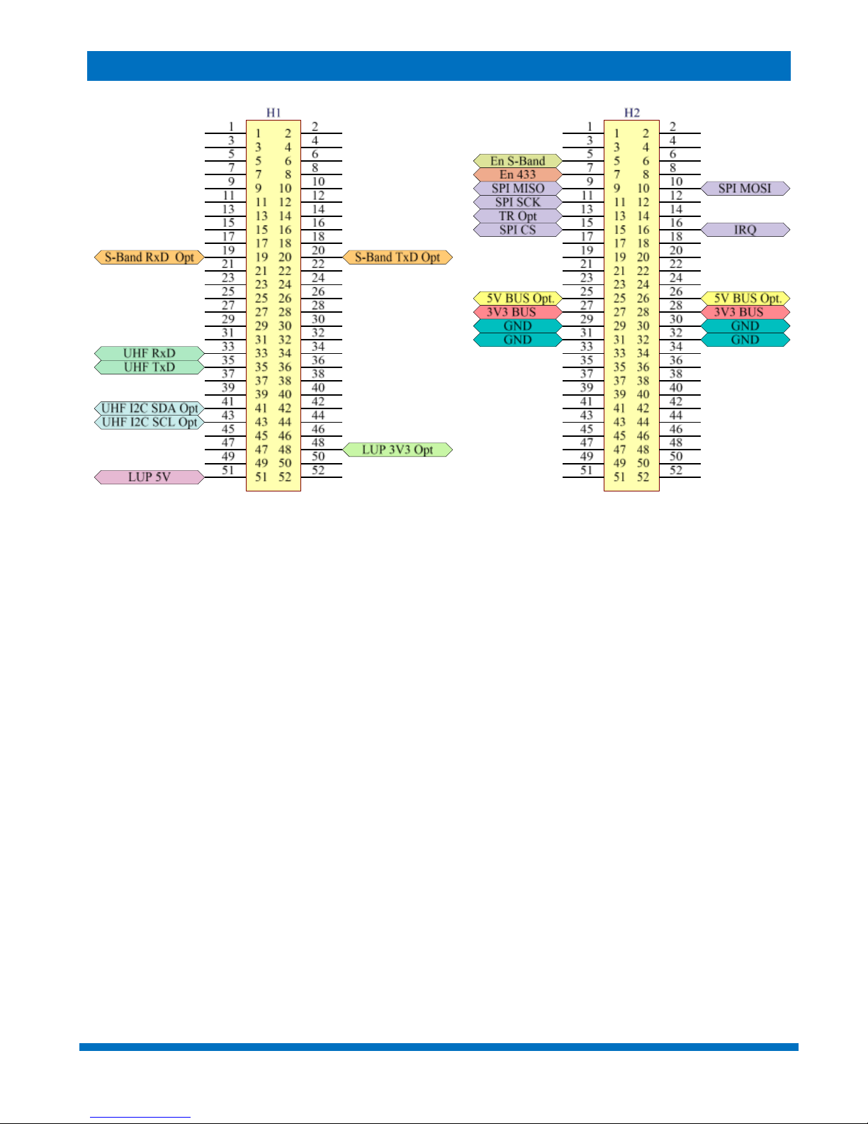
18
Figure 15 - Headers pinout

S-BAND / UHF TRANSCEIVER – USER MANUAL
ENDUROSAT
19
9 MECHANICAL DRAWING
The following pictures show the external dimensions of the S-band / UHF communication module.
STEP files can be provided upon request. All dimensions are in mm.
Figure 16 - Communication module - top view
Figure 17 - - Communication module - side view

S-BAND / UHF TRANSCEIVER – USER MANUAL
ENDUROSAT
20
10 ENVINRONMENTAL AND MECHANICAL TESTING
A full campaign of tests at qualification level was performed on the qualification engineering model.
Qualification tests level and duration follow the ESA standard ECSS-E-ST-10-03C and GEVS: GSFC-
STD-7000A. Test performed:
• Thermal Cycling
• Thermal Vacuum
• Random Vibration
• Sine Vibration
• Shock Test
Test report can be provided upon request.
11 MATERIALS AND PROCESSES
• Surface mount technology component placement
• Standard: IPC-A-610E Class 3
• Aluminum 6061 T651 shell
• Visually inspected
• X-ray checked
• Functionally verified
12 HANDLING AND STORAGE
Particular attention shall be paid to the avoidance of damage of the Communication module during
handling, storage and preservation. The handling of the communication module should be performed
in compliance with the following instructions:
• Handle using PVC gloves, latex, cotton (lint free) or nylon.
• The environment where subsystem will be handled shall meet the requirements for a class
environment 100,000, free of contaminants such dust, oil, grease, fumes and smoke from
any source.
• Store in such a manner as to preclude stress and prevent damage
• To prevent the deterioration, the module shall be stored through the maintenance and control
of environments, i.e. the temperature and humidity levels shall be maintained in the proper
ranges:
o Ideal storage temperature range: 15ºC to 27ºC
o Ideal storage humidity range: 30% to 60% relative humidity (RH)
Table of contents


