ENEL UP2020 Lite User manual

GLOBAL STANDARD
Page 1 of 61
Remote Terminal Unit for MV/LV substation –UP2020 Lite
GSTR002
Rev. 02
30/09/2019
1
Remote Terminal Unit for MV/LV substation –UP2020 Lite
2
3
This document describes the UP2020 Lite equipment, the Remote Terminal Unit for
4
telecontrol and supervision of Medium Voltage distribution network integrating an IEC 61850
5
Client; it provides functional and construction requirements for the provision.
6
7
8
9
This document isintellectual property of Enel Spa; reproduction or distribution of its contents in any way or by anymeans whatsoever
10
is subject to the prior approval of the above mentioned company which will safeguard its rights under the civil and penal codes.
11
It is for internal Use. Each Country can provide a translation in local language but the official reference document is this GS English
12
version.
13
14
Revision
Data
List of modifications
00
28.05.2018
First draft
01
06.06.2018
First approved draft for large area implementation in Italy
02
30.09.2019
Second approved editon.Includesthe outcomes of the DtV –Design to Value –methodology
15
16
Countries’ I&N
Elaborated by
Collaborations by
Verified by
Approved by
Argentina
-
-
-
Carlos Espinoza
Brasil
-
-
-
Darcio De Souza
Dias
Chile
-
-
-
Daniel Gonzalez
Colombia
-
-
-
Juan Gomez
Iberia
José Luis Calero
Juan Miguel
Gonzalez Provost
-
-
Maria Avery
Italy
Stefano Riva
Carla Marino
Domenico
Demuro
Gianluca
Sapienza
Gianluca
Sapienza
Peru
-
-
-
Robert Sanchez
Romania
-
-
-
Vasilica Obrejan
Elaborated by
Collaborations by
Verified by
Approved by
Global I&N –NTI
Giorgio Scrosati
Michele Negro
Giorgio Scrosati
Fabio Giammanco

INDEX
17
1ACRONYMS ......................................................................................................................................5
18
2APPLICABLE LAWS, REFERENCE STANDARDS AND ENEL STANDARDS ..........ERRORE. IL
19
SEGNALIBRO NON È DEFINITO.
20
2.1 For all countries...............................................................................................................................................6
21
2.2 For EU...............................................................................................................................................................7
22
2.3 For Iberia..........................................................................................................................................................7
23
2.4 , Enel Global Standards quoted in the document....................................Errore. Il segnalibro non è definito.
24
3INTRODUCTION.....................................................ERRORE. IL SEGNALIBRO NON È DEFINITO.
25
4LIST OF COMPONENTS, PRODUCT FAMILY OR SOLUTIONS....................................................8
26
4.1 Components of the Remote terminal Unit for Secondary substation in the configurations available.....8
27
4.2 Enel Product family codes of the components.............................................................................................8
28
4.3 List of components, product family and solutions to which the Global Standard applies...........Errore. Il
29
segnalibro non è definito.
30
5TECHNICAL CHARACTERISTICS OF THE UE2020 LITE............................................................10
31
5.1 Construction characteristics........................................................................................................................12
32
5.2 UE Functions .................................................................................................................................................12
33
5.2.1 Chronological recording of fault current flows.............................................................................................12
34
5.2.2 Measurements............................................................................................................................................13
35
5.2.3 Faulty branch selection...............................................................................................................................13
36
5.2.4 Busbar voltage presence calculation (RVS)................................................................................................13
37
5.2.5 UP2020 I/O interface module function........................................................................................................13
38
5.2.6 Auxiliary functions.......................................................................................................................................13
39
5.2.6.1. Communication...........................................................................................................................................13
40
5.2.6.2. Diagnostics.................................................................................................................................................14
41
5.2.6.3. Date/time clock function..............................................................................................................................14
42
5.2.7 Configuration and Programming.................................................................................................................14
43
5.2.7.1. Configuration uploading..............................................................................................................................14
44
5.2.7.2. Downloading of the firmware ......................................................................................................................15
45
5.2.8 Functionalities based on MQTT protocol ....................................................................................................15
46
5.2.8.1. DBR Automation.........................................................................................................................................15
47
5.2.8.2. Galileo Functionality....................................................................................................................................15
48
5.3 UE technical details.......................................................................................................................................18
49
5.3.1 Cables.........................................................................................................................................................19
50
5.3.2 Connectors .................................................................................................................................................19
51
5.3.3 Input terminals ............................................................................................................................................20
52
5.3.4 Power supply..............................................................................................................................................20
53
5.3.5 Remote controls..........................................................................................................................................20
54
5.3.6 Remote signals...........................................................................................................................................21
55
5.3.7 Measurements............................................................................................................................................21
56
5.3.8 Data buffering mode ...................................................................................................................................22
57
5.3.9 Diagnostics.................................................................................................................................................22
58
5.3.10 Features of the date-time clock...................................................................................................................23
59
6TECHNICAL CHARACTERISTICS OF THE PSBC........................................................................24
60
6.1 PSBC construction characteristics..............................................................................................................24
61
6.2 PSBC electrical characteristics....................................................................................................................24
62
6.3 Control of the mains, power supply and battery voltages.........................................................................26
63
6.3.1 Test of the battery efficiency.......................................................................................................................26
64
6.3.2 Specification of the DCE power supply section...........................................................................................27
65
6.3.3 Configuration, signaling and protection devices..........................................................................................28
66
7COMMUNICATION PROTOCOLS AND TRANSMISSION EQUIPMENT......................................30
67
7.1 IEC 60870-5-101 protocol..............................................................................................................................30
68
7.2 IEC 60870-5-104 protocol..............................................................................................................................31
69
7.3 Transmission equipment (DCE) ...................................................................................................................31
70
7.3.1 GSM/GPRS modem....................................................................................................................................32
71
7.3.1.1. Physical interface to an external modem....................................................................................................32
72
7.3.1.2. Data interchange with the modem ..............................................................................................................32
73
7.3.1.3. Modem management..................................................................................................................................32
74

GLOBAL STANDARD
Page 3 of 61
Remote Terminal Unit for MV/LV substation –UP2020 Lite
GSTR002
Rev. 02
30/09/2019
8TESTING AND INSPECTION..........................................................................................................34
75
8.1 Overview of the tests required for the RTU and its components..............................................................34
76
8.2 Type tests.......................................................................................................................................................34
77
8.2.1 Visual inspection.........................................................................................................................................34
78
8.2.2 Tests of insulation and dielectric strength...................................................................................................34
79
8.2.3 Check of all of the functionalities.................................................................................................................35
80
8.2.3.1. UE...............................................................................................................................................................35
81
8.2.3.2. PSBC..........................................................................................................................................................35
82
8.2.4 Stability check (PSBC only) ........................................................................................................................36
83
8.2.5 Electromagnetic interference immunity test................................................................................................36
84
8.2.5.1. UE...............................................................................................................................................................37
85
8.2.5.2. PSBC..........................................................................................................................................................37
86
8.2.6 Thermal behavior test (PSBC only).............................................................................................................37
87
8.2.7 Climatic Tests .............................................................................................................................................38
88
8.2.8 Mechanical tests.........................................................................................................................................38
89
8.3 Acceptance tests...........................................................................................................................................40
90
8.3.1 Preliminary checks......................................................................................................................................40
91
8.3.2 Functional check.........................................................................................................................................40
92
8.3.3 Automatic Testing System (ATS)................................................................................................................41
93
9SUPPLY REQUIREMENTS.............................................................................................................43
94
9.1 Voltage selector switch in the PSBC ...........................................................................................................43
95
9.2 TCA documents and Manuals ......................................................................................................................43
96
9.2.1 TCA documents..........................................................................................................................................43
97
9.2.2 Manuals ......................................................................................................................................................43
98
9.2.3 Safety warnings on Plate............................................................................................................................43
99
10 AMBIENT OPERATING CONDITIONS...........................................................................................43
100
11 ELECTROMAGNETIC COMPATIBILITY........................................................................................44
101
11.1 Immunity requirements.................................................................................................................................44
102
11.2 Emission limits ..............................................................................................................................................44
103
12 SAFETY REQUIREMENTS.............................................................................................................44
104
13 SOFTWARE.....................................................................................................................................44
105
13.1 Remote connection with the Center.............................................................................................................44
106
13.2 Remote programming and configuration ....................................................................................................44
107
13.3 Local programming and configuration........................................................................................................44
108
14 GENERAL PRESCRIPTIONS.........................................................................................................46
109
14.1 Reliability........................................................................................................................................................46
110
14.1.1 Normative references..................................................................................................................................46
111
14.1.2 Formulation of the reliability requirements..................................................................................................46
112
14.1.3 Verification tests of compliance with the declared failure rates...................................................................46
113
14.2 Electronic Boards and components prescriptions.....................................................................................46
114
14.3 Project technical documentation .................................................................................................................47
115
14.4 Spare parts.....................................................................................................................................................47
116
14.5 Equipment documentation ...........................................................................................................................47
117
15 OPTIONAL SENSOR: NETTUNO...................................................................................................48
118
15.1 Power supply.................................................................................................................................................48
119
15.2 Operating........................................................................................................................................................48
120

GLOBAL STANDARD
Page 4 of 61
Remote Terminal Unit for MV/LV substation –UP2020 Lite
GSTR002
Rev. 02
30/09/2019
15.3 Connection.....................................................................................................................................................49
121
15.4 Features..........................................................................................................................................................49
122
15.5 Installation......................................................................................................................................................50
123
15.6 Reliability........................................................................................................................................................50
124
15.7 Manual and accompanying documentation ................................................................................................50
125
15.8 Plate Data.......................................................................................................................................................50
126
16 APPENDIX.......................................................................................................................................51
127
17 CYBERSECURITY PRESCRIPTIONS............................................................................................61
128
129

GLOBAL STANDARD
Page 5 of 61
Remote Terminal Unit for MV/LV substation –UP2020 Lite
GSTR002
Rev. 02
30/09/2019
1 ACRONYMS
130
DCE
Data Circuit-terminating Equipment
DCS
Digital Cellular Service
DTE
Data Terminal Equipment
DFPI
Directional Fault Passage Indicator
FPI
Fault Passage Indicator
GS
SD
Enel Global Standard
Switch Disconnector
SG
Switchgear
PSBC
Power supply/ battery charger of the RTU
PSTN
Public Switched Telephone Network
RGDAT
Enel standardized Directional fault passage and voltage loss indicator
RGDM
Advanced Fault Passage indicator with measuring acquisition
BVI
mains failure, Busbar Voltage Indicator
RC
Remote Control
RTU
Remote Terminal Unit
TM
Tele-Metering/Tele-Measurement
RS
Remote Signaling
TCA
Technical Conformity Assessment
TR
Transformer
UE
Processing Unit Device of the RTU
UP
Enel standardized Remote Terminal Unit for telecontrol and supervision of
Medium Voltage distribution network
131

GLOBAL STANDARD
Page 6 of 61
Remote Terminal Unit for MV/LV substation –UP2020 Lite
GSTR002
Rev. 02
30/09/2019
2 NORMATIVE REFERENCES AND BIBLIOGRAPHY
132
All the references in this GS are intended in the last revision or amendment.
133
2.1 For all countries
134
IEC 60068-2-1
Environmental testing - Part 2-1: Tests - Test A: Cold
IEC 60068-2-14
Environmental testing - Part 2-14: Tests - Test N: Change of temperature
IEC 60068-2-2
Environmental testing - Part 2-2: Tests - Test B: Dry heat
IEC 60068-2-6
Environmental testing - Part 2-6: Tests - Test Fc: Vibration (sinusoidal)
IEC 60068-2-64
Environmental testing - Part 2-64: Tests - Test Fh: Vibration, broadband random and guidance
IEC 60068-2-78
Environmental testing - Part 2-78: Tests - Test Cab: Damp heat, steady state
IEC 60255-27
Measuring relays and protection equipment - Part 27: Product safety requirements
IEC 61000-4-12
Electromagnetic compatibility (EMC) - Part 4-12: Testing and measurement techniques - Ring wave
immunity test
IEC 61000-4-16
Electromagnetic compatibility (EMC) - Part 4-16: Testing and measurement techniques - Test for
immunity to conducted, common mode disturbances in the frequency range 0 Hz to 150 kHz
IEC 61000-4-18
Electromagnetic compatibility (EMC) - Part 4-18: Testing and measurement techniques - Damped
oscillatory wave immunity test
IEC 61000-4-2
Electromagnetic compatibility (EMC) - Part 4-2: Testing and measurement techniques - Electrostatic
discharge immunity test
IEC 61000-4-29
Electromagnetic compatibility (EMC) - Part 4-29: Testing and measurement techniques - Voltage dips,
short interruptions and voltage variations on d.c. input power port immunity tests
IEC 61000-4-3
Electromagnetic compatibility (EMC) - Part 4-3: Testing and measurement techniques - Radiated,
radio-frequency, electromagnetic field immunity test
IEC 61000-4-3
Interpretation sheet 1 - Electromagnetic compatibility (EMC) - Part 4-3: Testing and measurement
techniques - Radiated, radio-frequency, electromagnetic field immunity test
IEC 61000-4-4
Electromagnetic compatibility (EMC) - Part 4-4: Testing and measurement techniques - Electrical fast
transient/burst immunity test
IEC 61000-4-5
Electromagnetic compatibility (EMC) - Part 4-5: Testing and measurement techniques - Surge
immunity test
IEC 61000-4-6
Electromagnetic compatibility (EMC) - Part 4-6: Testing and measurement techniques - Immunity to
conducted disturbances, induced by radio-frequency fields
IEC 61000-4-8
Electromagnetic compatibility (EMC) - Part 4-8: Testing and measurement techniques - Power
frequency magnetic field immunity test
IEC 60332-3-10
Tests on electric and optical fibre cables under fire conditions
IEC 60870-5-101
Telecontrol equipment and systems - Part 5-101: Transmission protocols - Companion standard for
basic telecontrol tasks
IEC 60870-5-104
Telecontrol equipment and systems - Part 5-104: Transmission protocols - Network access for IEC
60870-5-101 using standard transport profiles
IEC 60529
Degrees of protection provided by enclosures (IP code)
IEC 61000-6-4:
Electro-magnetic compatibility (EMC) - Part 6-4: Generic standards - Emission standard for industrial
environments;
CISPR 32
Electromagnetic compatibility of multimedia equipment - Emission requirements

GLOBAL STANDARD
Page 7 of 61
Remote Terminal Unit for MV/LV substation –UP2020 Lite
GSTR002
Rev. 02
30/09/2019
CISPR 11
Industrial, scientific, and medical (ISM) equipment - Radio frequency disturbance characteristics -
Limits and methods of measurement
GSTR002
Remote Terminal Unit for MV/LV substation –UP2020 Lite
GSTR001/1
Remote Terminal Unit for secondary substations (UP)
GSTR001/2
UP - Box for indoor installations
GSTR001/3
UP - Box for Outdoor installations
GSCG002
Technical Conformity Asessment
GSCB001
12V Accumalators for remote control secondary substations
GSTP001
RGDAT-A70
GSTP011
RGDM Global Standard
2.2 For EU countries
135
EN 50160
Voltage characteristics of electricity supplied by public distribution systems
2.3 For Iberia
136
R.D. 337/2014
Por el que se aprueban el Reglamento sobre condiciones técnicas y garantías de
seguridad en instalaciones eléctricas de alta tensión y sus Instrucciones Técnicas
Complementarias ITC-RAT 01 a 23.
137

GLOBAL STANDARD
Page 8 of 61
Remote Terminal Unit for MV/LV substation –UP2020 Lite
GSTR002
Rev. 02
30/09/2019
3 LIST OF COMPONENTS, PRODUCT FAMILY AND SOLUTIONS TO WICH THE GS APPLIES
138
3.1 Components of the Remote terminal Unit for Secondary substation in the configurations
139
available
140
The UP is available in different configurations, applicable to indoor and outdoor installations.
141
It consists of:
142
a rack mounted processing unit device, namely UE
143
a rack mounted power supply/battery charger, namely PSBC
144
the cabinet, that can be suitable for indoor or outdoor installation
145
The UE and the PSBC are both suitable for installation to ether indoor or outdoor cabinets and their
146
characteristics are described in this specification.
147
The containers can have different shapes according to their applications. Their characteristics are
148
described in the following Global Standards:
149
UP Cabinet for Indoor installations: GSTR001/2
150
UP Cabinet for Outdoor installations: GSTR001/3
151
3.2 Enel Product family codes of the components
152
Global Product
Family Code
Description
Reference Global Standard
Included in the
Global Product
family code
WM-UP2020 L8
Complete Kit
Complete UP2020 Lite kit for Indoor application,
mounted in the Wall-mounted indoor cabinet container
equipped with UE2020 L8
GSTR002
GSTR001/2
PSBC
UE2020 L8
WM-UP
WM-UP2020 L16
Complete Kit
Complete UP2020 Lite kit for Indoor application,
mounted in the Wall-mounted indoor cabinet container
equipped with UE2020 L16
GSTR002
GSTR001/2
PSBC
UE2020 L16
WM-UP
OS-UP2020Lite
Complete Kit
Complete UP2020 Lite kit for Outdoor application,
mounted in the Outdoor cabinet container equipped with
UE2020 L8
GSTR002
GSTR001/3
PSBC
UE2020 L8
OS-UP
CM-UP2020Lite
Complete Kit
Complete UP kit for Indoor application, mounted Ceiling
mounted mounted in the Ceiling-mounted indoor cabinet
container equipped with UE2020 L8
GSTR002
GSTR001/3
PSBC
UE2020 L8
CM-UP
PSBC
Power supply and battery charger
GSTR001/1
UE2020 L8
Processing Unit Device capable to telecontrol for 8
switchgears
GSTR002
UE2020 L16
Processing Unit Device capable to telecontrol for 16
switchgears
GSTR002
CM-UP
Ceiling-mounted indoor cabinet container for Remote
Terminal Unit
GSTR001/2
WM-UP
Wall-mounted indoor cabinet container for indoor
Remote Terminal Unit
GSTR001/2
OS-UP
Outdoor cabinet container for pole-mounted Remote
Terminal Unit - standard version
GSTR001/3

GLOBAL STANDARD
Page 9 of 61
Remote Terminal Unit for MV/LV substation –UP2020 Lite
GSTR002
Rev. 02
30/09/2019
OXL-UP
Outdoor cabinet container for pole-mounted Remote
Terminal Unit - Extra-large version
GSTR001/3
Spare part: connection cable to the switch
Spare part: connection cable to the RGDAT
Table 1 –UP2020 Lite Global Product Family codes. The merchandise group for these items is FTTE0501
1
153
154
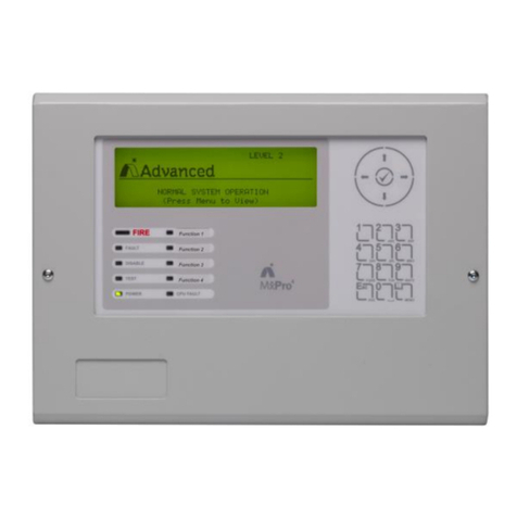
Figure 1 –PSBC
Figure 2 –UE2020 L8
Figure 3 –UE2020 L16
155
The UE and the PSBC devices are equipped with the accessories provided in Table 2:
156
157
Accessories
Product
family
code
Device
Description
Included in
the supply
Cable connecting
UE to PSBC
UE2020
L8/UE2020 L16
The cable is composed of 11 conductors, with
section 1,5mm2, terminating with two 12 pin
loating connectors (see Figure 9).
Yes
RS232 cable for
DCE connection
UE2020
L8/UE2020 L16
It is a DB9 Male/DB25 Female Modem Cable of
length equal to1.5m.
Yes
Mains three pole
plug
PSBC
It is a three-pole plug (type IEC C13 according to
IEC 60320 standard) for the termination of the
cable (not included) of the AC power supply
Yes
Table 2 - Accessories of the UE and PSBC devices
158
159
1
Please use this merchandise group when new local material codes are issued on the TAM system.

GLOBAL STANDARD
Page 10 of 61
Remote Terminal Unit for MV/LV substation –UP2020 Lite
GSTR002
Rev. 02
30/09/2019
4 INTRODUCTION
160
The UP2020 Lite equipment is an enhanced version of the RTU, consisting of all the functionalities and
161
hardware requirements of UP 2015 Global RTU, but integrated with furter software functionalities, detailed
162
in this specification document.
163
For this reason the UP2020 Lite specification (GSTR002) is based on the UP2015 specification
164
(GSTR001/1, rev.1) and most of its technical attachments continues to apply to UP2020 Lite.
165
Enel standardized MV remote control solution include a Remote Terminal Unit (RTU) and, optionally, as
166
many fault detectors as the Line Out switches.
167
The components and elements of a MV/LV substation that can be remote controlled include MV and LV
168
switch-disconnectors and circuit breakers. The Global Standard GSTR002 describe the standardized
169
Remote Terminal Unit (RTU), also called UP, which can be used to remote control MV/LV substations, or
170
to remote control pole mounted motorized switches. The UP is also the devices responsible to execute
171
the self-healing distributed automation, when coupled with standardized fault detectors.
172
The central Remote Control System (Center, in the remainder) of the medium voltage distribution network
173
is composed of:
174
a Central Unit;
175
a Front-end for communication with peripheral devices;
176
Working Stations;
177
etc.
178
The central unit is intended to perform the following functions:
179
validation and transmission of the commands given by the operator to the Remote Terminal Units
180
(RTU);
181
acquisition, processing, and storage of data coming from the RTUs;
182
selection of the faulty branches;
183
configuration and remote diagnostics of the RTUs;
184
Synchronization of the clocks of the RTUs.
185
This document describes the functions of the RTU devoted to medium voltage distribution network, and
186
provides, nonetheless, the construction requirements for the provision.
187
The Center is capable to use all of the communication systems available on the market (public switched
188
telephone networks, mobile networks, etc.), or those which can be implemented ad hoc (dedicated radio
189
networks), which ensure messages transit times compatible with the System requirements.
190
The RTUs are expected to carry out the following functions:
191
To communicate with the central system and ensure the forwarding to the field device of the
192
remote controls received by the Center. A field device can be:
193
oMedium Voltage Switch Disconnectors (SD), located in Secondary Substations or pole
194
mounted
195
oMedium Voltage Circuit-Breakers located in Secondary Substations or (SSCB) or pole
196
mounted
197
oReclosers
198
oLow Voltage motor-driven Circuit Breakers (LVCB) in the secondary substations
199
(switchgears in their general acceptation);
200
To detect the status of the switchgears and the diagnostics of each RTU, and make them available
201
to the Center;
202
To detect the fault signal from the fault passage indicators or protections (RGDAT/RGDM) that
203
are installed in correspondence of the switches to be monitored, and subsequently store them with
204
the date/time of occurrence, in order to make them available to the Central Unit;
205
To implement automatic procedures for the selection of the faulty branches;
206
To record field measurements (indoor temperature of the substation, currents, etc.), and make
207
them available to the Center.
208

GLOBAL STANDARD
Page 11 of 61
Remote Terminal Unit for MV/LV substation –UP2020 Lite
GSTR002
Rev. 02
30/09/2019
The RTUs can also be used as a part of MV/MV switching substations, where they remotely control the
209
circuit breakers, and record the signals and measurements from the related protection and control panels.
210

GLOBAL STANDARD
Page 12 of 61
Remote Terminal Unit for MV/LV substation –UP2020 Lite
GSTR002
Rev. 02
30/09/2019
5 TECHNICAL CHARACTERISTICS OF THE UE2020 LITE
211
5.1 Construction characteristics
212
The UE functional blocks must be designed as a chassis suitable for mounting onto a 19” normalized
213
frame rack. The size of the chassis must be the following:
214
•a height equal to 4U, as to the UE2020 L8 version;
215
•a height equal to 7U, as to the UE2020 L16 version;
216
•a depth equal at most to 25 cm for both the UE2020 L8 and UE2020 L16 versions, according to the
217
dimensions described in Figure 4.
218
The UE2020 L8 and UE2020 L16 devices are made of steel or an equivalent material in terms of
219
electromagnetic compatibility and rigidity of the structure. They are supported only by the screws of the
220
front panel. The UE must ensure at least an IP30 degree of protection (EN 60529).
221
Front panels must be provided with a 6MA grounding bolt.
222
5.2 UE Functions
223
The UE has to allow the execution of configurable actuation time commands, in order to remote control
224
different types of existing switchgears (switch disconnectors, LV circuit breakers, reclosers, and MV circuit-
225
breakers).
226
For each switchgear, the UE must record double permanent signals for its status (open and closed).
227
In the case of switched line\GSM channel communication between the UE and the central system:
228
The UE must be capable to independently establish the connection with the Center (spontaneous
229
calls), as a consequence of specific events previously configured or when analog measurements
230
exceed preconfigured thresholds.
231
The Center must be capable to execute the spontaneous call by means of a remote command;
232
The UE must manage a phone list consisting of three numbers to call in case of spontaneous call
233
event.
234
Communication between the Center and the UE can also be permanent:
235
on dedicated line, by using EC 60870-5-101 protocol;
236
on IP network using IEC 60870-5-104 protocol and either the Ethernet port or the serial port
237
(provided on the front).
238
The UE has to run the following monitoring functions related to the MV network operation:
239
chronological recording of any event: this information must be accessible from local and remote
240
access;
241
measurements execution;
242
faulty branch selection;
243
auxiliary functions.
244
5.2.1 Chronological recording of fault current flows
245
The UE has to chronologically record all the events with a precision of one thousandth of a second .
246
Chronological recording of fault current flows must be made available to the Central Unit, to be used:
247
in real time, when permanent faults occur, for the selection of the faulty branch;
248
in deferred time, to facilitate maintenance operations.
249

GLOBAL STANDARD
Page 13 of 61
Remote Terminal Unit for MV/LV substation –UP2020 Lite
GSTR002
Rev. 02
30/09/2019
A special requirement regarding the logging function for ENDESA is provided as an external annex “RTU
250
REMOTE ACCESS WITH VOYAGER SYSTEM”.
251
252
5.2.2 Measurements
253
The UE is equipped with analogue inputs for the measurement of significant parameters of the secondary
254
substation. A dedicated input for a PT100 sensing element must be provided in order to measure the
255
ambient temperature.
256
5.2.3 Faulty branch selection
257
The UE must implement a series of local automatisms. According to the status of given inputs, these
258
automatisms generate the opening and/or closing commands of the switchgears aimed at searching the
259
faulty branch.
260
Upon the occurrence of well-defined events, or specific status transitions, the UE must be able to generate
261
spontaneous calls toward the Center.
262
From the Center it has to be possible to individually disable each function related to spontaneous call
263
and/or exclusion of the automatisms, by means of remote commands.
264
The comprehensive description of all the automatisms to be implemented in the UE is included in a specific
265
confidential technical specification. The technical specification describing the Automatisms will be
266
delivered in its complete version only after the contract is awarded.
267
During the tender, only an extract is provided, being sufficient for a technical/economic assessment.
268
5.2.4 Busbar voltage presence calculation (RVS)
269
The UE must manage the presence of the busbar voltage for sending the signal to digital devices.
270
The calculation of this signal must be performed with these modes:
271
if the RVS signal in the available remote signals is configured, the busbar voltage presence signal
272
will be active when the RVS signal is also active
273
if the RVS signal in the available remote signals is not configured, the bus voltage presence signal
274
will be active when the "Mains failure / BVI" signal will not be active
275
5.2.5 UP2020 I/O interface module function
276
The UE must be able to behave as an input/output interface module for the UP2020.
277
The communication interface will take place via Ethernet port with IEC 60870-5-104 communication
278
protocol.
279
It must be possible through the software to configure the following exclusive mode of operation.
280
The hardware configuration of the switchgears will take place by protocol through file transfers with json
281
and binary files.
282
The automation cycles for the selection of the faulty branch must be performed locally.
283
5.2.6 Auxiliary functions
284
5.2.6.1. Communication
285
The Center has to be capable to communicate with the UE by means of all the following media:
286
Switched Telephone Network (PSTN);
287
4-wire dedicated analog channels (4W Leased);
288
GSM and DCS 1800 mobile network;
289
IP networks;
290

GLOBAL STANDARD
Page 14 of 61
Remote Terminal Unit for MV/LV substation –UP2020 Lite
GSTR002
Rev. 02
30/09/2019
Satellite network;
291
Radio network.
292
The device Hardware and software architecture must be flexible and easily allow the interchangeability
293
among the above mentioned communication systems, as explained in the remainder.
294
5.2.6.2. Diagnostics
295
The UE must include diagnostic functions of control, management, and local and remote reporting of
296
anomalies in the operation of its functional parts.
297
5.2.6.3. Date/time clock function
298
The UE must be equipped with an internal low drift and high resolution date/time clock.
299
All fault current detection or other system events must be stored in the internal buffer with a date/time
300
stamp, according to a timing resolution of one thousanth of a second.
301
302
5.2.7 Configuration and Programming
303
It has to be possible to fully configure and program the UE either:
304
locally, by means of a PC (not included in the supply), connected to the USB port
305
remotely, via the DCE or the Ethernet network.
306
The UE configuration, either locally or remotely, is described into Annex 1: “Remote Terminal Unit
307
Configuration and Application Program Interface specifications”.
308
Annex 2: UE configuration parameters contains the overall list of the UE configuration parameters.
309
Annex 3: Remote Terminal Unit Protocols Specifications, describes UP, the Remote Terminal Unit for
310
telecontrol and supervision of Medium Voltage distribution network; it provides functional and construction
311
requirements for the provision .
312
Annex 4: provides the list of the Information Object Addresses (IOAs), compliant with the IEC 60850-5-
313
101/104 protocols, related to the signals, measurements, controls, statuses of the automatisms stored into
314
the UE database. Also a mapping between IEC 60850-5-101/104 and IEC 61850 protocols is provided.
315
316
The addition or modification of any record in the UE database must be possible by updating the device
317
application firmware and reconfiguring it from the Center (i.e. local reconfiguration must not be required).
318
All of the user application software provided must meet the following requirements:
319
Compatibility with OS Windows 7 and OS Windows 10 64 bit;
320
Availability of “silent-mode” installation and update through Software Delivery.
321
A mobile application (ANDROID 4.2) must be also provided, useful to either configure the UE or update
322
the firmware locally, by means of the UE USB port. In order to facilitate the user in the configuration via
323
mobile, the application will be provided with a set of standard configurations.
324
All the interactions (configuration, visualization, firmware download and upload) between the software and
325
the UE on the Ethernet port, must be performed encapsulated in secure protocol (latest version possible
326
of SSH), and file transmission must be performed using SCP.
327
328
5.2.7.1. Configuration uploading
329
The changing of any parameter must be made starting from the configuration setting which is in the UE in
330
that moment, in order to avoid the risk of operating on outdated data.
331

GLOBAL STANDARD
Page 15 of 61
Remote Terminal Unit for MV/LV substation –UP2020 Lite
GSTR002
Rev. 02
30/09/2019
As a consequence, at the beginning of each connection with the UE, the existing configuration must be
332
uploaded, before proceeding with any local or remote configuration of the RTU.
333
5.2.7.2. Downloading of the firmware
334
It must be possible to update locally the firmware of either the UE or the PSBC to the latest version (local
335
downloading), through the same software used also for the configuration.
336
Nonetheless, it has also to be possible the remote download of the firmware for one or more UE
337
(management of lists of devices). This operation may be executed either by the Center, by means of the
338
same communication devices normally used for the remote control, or from a standard PC with a modem
339
or LAN. For this purpose, a suitable software module must be provided, to be installed on a PC.
340
341
5.2.8 Functionalities based on MQTT protocol
342
UP2020 Lite must implement an MQTT Client and an MQTT Broker services. These services will be used
343
to realize a peer-to-peer automation named “DBR”, and for publishing information (statuses and measures)
344
from IoT sensors acquired by TCP ModBus.
345
While utilizing an istance of MQTT Client functionality, it will be necessary to configure at least the following
346
parameters:
347
oBroker IP Address (MQTT Server where to publish messages)
348
oMQTT or MQTT over SSL mode
349
oMQTT TCP Port to be addresses (Default MQTT = 1883, Default MQTT over SSL = 8883)
350
351
352
5.2.8.1. DBR Automation
353
UP2020 Lite must implement a new automation based on the exchange of communication between RTUs.
354
The principle of this automation is described in the attachment “Automazione DBR - DSR per UP”.
355
Any UP participating to DBR is configured with at least the IP ADDRESS of the next UP (from the
356
topological point of view) installed on the MV network, and the IP ADDRESS of the UP installed on the
357
border of the feeder. DBR allows, thanks to the communication between UPs to manage remote open and
358
remote close of other breakers, managed from remote UP.
359
The automation is fully described by the automatons specification DX1220 ed.11 (latest revision). Some
360
of the states are the trigger condition in order to publish messages to the “Next UP” or to the “Border UP”
361
using MQTT protocol. The procedures reqested at the subscription of a message is described in DX1220
362
ed.11 (latest revision) as well.
363
364
5.2.8.2. Galileo Functionality
365
UP2020 Lite must implement an application gateway for transmission to a specified central system
366
(Server/Broker different from the SCADA system), of information collected by a series of sensors installed
367
in the substation.
368
UP2020 Lite will acquire the information from the sensors by adopting TCP ModBus interface, this interface
369
can be configured via a json file imported into the software.
370
UP2020 Lite will collect such information, store it locally (circular memory with the latest 500 messages),
371
and publish it by adopting a particular topic to the configured MQTT Broker, adopting JSON payloads as
372
exemplified below (real examples of messages recognized and accepted by the MQTT server for the
373
GALILEO application):
374
375
Payload 1 –Electric Measures Example
376

GLOBAL STANDARD
Page 16 of 61
Remote Terminal Unit for MV/LV substation –UP2020 Lite
GSTR002
Rev. 02
30/09/2019
{"TS" : 1516188901179,"TCpu" : 44.01, "V1" : 225.53, "V2" : 225.88, "V3" :
377
226.33, "I1" : 21.40, "I2" : 25.10, "I3" : 11.20, "IN" : 18.40, "U1" : 390.65,
378
"U2" : 392.00, "U3" : 391.22, "PA" : 8670.00, "PR" : 652.00, "Papp" : 13010.00,
379
"F" : 50.00, "PF" : 0.67, "SPF" : 1, "EA" : 11491000.00, "ER" : 204000.00,
380
"SPA" : 0, "SPR" : 0, "PEA" : 11491000.00, "PER" : 204000.00, "NEA" : 1000.00,
381
"NER" : 425000.00, "PAmedia" : 8816.00, "PA1" : 1784.00, "PA2" : 5484.00, "PA3"
382
: 1402.00, "SPA1" : 0, "SPA2" : 0, "SPA3" : 0, "PR1" : 652.00, "PR2" : 0.00,
383
"PR3" : 0.00, "SPR1" : 0, "SPR2" : 0, "SPR3" : 0, "PF1" : 0.37, "PF2" : 0.97,
384
"PF3" : 0.55, "SPF1" : 1, "SPF2" : 1, "SPF3" : 1, "THDV1" : 1.50, "THDV2" :
385
1.30, "THDV3" : 1.40, "THDI1" : 40.00, "THDI2" : 14.10, "THDI3" : 0.00,
386
"Iomopolare" : 0.00, "Q" : 1}
387
388
Payload 2 –Phasors Example
389
{"TS" : 1516188901179, "V1V2" : 240.40, "V2V3" : 239.90, "V3V1" : 239.70,"I1I2"
390
: 215.20, "I2I3" : 32.60, "I3I1" : 112.20,"V1I1" : 18.10, "V2I2" : 0.00, "V3I3"
391
: 0.00, "3ph" : 8.50}
392
393
Payload 3 –I1 Harmonics Example
394
{"TS" : 1516188901179, "HI1_1" : 1000.00, "HI1_3" : 40.00, "HI1_5" : 0.00,
395
"HI1_7" : 0.00, "HI1_9" : 0.00, "HI1_11" : 0.00, "HI1_13" : 0.00, "HI1_15" :
396
0.00, "HI1_17" : 0.00, "HI1_19" : 0.00, "HI1_21" : 0.00, "Q" : 1}
397
398
Payload 4 –I2 Harmonics Example
399
{"TS" : 1516188901179, "HI2_1" : 1000.00, "HI2_3" : 0.00, "HI2_5" : 0.00,
400
"HI2_7" : 0.00, "HI2_9" : 0.00, "HI2_11" : 0.00, "HI2_13" : 0.00, "HI2_15" :
401
0.00, "HI2_17" : 0.00, "HI2_19" : 0.00, "HI2_21" : 0.00, "Q" : 1}
402
403
Payload 5 –I3 Harmonics Example
404
{"TS" : 1516188901179, "HI3_1" : 0.00, "HI3_3" : 0.00, "HI3_5" : 0.00, "HI3_7"
405
: 0.00, "HI3_9" : 0.00, "HI3_11" : 0.00, "HI3_13" : 0.00, "HI3_15" : 0.00,
406
"HI3_17" : 0.00, "HI3_19" : 0.00, "HI3_21" : 0.00, "Q" : 1}
407
408
Payload 6 - V1 Harmonics Example
409
{"TS" : 1516188901179, "HV1_1" : 1000.00, "HV1_3" : 0.30, "HV1_5" : 0.80,
410
"HV1_7" : 0.60, "HV1_9" : 0.10, "HV1_11" : 0.00, "HV1_13" : 0.00, "HV1_15" :
411
0.00, "HV1_17" : 0.00, "HV1_19" : 0.00, "HV1_21" : 0.00, "Q" : 1}
412
413
Payload 7 –V2 Harmonics Example
414
{"TS" : 1516188901179, "HV2_1" : 1000.00, "HV2_3" : 0.30, "HV2_5" : 0.70,
415
"HV2_7" : 0.50, "HV2_9" : 0.10, "HV2_11" : 0.00, "HV2_13" : 0.00, "HV2_15" :
416
0.00, "HV2_17" : 0.00, "HV2_19" : 0.00, "HV2_21" : 0.00, "Q" : 1}
417
418
Payload 8 –V3 Harmonics Example
419

GLOBAL STANDARD
Page 17 of 61
Remote Terminal Unit for MV/LV substation –UP2020 Lite
GSTR002
Rev. 02
30/09/2019
{"TS" : 1516188901179, "HV3_1" : 1000.00, "HV3_3" : 0.30, "HV3_5" : 0.60,
420
"HV3_7" : 0.60, "HV3_9" : 0.10, "HV3_11" : 0.10, "HV3_13" : 0.00, "HV3_15" :
421
0.00, "HV3_17" : 0.00, "HV3_19" : 0.00, "HV3_21" : 0.00, "Q" : 1}
422
423
Payload 9 –Environment Data Example
424
{"TS" : 1516188892376, "Reed1" : 1, "Reed2" : 1,"Tcavo1" : 9, "Tcavo2" : 10,
425
"Tcavo3" : 15, "Tcavo4" : 65409,"Tcab" : 0, "Hcab" : 0,"Ultrasioni1" :
426
753, "Ultrasioni2" : 4258, "Ultrasioni3" : 664, "Ultrasioni4" : 3870,"Ozono"
427
: 1000, "fumo" : 0 }
428
429
Each UP2020 Lite could retrieve "n" topics multiplied by the number of meters for payloads from 1 to 8
430
with a frequency of one every 60 seconds (configurable time from minimum 200 ms to maximum 60
431
minutes).
432
Payload 9 arrives every single minute (configurable time from a minimum of 10 seconds to a maximum of
433
60 minutes).
434
The data must be marked as sent / not sent to the Broker.
435
The data not sent must remain in non-volatile memory until the correct transmission to the Broker.
436
437
The topic to be published must be completely configurable, however a default of the following chaining
438
should be proposed by the software:
2
439
440
Digitaly/AREA_CODICEMEPRCABINA/IDSENSORE
441
442
To automatically propose the topic, among the configuration parameters of the MQTT Client the following
443
fields should also be requested:
444
AREA (2 char string), picklist from the following possibilities:
445
oD1 Piemonte –Liguria - Sardegna
446
oD2 Lombardia - Triveneto
447
oD3 Emilia Romagna –Toscana - Umbria
448
oD4 Lazio - Sicilia
449
oD5 Marche –Abruzzo –Molise - Puglia
450
oD6 Campania - Calabria
451
CODICE MEPR CABINA (integer number with maximum 6 digit)
452
IDSENSORE (integer number with maximum 2 digit)
453
454
2
The values proposed may be different for each company. The json configuration file shall contain the
values to be presented in the menu.

GLOBAL STANDARD
Page 18 of 61
Remote Terminal Unit for MV/LV substation –UP2020 Lite
GSTR002
Rev. 02
30/09/2019
455
Figura 1 –Example of a correclty formatted topic and payload
456
457
458
5.3 UE technical details
459
The UE is equipped with connectors and terminals, to interface with the controlled/monitored devices.
460
Two versions of the UE must be provided (UE2020 L8 and UE2020 L16), able to handle, respectively, 8
461
and 16 switchgears.
462
On the front, the UE2020 L8 version is equipped with:
463
8 female 12-socket connectors and 8 female 9-socket connectors (Figure 4), corresponding to the
464
floating connectors utilized respectively on the switchgears and the fault passage indicators;
465
20 terminals for 10 Remote Signals (RSs):
466
o8 spare RSs;
467
o1 RS for substation door opening detection;
468
o1 RS for the transformer switch opening detection;
469
20 terminals for 9 Telemeasurements (TM):
470
o1 Telemeasurement of ambient temperature (Tamb- 4-wire PT100 sensing element);
471
o8 spare TMs.
472
The UE2020 L16 version is equipped on the front with:
473
16 female 12-socket connectors and 16 female 9-socket connectors (Figure 4), corresponding to
474
the floating connectors respectively utilized on the switchgears and the fault passage indicators;
475
36 terminals for 18 Remote Signals (RSs):
476
o16 spare RSs;
477
o1 RS for substation door opening detection ;
478
o1 RS for the transformer switch opening detection.
479
20 terminals for 17 Telemeasurements (TM):
480
o1 Tele measuring of ambient temperature (Tamb- 4-wire PT100 sensing element);
481
o16 spare TMs.
482
The list of all of the signals, controls, telemesurements and digital outputs are provided in Table 8, Errore.
483
L'origine riferimento non è stata trovata. and Table 17 of the Appendix.
484

GLOBAL STANDARD
Page 19 of 61
Remote Terminal Unit for MV/LV substation –UP2020 Lite
GSTR002
Rev. 02
30/09/2019
Terminals must clamp conductors with an equivalent section of 1.5 mm2.
485
The digital outputs consist of an open collector PNP transistor, characterized by a maximum current equal
486
50mA. Each digital output, configurable as a “stable output” or “pulse output”, must be associated to the
487
relative internal variable ISV (see GSTR001/1/A1 for details): ISV=1, high digital output; ISV=0, low digital
488
output. In the case of RGDM or RGDAT, the digital output is utilized as “stable output” to control the
489
inversion of the direction of the fault detection.
490
The UE is further equipped with:
491
A Local/Remote-control rotary switch to enable devices installed in the secondary substation to
492
local electrical control (in the L position) or to remote control (in the T position). It provides local
493
indication and remote alarm to be sent to the Center. The selector also control the switch of the
494
auxiliary supply, +A, from the + L to the +T position (see Figure 6).
495
3 diagnostic LED;
496
o24 Vdc presence
497
oAnomaly/Communication status
498
the communication status led shall indicate:
499
- OFF: normal operativity
500
- Slow flashing (once every two seconds): attempt for connection to the SCADA
501
- Fast flashing(once every 500 ms): communication ONLINE
502
- Always ON: Anomaly
503
ofatal fault
504
a reset button of the apparatus;
505
a 2.0 USB interface for local programming;
506
a DB25 RS232 connector for the DCE connection;
507
a RJ45 Ethernet port; the default configuration must be:
508
oIP Address 192.168.1.2
509
oSubnet Mask 255.255.255.0
510
oDefault GW 192.168.1.1
511
a male 12-socket connector for connection of the supply circuits (signal and supply).
512
The connection between the UE and the PSBC is performed via a multiple cable terminated at both ends
513
with a floating 12-socket connector (of the same type as those used for the connection of the switchgears).
514
The section of each cable must be equal to 1,5mm2, whereas the pinout is described in Table 19.
515
5.3.1 Cables
516
All the cables of the supply shall be compliant with IEC 60332-3-10:2018 (non-flame propagating).
517
518
5.3.2 Connectors
519
The coupling of the fixed and floating parts of each connector must be facilitated by polarization rails, and
520
secured by elastic locking devices.
521
The connectors will be equipped only with the necessary contacts needed to perform the functions
522
specified in the wiring diagrams.
523
The contacts used must have the characteristics shown below, while also considering the surface
524
treatment and finishing:
525
526

GLOBAL STANDARD
Page 20 of 61
Remote Terminal Unit for MV/LV substation –UP2020 Lite
GSTR002
Rev. 02
30/09/2019
withstand voltage:
2kVAC -
rated capacity
13A
voltage drop on a male-female terminal pair,
traversed by a 5 A current
50mV
insertion-extraction force:
0,40 10N/contact
527
The arrangement of connectors on the front of the UE (the provision shown in Figure 4 is only indicative)
528
must allow the easy insertion and extraction of the connectors themselves.
529
If the connectors’plate is directly made by the printed circuit board, suitable reinforcements must be
530
provided in order to allow the insertion and the extraction of the connectors without excessive bending of
531
the plate itself.
532
5.3.3 Input terminals
533
The input terminals must clamp conductors with a diameter equal to 1.5 mm2.
534
5.3.4 Power supply
535
The UE is supplied by a 24V -15%, + 20% PSBC, which is described in Chapter 6.
536
The UE must be immunized against transient reductions of the supply voltage from 24V to 12V, for a
537
100ms time interval.
538
The UE must provide with a protection against the reverse polarity of the power supply wires.
539
The UE delivers the 24VDC power supply (by means of the pins +M and -M of the 12 socket connectors,
540
see Figure 7) to all of the switchgears in connection with it. The internal conductors of the UE (either cables
541
or patterns of the printed circuit boards), related to the power supply of the motors, must be of equivalent
542
section not less than 2mm2.
543
5.3.5 Remote controls
544
Each command must be sent to the field by means of actuator relays with voltage free contacts.
545
The equivalent section and isolation of the conductive patterns and wires must be suitable to withstand a
546
continuous current equal to 5A and a voltage equal to 110V; the relays must have the following
547
characteristics:
548
549
Rated current of the contacts:
5 A.
Voltage Surge between coils and contacts:
3 kV.
Limiting breaking capacity:
0.5A with time constant equal to 40ms.
Electrical endurance:
1x10⁵operations at the rated breaking
capacity.
550
The ON time (output pulse length) of each output relay must be programmable at least between 0.1 and
551
2 seconds, in steps of 0.1 s.
552
The local/remote-control rotary switch, located on the front panel of the UE, must disable the actuator
553
relays.
554
In the execution of an output command, a double safety check must be done.
555
In particular, the execution of a command must include three steps:
556
1. 1/N verification;
557
