3M 4588V-QCS Series User manual

3M™ Indoor Protected Building Entrance
Terminal 4588V-QCS Series
with 3M™ Quick Connect System 2811
Dry Flame Retardant Block
Instructions
Underwriters Laboratories (UL 348X) Listed
April 2010
78-0013-1813-4-A 3

2 78-0013-1813-4-A
1.0 General
The 3M™ Indoor Protected Building Entrance Terminal (IBET) 4588V-QCS Series provides electrical protection
and a termination point for outside plant cable (feeder) and indoor house wiring (distribution). The 4588V-QCS
IBET is Underwriters Laboratories (UL 348X) Listed.
1.1 4588 Series IBET Names, Pair Capacity and Module
4588QCS-HCCA/25SD 25-pair HiCat Indoor Building Entrance Terminal with 710 SD
4588QCS-HCCA/50SD 50-pair HiCat Indoor Building Entrance Terminal with 710 SD
4588QCS-HCCA/100SD 100-pair HiCat Indoor Building Entrance Terminal with 710 SD
1.2 IBET Parts and Components
a) Connectorized tails with 3M flame-retardant
modules. 3M™ MS²™ Super Mini Splicing
Module 4000-D/CO, 3M™ MS²™ Fire Retardant
Pluggable Module 4005-DPM/FR or 3M™ 710
Splicing System SD modules.
b) Splice chamber, for the feeder cable, with
cable strain relief. (Note diagram)
c) Insulated #6 ground strap for the feeder
cable.
d) External bottom-mounted three point ground
bar and top-mounted single point ground
bar. (Note diagram)
e) Numbered standard 5-pin protector
receptacle field. (Note diagram)
f) Binding post log and instruction label.
g) The 3M™ Single Pair Test Probe and Dish.
h) Fully lockable protective cover.
i) Three (3) screws (2 small and 1 large)
to wall mount the IBET Terminal. (Note
diagram)
4588 QCS-50
1.3 IBET Dimensions and Wiring Schematic
Model Height Width Depth
4588QCS-25 12.46 12.47 4.83
4588QCS-50 12.46 12.47 4.83
Module
From C.O.
Protector
2810 Block
26 AWG Fuse Wire
4588V-QCS Wiring Schematic
1.4 Protector Specifications
Use ONLY UL Recognized or Listed five-pin
protectors in the 4588V-QCS terminal.
1.5 Special Tools Needed to Install
3M MS2 modules or 3M 710 connectors (Not
required if 3M™ Scotchlok™ Connectors are used)

78-0013-1813-4-A 3
2.0 Terminal Location and Mounting
2.1 Locate the terminal according to standard
operating procedures. Consider the following
points:
a) Locate the terminal inside the building as
close as possible to cable entrance.
b) Locate the terminal on a firm mounting
surface where it will be accessible to the
technicians at all times; where it can be
reached without a ladder; and where it will
not project in a hazardous manner.
c) Observe caution when exposing the terminal
to chemicals in liquid or vapor form as they
may damage the plastic components.
CAUTION
Avoid locations near flammable materials, ignitable gases,
dust, moisture, temperature extremes, moving machinery,
electric light and power circuits, and electrical equipment.
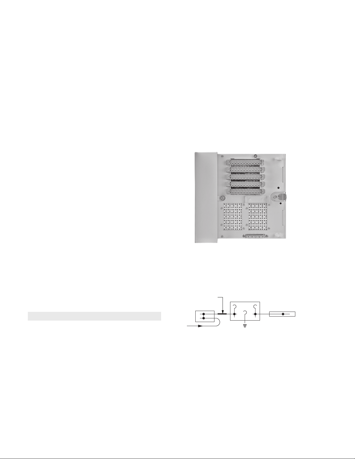
2.2 Open the splicing chamber by loosening the bolt securing the splicing chamber door. Open the splicing chamber
door. (See-fig. 7.02)
2.3 Pull the preterminated short stub, insulated ground wire, and accessories out of the splicing chamber.
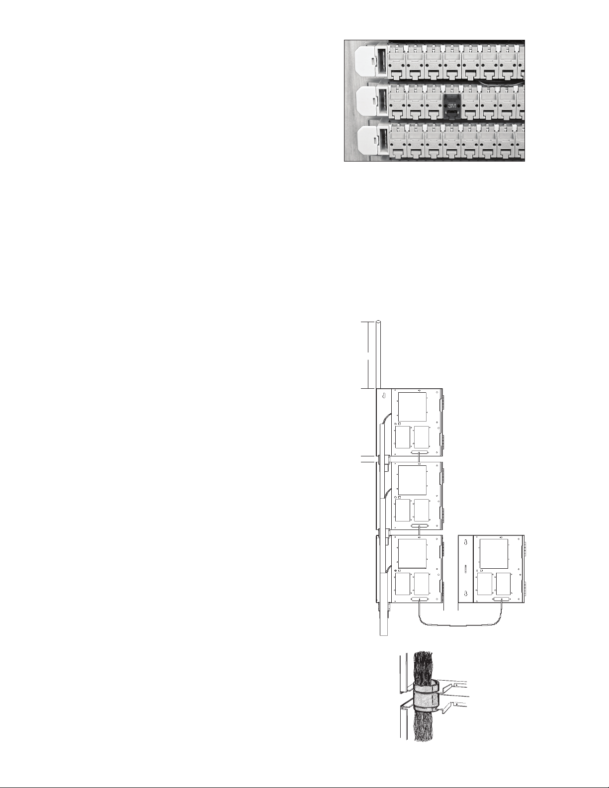
2.4 Mount the terminal in designated position with the three mounting screws provided.
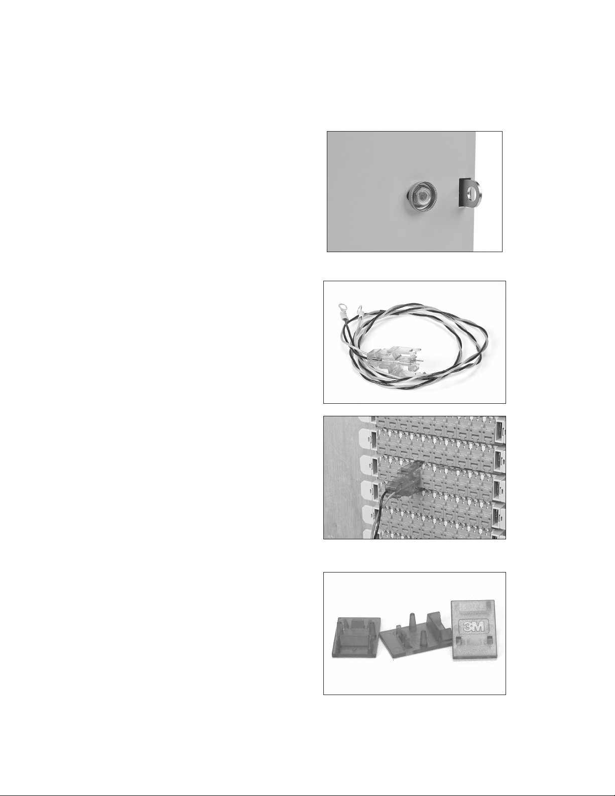
2.5 Remove the jumper wire retaining ring from poly bag and install in faceplate.
3.0 Feeder Cable Preparation and Strain Relief
3.1 Feeder cable diameters for the 3M™ Indoor Building Entrance Terminal (IBET) 4588V-QCS Series
PET Pair Count
Feeder Cable
Minimum Maximum
Diameter Diameter
25 .42" 1.08"
50 .63" 1.45"
If the cable diameter is smaller than the minimum, use 3M™ 130C tape to build up to the minimum.
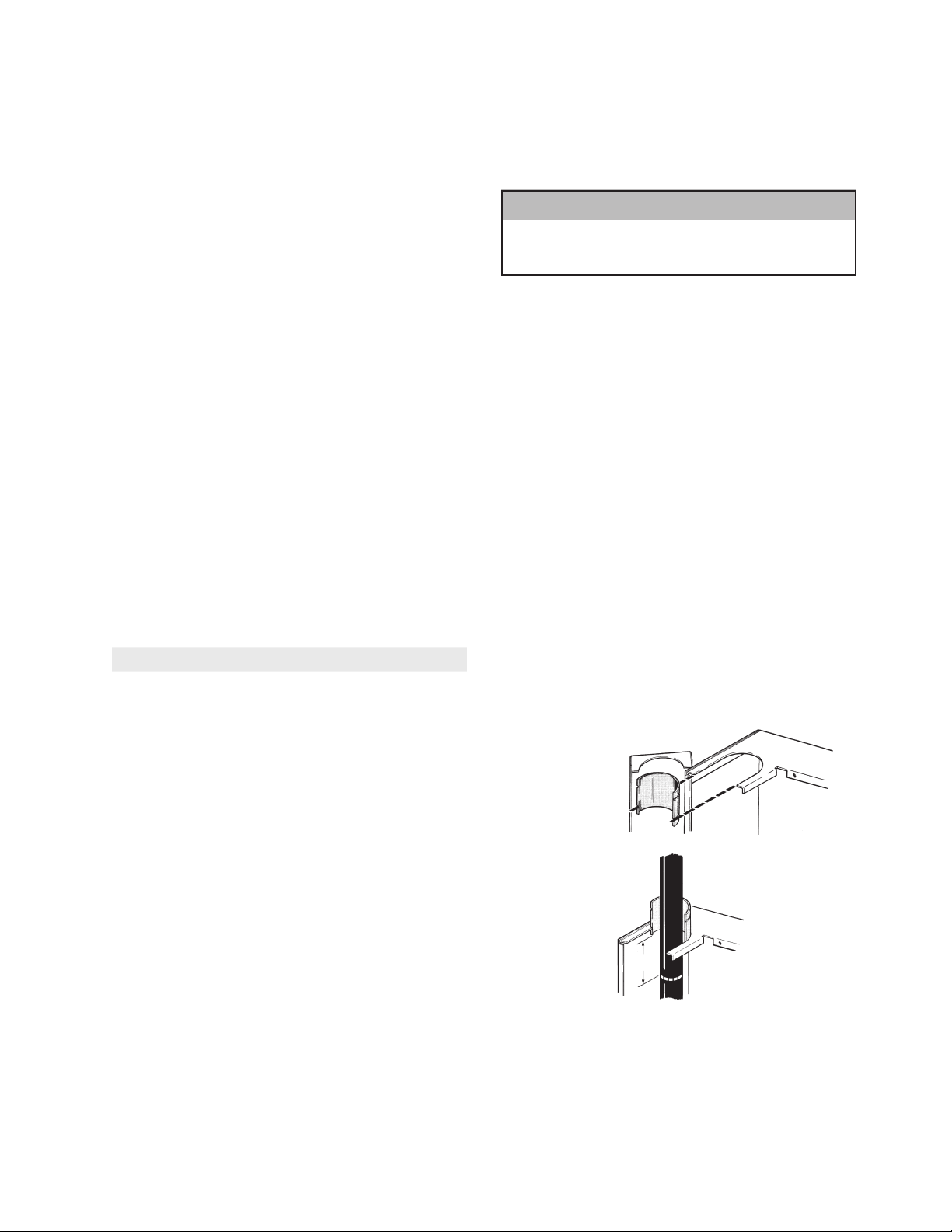
3.2 Run the feeder cable 24" past the IBET terminal
cable entry port.
3.3 Slide the 3M™ Pull ’N’ Shrink Tube (PST) on the
end of the cable with the pull-tab away from the
IBET terminal and temporarily keep it out of the
way.
3.4 With the groove toward the IBET terminal and
long end toward the cable, snap the cable gland
halves around the cable. Slide the gland into the
entry port of the IBET terminal.
3.5 Measure 2" of sheath past the gland inside the
IBET terminal. Pull the gland and cable out of the
IBET terminal.
843014
2"
25-50
pair
100 pair

4 78-0013-1813-4-A
3.6 Remove the sheath, leaving at least 21" of free
conductor length. Identify and secure the cable
groups ends. Bond the cable shield according to
your company’s practice.
3.7 Insert the gland’s groove into the cable port. Slide
the 3M™ Pull ’N’ Shrink Tube (PST) over the
gland and slowly unwind the core. The PST fits
over either the small diameter of the 25-50 pair
gland or butts up against the 3M™ Indoor Building
Entrance Terminal (IBET) 4588V-QCS for the 100
pair gland.
822357
25-50
pair
843016
3.8 Complete the PST core removal over the gland.
3.9 The blank plate MUST be used in the empty cable
port for UL Listing.
3.10 Attach the cable to the wall according to your
company’s practice.
4.0 Terminal Grounding
4.1 Fasten a #6 AWG wire to the ground bar which is located on the front of the unit. Connect other end of ground
wire to local ground per company standards.
Note: Failure to properly bond and ground the terminal per N.E.C. or local equivalent codes may render
protection arrestors useless.
4.2 Module splicing. Splice per your company practice.
4.3 Splice the feeder cable groups to the corresponding connectorized stubs according to your company’s practice.
4.4 3M™ Scotchlok™ Connector or individual connector splicing
4.5 Splice the feeder cable groups to the corresponding connectorized stubs in the IBET terminal according to your
company’s practice.
4.6 When all splicing is completed, bundle the groups and secure them with tie wraps into the splice chamber on the
left side.
4.7 Close the IBET terminal splice chamber cover and secure with the lockplate bolt. (See 7.02)
5.0 Distribution (House) Wire Termination
5.1 Remove the block from frame. Rotate the block
180°. backward and remount in same frame
position with 1-pair jumper caps facing out.
Push the block firmly into place on the frame.
Cable pairs should now enter the back side of
the block from below. Repeat until all feeder and
distribution blocks have been terminated and
mounted to frame.

78-0013-1813-4-A 5
6.0 Running Jumpers 3M™ Quick Connect System 2810 Block
6.1 Open the feeder pair jumper cap by pushing up on
the latch and rotating up. Insert jumper wire ends
A (tip) left and B (ring) right into wire openings in
the cap, making sure they are inserted all the way
to the back of the cap.
6.2 While holding the jumper wires in place, close the
cap and press to snap the latch firmly into place.
6.3 Route the jumper wires to the distribution pair
through wire loops on the block ends and through
vertical and horizontal wireways. Cut jumper
wires to appropriate length, leaving at least 5 cm
(2 in.) of slack.
6.4 Terminate the jumper wires to the distribution pair
by repeating the procedure described in steps 3.1
and 3.2.
6.5 Terminate additional jumper wires by repeating
the above procedure.
6.6 To remove jumper wires, open the cap and pull the
wires straight out from block.
6.7 Route the wire below the connected cap.
7.0 Installing the Electrical Protectors
Note: Use ONLY UL Recognized or Listed
protectors in the IBET.
7.1 The 3M™ Indoor Building Entrance Terminal
(IBET) 4588V-QCS uses a standard five pin
protector receptacle field. The long pins of the
protector connect Tip and Ring from the feeder
cable though the protector to the short pins to the
distribution/house wire.
7.2 Insert protectors into the protector receptacle field
according to your company’s practice.

6 78-0013-1813-4-A
7.3 To disconnect the distribution wire, pull the
protector out to the detents on the long pins to
hold it in place. This continues to protect from the
feeder cable side.
8.0 Protective Cover
8.1 With the cover closed, the exposed hasp allows for
locking when security is required.
9.0 3M™ Single Pair Test Probe 2827
9.1 Testing using 3M™ Single Pair Test Probe 2827
9.2 Plug the test probe into the cap of the pair being
tested, with the black lead to the left and the red
lead to the right.
10.0 3M™ Priority Caps
10.1 Priority Caps are used to designate special purpose
circuits and prevent entry of the 3M Single Pair Test
Probe.

78-0013-1813-4-A 7
10.2 To install Priority Caps, place over the jumper cap
of the pair to be marked and push it into place.
Latching is indicated by an audible snap.
11.0 Multiple 3M™ Indoor Building Entrance Terminal (IBET) 4588V-QCS
Installation
Note: Use this application when the required
cable pair capacity exceeds the capacity of
a single IBET Terminal.
11.1 The design of the splice chamber and the grooved
cable glands make it possible to stack the IBET
terminal vertically, up to three of the same cable
pair count and within the diameter limits in the
chart in 3.01.
11.2 Mounting the IBET terminal
a) Mount the IBET terminal bodies using the
cable glands to position them.
b) Assemble the feeder cable strain relief
according to Section 3.0 and prepare the
feeder cable so that 21" of free conductor
length will be in the last IBET terminal.
1"
minimum
21"
2.75"
minimum
11.3 Place cable glands around the free conductors and
position into the IBET terminal.
11.4 Separate the feeder cable pair assigned to each
IBET terminal; splice and bond the IBET terminal
according to section 4.0.
843017

8 78-0013-1813-4-A

78-0013-1813-4-A 9

3M, MS2 and Scotchlok are trademarks of 3M Company.
Important Notice
All statements, technical information, and recommendations related to 3M’s products are based on information believed to be reliable,
but the accuracy or completeness is not guaranteed. Before using this product, you must evaluate it and determine if it is suitable for
your intended application. You assume all risks and liability associated with such use. Any statements related to the product which are
not contained in 3M’s current publications, or any contrary statements contained on your purchase order shall have no force or effect
unless expressly agreed upon, in writing, by an authorized officer of 3M.
Warranty; Limited Remedy; Limited Liability.
This product will be free from defects in material and manufacture for a period of one (1) year from the time of purchase. 3M MAKES
NO OTHER WARRANTIES INCLUDING, BUT NOT LIMITED TO, ANY IMPLIED WARRANTY OF MERCHANTABILITY OR FITNESS FOR
A PARTICULAR PURPOSE. If this product is defective within the warranty period stated above, your exclusive remedy shall be, at
3M’s option, to replace or repair the 3M product or refund the purchase price of the 3M product. Except where prohibited by law,
3M will not be liable for any indirect, special, incidental or consequential loss or damage arising from this 3M product,
regardless of the legal theory asserted.
3
Communication Markets Division
6801 River Place Blvd.
Austin, TX 78726-9000
1-800-426-8688
www.3MTelecommunications.com
Please Recycle. Printed in USA.
© 3M 2010. All Rights Reserved.
78-0013-1813-4-A
This manual suits for next models
3
Table of contents
Other 3M Touch Terminal manuals
Popular Touch Terminal manuals by other brands

Touch Dynamic
Touch Dynamic Quest Tablet user manual

DIEBOLD NIXDORF
DIEBOLD NIXDORF BEETLE /XS Operator's manual

Castles Technology
Castles Technology SATURN1000 S1F2 MOB user manual

Rockwell Automation
Rockwell Automation Allen-Bradley PanelView Plus 7 Product information

Avalue Technology
Avalue Technology MTP-1702 Quick reference guide

Panasonic
Panasonic FZ-VEBR11 Series operating instructions