ENERCON E-82 E4 Parts list manual

Technical Description
ENERCON Wind energy converter
E-82 E4

Publisher ENERCON GmbH ▪ Dreekamp 5 ▪ 26605 Aurich ▪ Germany
Phone: +49 4941 927-0 ▪ Fax: +49 4941 927-109
E-mail: [email protected] ▪ Internet: http://www.enercon.de
Managing Directors: Hans-Dieter Kettwig, Nicole Fritsch-Nehring
Local court: Aurich ▪ Company registration number: HRB 411
VAT ID no.: DE 181 977 360
Copyright notice The entire content of this document is protected by the German Copyright Act
(UrhG) and international agreements.
All copyrights concerning the content of this document are held by ENERCON
GmbH, unless another copyright holder is expressly indicated or identified.
Any content made available does not grant the user any industrial property rights,
rights of use or any other rights. The user is not allowed to register any intellectual
property rights or rights for parts thereof.
Any transmission, surrender and distribution of the contents of this document to
third parties, any reproduction or copying, and any application and use - also in part
- require the express and written permission of the copyright holder, unless any of
the above are permitted by mandatory legal regulations.
Any infringement of the copyright is contrary to law, may be prosecuted according
to §§ 106 et seq. of the German Copyright Act (UrhG), and grants the copyright
holder the right to file for injunctive relief and to claim for punitive damages.
Registered trademarks Any trademarks mentioned in this document are intellectual property of the respec-
tive registered trademark holders; the stipulations of the applicable trademark law
are valid without restriction.
Reservation of right
of modification
ENERCON GmbH reserves the right to change, improve and expand this document
and the subject matter described herein at any time without prior notice, unless con-
tractual agreements or legal requirements provide otherwise.
Document information
Document ID D0376616-2
Notation Original document. Source document of this translation: D0363578-2.
Date Language DCC Plant / department
2015-05-08 en DA WRD GmbH / Documentation Department
Legal notice
D0376616-2 / DA ii

Table of contents
1Overview of ENERCON E-82 E4 .......................................................................... 1
2ENERCON wind energy converter concept .......................................................... 2
3E-82 E4 components ............................................................................................ 3
3.1 Rotor blades .......................................................................................................... 4
3.2 Nacelle .................................................................................................................. 4
3.2.1 Annular generator ................................................................................. 4
3.3 Tower .................................................................................................................... 5
4Grid Management System .................................................................................... 6
5Safety system ....................................................................................................... 9
5.1 Safety equipment ................................................................................................. 9
5.2 Sensor system ...................................................................................................... 9
6Control system ...................................................................................................... 12
6.1 Yaw system ........................................................................................................... 12
6.2 Pitch control .......................................................................................................... 12
6.3 WEC start .............................................................................................................. 13
6.3.1 Start lead-up ......................................................................................... 13
6.3.2 Wind measurement and nacelle alignment .......................................... 14
6.3.3 Generator excitation .............................................................................. 14
6.3.4 Power feed ............................................................................................ 14
6.4 Operating modes .................................................................................................. 15
6.4.1 Full load operation ................................................................................ 15
6.4.2 Partial load operation ............................................................................ 16
6.4.3 Idle mode .............................................................................................. 16
6.5 Safe stopping of the wind energy converter .......................................................... 17
7Remote monitoring ................................................................................................ 18
8Maintenance ......................................................................................................... 19
Technical specifications E-82 E4 .......................................................................... 20
Table of contents
D0376616-2 / DA iii

Table of contents
D0376616-2 / DA iv

1Overview of ENERCON E-82 E4
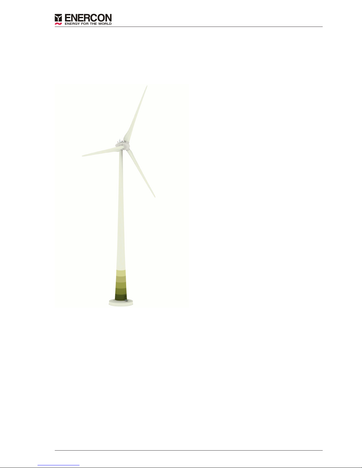
The ENERCON E-82 E4 wind energy converter is a direct-drive wind energy converter with a
three-bladed rotor, active pitch control, variable speed operation, and a nominal power output of
2350/3000 kW. It has a rotor diameter of 82 m and can be supplied with hub heights of 59 m to
84 m.
Fig. 1: Complete view of ENERCON E-82 E4
Overview of ENERCON E-82 E4
D0376616-2 / DA 1 of 21

2ENERCON wind energy converter concept
ENERCON wind energy converters are characterised by the following features:
Gearless
The E-82 E4 drive system comprises very few rotating components. The rotor hub and the rotor of
the annular generator are directly interconnected to form one solid unit. This reduces the mechani‐
cal strain and increases technical service life. Maintenance and service costs are reduced (fewer
wearing parts, no gear oil change, etc.) and operating expenses also decrease. Since there are no
gears or other fast rotating parts, the energy loss between generator and rotor as well as noise
emissions are considerably reduced.
Active pitch control
Each of the three rotor blades is equipped with a pitch unit. Each pitch unit consists of an electrical
drive, a control system, and a dedicated emergency power supply. The pitch units limit the rotor
speed and the amount of power extracted from the wind. In this way, the maximum output of the
E-82 E4 can be accurately limited to nominal power, even at short notice. By pitching the rotor
blades into the feathered position, the rotor is stopped without any strain on the drive train caused
by the application of a mechanical brake.
Indirect grid connection
The power produced by the annular generator is fed into the distribution or transport grid via the
ENERCON Grid Management System. The ENERCON Grid Management System, which consists
of a rectifier, a DC link and a modular inverter system, ensures maximum energy yield with excel‐
lent power quality. The electrical properties of the annular generator are therefore irrelevant to the
behaviour of the wind energy converter in the distribution or transport grid. Rotational speed, exci‐
tation, output voltage and output frequency of the annular generator may vary depending on the
wind speed. In this way, the energy contained in the wind can be optimally exploited even in the
partial load range.
ENERCON wind energy converter concept
D0376616-2 / DA 2 of 21

3E-82 E4 components
Fig. 2: View of nacelle
1Slip ring unit 8 Generator filter cabinet
2 Hub 9 Excitation controller box
3 Blade adapter 10 Nacelle converter cabinet
4 Generator stator 11 Yaw drives
5 Generator rotor 12 Main carrier
6 Stator shield 13 Blade extension
7 Rectifier cabinet 14 Rotor blade
E-82 E4 components
D0376616-2 / DA 3 of 21

3.1 Rotor blades
The rotor blades made of glass-fibre reinforced plastic (glass fibre + epoxy resin) have a major in‐
fluence on the wind energy converter’s yield and its noise emission. The shape and profile of the
E-82 E4 rotor blades were designed with the following criteria in mind:
■High power coefficient
■Long service life
■Low noise emissions
■Low mechanical strain
■Efficient use of material
One special feature to be pointed out is the new rotor blade profile, which extends down to the na‐
celle. This design eliminates the loss of the inner air flow experienced with conventional rotor
blades. In combination with the streamlined nacelle, utilisation of the wind supply is considerably
optimised.
The rotor blades of the E-82 E4 were specially designed to operate with variable pitch control and
at variable speeds. The PU-based surface coating protects the rotor blades from environmental im‐
pacts such as UV radiation and erosion. This coating is highly resistant to abrasion and visco-hard.
Microprocessor-controlled pitch units that are independent of one another adjust each of the three
rotor blades. An angle encoder in each rotor blade constantly monitors the set blade angle and en‐
sures blade angle synchronisation across all three blades. This provides for quick, accurate adjust‐
ment of blade angles according to the prevailing wind conditions.
3.2 Nacelle
3.2.1 Annular generator
ENERCON wind energy converters (WECs) are equipped with a multi-polar, separately excited
synchronous generator (annular generator). The WEC operates at variable speeds so as to opti‐
mally utilise the wind energy potential. The annular generator therefore produces alternating cur‐
rent with varying voltage, frequency and amplitude.
The windings in the stator of the annular generator form two three-phase alternating current sys‐
tems that are independent of each other. Both systems are rectified independently of each other in
the nacelle and combined by the direct-current distribution system. In the tower base the inverters
reconvert the current into three-phase current whose voltage, frequency, and phase position con‐
form to the grid.
Consequently, the annular generator is not directly connected to the receiving power grid of the
utility/power supply company; instead, it is completely decoupled from the grid by the full-scale
converter.
E-82 E4 components
D0376616-2 / DA 4 of 21

3.3 Tower
The tower of the E-82 E4 wind energy converter is either a steel tower or a concrete tower made of
precast segments. Towers with different heights are available.
All towers are painted and equipped with weather and corrosion protection at the factory. This
means that no work is required in this regard after assembly except for repairing any defects or
transport damage. By default, the bottom of the tower comes with graduated paintwork (can be dis‐
pensed with if desired).
Steel towers are steel tubes that taper linearly towards the top. They are prefabricated and consist
of a small number of large sections. Flanges with drill holes for bolting are welded to the ends of
the sections.
The tower sections are simply stacked on top of each other and bolted together at the installation
site. They are linked to the foundation by means of a bolt cage.
The concrete tower is assembled from the precast concrete elements at the installation site. As a
rule, segments are dry-stacked; however, a compensatory grout layer can be applied. Vertical
joints are closed by means of bolt connections.
Towers are prestressed vertically by means of prestressing steel tendons. The prestressing ten‐
dons run externally along the interior tower wall. They are anchored to the foundation.
For technical and financial reasons, the top slender part of the E-82 E4 concrete tower is made of
steel. For instance, installing the yaw bearing directly on the concrete elements is unfeasible, and
the considerably thinner wall of the steel section provides for more space in the tower interior.
E-82 E4 components
D0376616-2 / DA 5 of 21

4Grid Management System
The annular generator is coupled to the grid through the ENERCON Grid Management System.
The main components of this system are a rectifier, a DC link, and several modular inverters.
Annular
generator Rectifier DC link Inverter Filters Transformer Power circuit
breaker Grid
ENERCON control system
Excitation controller
Fig. 3: Simplified electric diagram of an ENERCON WEC
The Grid Management System, generator excitation and pitch control are all managed by the con‐
trol system to achieve maximum energy yield and excellent power quality.
Decoupling the annular generator from the grid guarantees ideal power transmission conditions.
Sudden changes in wind speed are translated into controlled change in order to maintain stable
grid feed. Conversely, possible grid faults have virtually no effect on WEC mechanics. The power
injected by the E-82 E4 can be precisely regulated from 0 kW to 2350/3000 kW.
In general, the features required for a certain wind energy converter or wind farm to be connected
to the receiving power grid are predefined by the operator of that grid. To meet different require‐
ments, ENERCON wind energy converters are available with different configurations.
The inverter system in the tower base is dimensioned according to the particular WEC configura‐
tion. As a rule, a transformer inside or near the wind energy converter converts 400 V low voltage
to the desired medium voltage.
Grid Management System
D0376616-2 / DA 6 of 21

Reactive power
If necessary, an E-82 E4 equipped with standard FACTS (Flexible AC Transmission System) con‐
trol can supply reactive power in order to contribute to reactive power balance and to maintaining
voltage levels in the grid. The maximum reactive power range is available at an output as low as
10 % of the nominal active power. The maximum reactive power range varies, depending on the
WEC configuration.
FT configuration
By default, the E-82 E4 comes equipped with FACTS technology that meets the stringent require‐
ments of specific grid codes. It is able to ride through grid faults (undervoltage, overvoltage, auto‐
matic reclosing, etc.) of up to 5 seconds (FT = FACTS + FRT [Fault Ride Through]) and to remain
connected to the grid during these faults.
If the voltage measured at the reference point exceeds a defined limit value, the ENERCON wind
energy converter changes from normal operation to a specific fault operating mode.
Once the fault has been cleared, the wind energy converter returns to normal operation and feeds
the available power into the grid. If the voltage does not return to the operating range admissible
for normal operation within an adjustable time frame (5 seconds max.), the wind energy converter
is disconnected from the grid.
While the system is riding through a grid fault, various fault modes using different grid feed strat‐
egies are available, including feeding in additional reactive current in the event of a fault. The con‐
trol strategies include different options for setting fault types.
Selection of a suitable control strategy depends on specific grid code and project requirements that
must be confirmed by the particular grid operator.
FTQ configuration
The FTQ configuration (FT plus Q+ option) comprises all features of the FT configuration. In addi‐
tion, it has an extended reactive power range.
FTQS configuration
The FTQS configuration comprises all features of the FTQ configuration and has been expanded
to include the STATCOM (Static Synchronous Compensator) option. The STATCOM option ena‐
bles the wind energy converter to output and absorb reactive power regardless of whether it gener‐
ates and feeds active power into the grid. It is thus able to actively support the power grid at any
time, similar to a power plant.
Grid Management System
D0376616-2 / DA 7 of 21

Frequency protection
ENERCON wind energy converters can be used in grids with a nominal frequency of 50 Hz or
60 Hz.
The range of operation of the E-82 E4 is defined by a lower and upper frequency limit value. Over‐
frequency and underfrequency events at the WEC reference point trigger frequency protection and
cause the WEC to shut down after the maximum delay time of 60 seconds has elapsed.
Power-frequency control
If temporary overfrequency occurs as a result of a grid fault, ENERCON wind energy converters
can reduce their power feed dynamically to contribute to restoring the balance between the gener‐
ating and transmission networks.
As a pre-emptive measure, the active power feed of ENERCON wind energy converters can be
limited during normal operation. During an underfrequency event, the power reserved by this limita‐
tion is made available to stabilise the frequency. The characteristics of this control system can be
easily adapted to different specifications.
Grid Management System
D0376616-2 / DA 8 of 21

5Safety system
The E-82 E4 comes with a large number of safety features whose purpose is to permanently keep
the WEC inside a safe operating range. In addition to components that ensure safe stopping of the
wind energy converter, these include a complex sensor system. It continuously captures all rele‐
vant operating states of the wind energy converter and makes the relevant information available
through the ENERCON SCADA remote monitoring system.
If any safety-relevant operating parameters are out of the permitted range, the WEC will continue
running at limited power or it will stop.
5.1 Safety equipment
Emergency stop button
In an ENERCON wind energy converter there are emergency stop buttons next to the tower door,
on the control cabinet in the tower base, on the nacelle control cabinet and, if required, on further
levels of the E-module. Actuating an emergency stop button activates the rotor brake. Emergency
pitching of the rotor blades takes place.
The following are still supplied with power:
■Rotor brake
■Beacon system components
■Lighting
■Sockets
Main switch
In an ENERCON wind energy converter, main switches are installed on the control cabinet and the
nacelle control cabinet. When actuated, they de-energise virtually the entire wind energy converter.
The following are still supplied with power:
■Beacon system components
■Service hoist
■Sockets
■Lighting
■Medium-voltage area
5.2 Sensor system
There is a large number of sensors that continuously monitor the current status of the wind energy
converter and the relevant ambient parameters (e.g. rotor speed, temperature, blade load, etc.).
The control system analyses the signals and regulates the wind energy converter such that the
wind energy available at any given time is always optimally exploited and operating safety is ensur‐
ed at the same time.
Redundant sensors
In order to be able to check plausibility by comparing the reported values, more sensors than nec‐
essary are installed for some operating states (e.g. for measuring the generator temperature). De‐
fective sensors are reliably detected and can be replaced by activation of a spare sensor. In this
way, the wind energy converter can safely continue its operation without the need for replacement
of major components.
Safety system
D0376616-2 / DA 9 of 21

Sensor checks
Proper functioning of all sensors is either regularly checked by the WEC control system itself dur‐
ing normal WEC operation or, where this is not possible, in the course of WEC maintenance work.
Speed monitoring
The control system of the ENERCON wind energy converter regulates the rotor speed by adjusting
the blade angle in such a way that the speed does not significantly exceed rated speed even dur‐
ing very high winds. However, this pitch control system may not be able to react quickly enough to
sudden events such as strong gusts of wind or a sudden drop of the generator load. If rated speed
is exceeded by more than 15 %, the control system stops the rotor. After three minutes, the wind
energy converter automatically attempts to restart. If this fault occurs more than five times within 24
hours, the control system assumes a defect and does not attempt any further restarts.
In addition to the electronic monitoring system, each of the three pitch control boxes is fitted with
an electromechanical overspeed switch. Each of these switches can stop the wind energy convert‐
er via emergency pitching. The switches respond if the rotor speed exceeds the rated speed by
more than 25 %. To enable the wind energy converter to restart, the overspeed switches must be
reset manually after the cause of the overspeed has been identified and eliminated.
Vibration monitoring
The vibration sensor serves to detect excessive vibrations and shocks such as might be caused by
a malfunction in the rectifier. It is mounted on the bottom of the main carrier of the wind energy
converter and consists of a limit switch with a spring rod that has a ball attached to one end by a
chain. The ball sits on top of a short vertical pipe. In the event of strong vibrations, the ball falls
from its seat on the pipe, activates the switch by pulling the chain and thereby initiates emergency
pitching of the rotor blades that stops the rotor.
Air gap monitoring
Microswitches distributed along the rotor circumference monitor the width of the air gap between
the rotor and the stator of the annular generator. If any of the switches is triggered because the
distance has dropped below the minimum distance, the wind energy converter stops and restarts
automatically after a brief delay.
If the fault recurs within 24 hours, the wind energy converter remains stopped until the cause has
been eliminated.
Safety system
D0376616-2 / DA 10 of 21

Oscillation monitoring
Oscillation monitoring detects excessive oscillation or excursion of the wind energy converter tower
top.
Two acceleration sensors detect the acceleration of the nacelle along the direction of the hub axis
(longitudinal oscillation) and perpendicular to this axis (transverse oscillation). The WEC control
system uses this input to calculate the tower excursion compared to its resting position. If the ex‐
cursion exceeds the permissible limit, the wind energy converter stops. It restarts automatically af‐
ter a short delay. The acceleration sensors are mounted on the same support as the vibration sen‐
sor. If multiple out-of-range tower oscillations are recorded within a 24-hour period, the wind ener‐
gy converter does not attempt any further restarts.
Temperature monitoring
The components of the ENERCON wind energy converter are cooled by an air cooling system. In
addition, temperature sensors continuously measure the temperature of WEC components that
need to be protected from excessive heat.
In the event of excessive temperatures, the power output of the wind energy converter is reduced.
If necessary, the WEC stops. The wind energy converter cools down and typically restarts auto‐
matically as soon as the temperature falls below a predefined limit.
Some measuring points are equipped with additional overtemperature switches. These also initiate
a stop of the wind energy converter, but without an automatic restart after cooling down, once the
temperature exceeds a specific limit.
At low temperatures, some assemblies such as the pitch system emergency power supply and the
generator are heated in order to keep them operational.
Noise monitoring sensors
Sensors located in the rotor head respond to loud knocking sounds such as might be caused by
loose or defective components. If any of these sensors detects any noise and there is nothing to
indicate a different cause, the wind energy converter stops.
In order to rule out exterior causes for the noise (mainly the impact of hail during a thunderstorm),
the signals from all wind energy converters in a wind farm are matched against each other. If the
sensors in multiple WECs are detecting noise at the same time, an exterior cause is assumed. The
noise sensors are deactivated briefly so that none of the wind energy converters in the wind farm
stops. For wind energy converters outside of wind farms, the signal from a noise sensor in the ma‐
chine house is used for reference.
Cable untwisting
If the nacelle of the wind energy converter has turned around its own axis up to three times and
twisted the cables running down inside the tower, the WEC control system uses the next opportuni‐
ty to automatically untwist the cables.
The cable untwisting system includes a sensor system with an angle encoder with two programma‐
ble relays that travel along in the yaw bearing gear rim. If outside the permitted range, the power
supply to the yaw motors is cut.
Safety system
D0376616-2 / DA 11 of 21

6Control system
The E-82 E4 control system is based on a microprocessor system developed by ENERCON and
uses sensors to query all WEC components and collect data such as wind direction and wind
speed. Using this information, it adjusts the operating mode of the E-82 E4 accordingly. The WEC
display of the control cabinet in the tower base shows the current status of the wind energy con‐
verter and any fault that may have occurred.
6.1 Yaw system
The yaw bearing with an externally geared rim is mounted on top of the tower. The yaw bearing
allows the nacelle to rotate, thus providing for yaw control.
If the difference between the wind direction and the rotor axis direction exceeds the maximum per‐
missible value, the yaw drives are activated and adjust the nacelle position according to the wind
direction. The yaw motor control system ensures smooth starting and stopping of the yawing mo‐
tion. The WEC control system monitors the yaw system. If it detects any irregularities it deactivates
yaw control and stops the wind energy converter.
6.2 Pitch control
Functional principle
The pitch control system modifies the angle of attack, i.e., the angle at which the air flow meets the
blade profile. Changes to the blade angle change the lift at the rotor blade and thus the force with
which the rotor blade turns the rotor.
During normal operation (automatic mode) the blade angle is adjusted in a way that ensures opti‐
mal exploitation of the energy contained in the wind while avoiding overload of the wind energy
converter. Wherever possible, boundary conditions such as noise optimisation are also fulfilled in
the process. In addition, blade angle adjustment is used to decelerate the rotor aerodynamically.
If the wind energy converter achieves nominal power output and the wind speed continues to in‐
crease, the pitch system turns the rotor blades just far enough out of the wind to keep the rotor
speed and the amount of energy extracted from the wind, i.e., the energy to be converted by the
generator, within or just slightly above the rated limits.
Assembly
Each rotor blade is fitted with a pitch unit. The pitch unit consists of a pitch control box, a blade
relay box, a pitch motor and a capacitor unit. The pitch control box and the blade relay box control
the pitch motor. The capacitor box stores the energy required for emergency pitching; during WEC
operation, it is kept charged and tested continually.
Control system
D0376616-2 / DA 12 of 21

Blade angles
Special rotor blade positions (blade angles) of the E-82 E4 :
A: 2.5° Regular position during partial load operation: Maximum exploitation of available
wind energy.
B: 60° Idle mode (wind energy converter does not feed any power into the grid because the
wind speed is too low): Depending on the wind speed, the rotor spins at low speed or
stands still (if there is no wind at all).
C: 92° Feathered position (rotor has been stopped manually or automatically): The rotor
blades do not generate any lift even in the presence of wind; the rotor stands still or
moves very slowly.
Fig. 4: Special blade positions
6.3 WEC start
6.3.1 Start lead-up
As long as the main status is > 0, the wind energy converter remains stopped. As soon as the main
status changes to 0, the WEC is ready and the start-up procedure is initiated. If certain boundary
conditions for start-up, e.g. charging of the emergency pitching capacitors, have not been fulfilled
yet, status 0:3 - Start lead-up is displayed.
During the start lead-up, a wind measurement and alignment phase of 150 seconds begins.
Control system
D0376616-2 / DA 13 of 21

6.3.2 Wind measurement and nacelle alignment
After completing the start lead-up, status 0:2 - Turbine operational is displayed.
If the control system is in automatic mode, the average wind speed is above 1.8 m/s and the wind
direction deviation is sufficient for yawing, the WEC starts alignment with the prevailing wind direc‐
tion. 60 seconds after completing the start lead-up the WEC goes into idle mode. The rotor blades
are slowly pitched in as a check is performed on the emergency pitching capacitors.
If the WEC is equipped with load control sensors, the rotor blades stop at an angle of 70° and ad‐
just the load measurement points, which might take several minutes. During this time, status 0:5
- Calibration of load control is displayed.
If the average wind speed during the wind measurement and alignment phase of 150 seconds is
above the current start wind speed (about 2.0 m/s), the start-up procedure is initiated (status 0:1).
Otherwise, the wind energy converter remains in idle mode (status 2:1 - Lack of wind :
Wind speed too low).
Power consumption
As the wind energy converter is not supplying any active power at that moment, the electrical ener‐
gy consumed by the WEC is taken from the grid.
6.3.3 Generator excitation
Once the rotor reaches a certain rotational speed that depends on the WEC type (for instance, ap‐
prox. 3 rpm with the E-82), generator excitation is initiated. The electricity required for this purpose
is temporarily taken from the grid. Once the generator reaches a sufficient speed the WEC sup‐
plies itself with power. The electricity for self-excitation is then taken from the DC link; the energy
taken from the grid is reduced to zero.
6.3.4 Power feed
As soon as the DC link voltage is sufficient and the excitation controller is no longer connected to
the grid, power feed is initiated. After the rotational speed has increased due to sufficient wind and
with a power setpoint Pset > 0, the line contactors on the low-voltage side are closed and the WEC
starts feeding power into the grid.
The number of activated inverters is gradually increased, depending on the number necessary for
the power generated by the generator. Power control regulates the excitation current so that power
is fed according to the required power curve.
The power increase gradient (dP/dt) after a grid fault or a regular start-up can be defined within a
certain range in the control system. For more detailed information, see the
Grid Performance
data
sheet for the particular ENERCON WEC type.
Control system
D0376616-2 / DA 14 of 21

6.4 Operating modes
After completion of the E-82 E4 start-up procedure the wind energy converter switches to automat‐
ic mode (normal operation). While in operation, the WEC constantly monitors wind conditions, opti‐
mises rotor speed, generator excitation and generator power output, aligns the nacelle position
with the wind direction, and captures all sensor statuses.
In order to optimise power generation in highly diverse wind conditions when in automatic mode,
the WEC changes between three operating modes, depending on the wind speed. In certain cir‐
cumstances the WEC stops if provided for by the WEC configuration (e.g. shadow shutdown). In
addition, the utility company into whose grid the generated power is fed can be given the option to
directly intervene in the operation of the wind energy converter by remote control, e.g. in order to
temporarily reduce the power feed.
The E-82 E4 switches between the following operating modes:
■Full load operation
■Partial load operation
■Idle mode
6.4.1 Full load operation
Wind speed
v ≥ 13.9 (2.35 MW) / 16 (3 MW) m/s
With wind speeds at and above the rated wind speed, the wind energy converter uses pitch control
to maintain rotor speed at rated (approx. 17.5 rpm) and thus limits the power to its nominal value of
2350/3000 kW.
Storm Control enabled (normal case)
Storm Control enables WEC operation even at very high wind speeds; however, the rotor speed
and the power output are reduced.
If wind speeds exceed approx. 28 m/s (12-second average) and keep increasing, the rotational
speed will be reduced linearly from 17.5 rpm to idle speed at about 34 m/s by pitching the rotor
blades out of the wind accordingly. The power fed into the grid decreases in accordance with the
speed/power curve in the process.
At wind speeds above 34 m/s (10-minute average) the rotor blades are almost in the feathered po‐
sition. The WEC runs in idle mode and without any power output; it does, however, remain connec‐
ted to the receiving grid. Once the wind speed falls below 34 m/s, the WEC restarts its power feed.
Storm control is activated by default and can only be deactivated by remote control or on site by
ENERCON Service.
Storm control disabled
If, by way of exception, storm control is disabled, the wind energy converter will be stopped for
safety reasons if the wind speed exceeds 25 m/s (3-minute average) or 30 m/s (15-second aver‐
age). If none of the above events occurs within 10 minutes after stopping, the wind energy convert‐
er will be restarted automatically.
Control system
D0376616-2 / DA 15 of 21

6.4.2 Partial load operation
Wind speed
2.5 m/s ≤ v < 13.9 (2.35 MW) / 16 (3 MW) m/s
During partial load operation (i.e., the wind speed is between the cut-in wind speed and the rated
wind speed) the maximum possible power is extracted from the wind. Rotor speed and power out‐
put are determined by the current wind speed. Pitch control already starts as the WEC approaches
full load operation so as to achieve a smooth transition.
6.4.3 Idle mode
Wind speed
v < 2.5 m/s
At wind speeds below 2.5 m/s no power can be fed into the grid. The wind energy converter runs in
idle mode, i.e., the rotor blades are turned almost completely out of the wind (60° blade angle) and
the rotor turns slowly or stops completely if there is no wind at all.
Slow movement (idling) puts less strain on the hub bearings than longer periods of complete stand‐
still; in addition, the WEC can resume power generation and power feed more quickly as soon as
the wind picks up.
Control system
D0376616-2 / DA 16 of 21
Table of contents